
01
أطواق بكرات الطحن
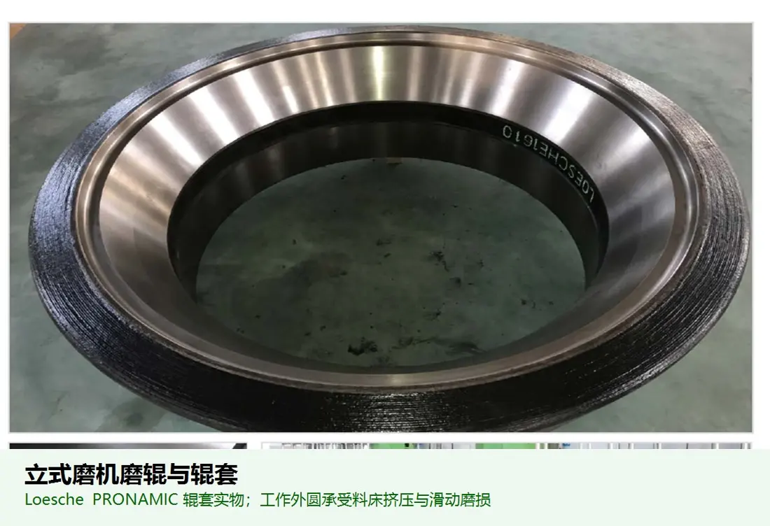
طوق بكرة الطحن
قطع تآكل أساسية في quadropol® تضغط طبقة المادة وتطحنها. طابق المقطع والسطح العامل والتجويف والمفاتيح/المشابك وموضع البكرة وسماحية التآكل مع رسومات التركيب.
عرض صفحة الجزء المشترك →حدد تجهيزات QMR² وQMK² وQMC² وQMS² المركبة، ثم افحص بكرات الطحن والطاولات وحلقات الفوهات والمحامل والأنظمة الهيدروليكية وأنظمة الإدارة لاختيار قطع التآكل وقطع الغيار.
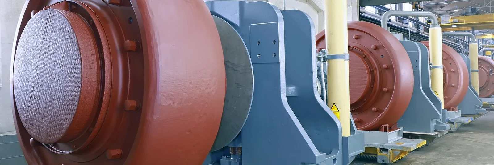
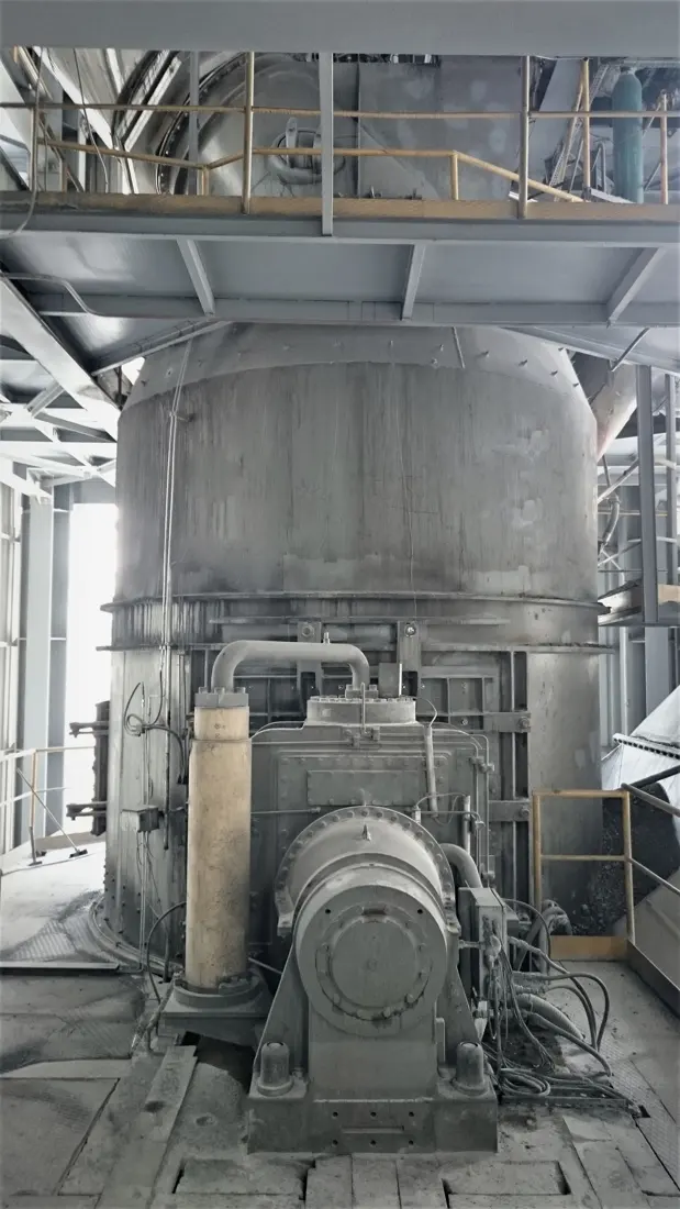
يستخدم quadropol® وحدات بكرات معيارية تجهز بحسب المادة والمشروع. ترد فقط السلاسل والطرازات المركبة التي نشرها المصنع؛ ولا تفسر رموز الطرازات كأبعاد دون دليل. يتطلب التصنيع بيانات لوحة المعدة والرقم التسلسلي ورسومات التركيب ومواضع التوصيل الفعلية.
الطرازات مأخوذة من صفحات منتجات Polysius الحالية ومراجع المشاريع وكتيبات QMR² / QMC² / QMK². لا تستنتج قائمة كاملة للطرازات لم ينشرها المصنع.
| السلسلة / الطراز المنشور | الاستخدام الرئيسي | مرجع منشور لتركيب المعدة | مصدر المعلومات | حالة المنتج |
|---|---|---|---|---|
| QMR² 38/19 | طحن المواد الخام | Oruro، بوليفيا، خط كلنكر 3,000 t/d | مرجع مشروع حالي من المصنع | المنتج الحالي |
| QMR² 43/21 | طحن المواد الخام | تجهيزات منشورة في المكسيك والبرازيل | كتيب المصنع QMR² | منتج الجيل الثاني |
| QMR² 45/23 | طحن المواد الخام | Afyon، تركيا، خط كلنكر 4,000 t/d | مرجع مشروع حالي من المصنع | تجهيز حالي |
| QMR² 48/24 | طحن المواد الخام | Mombasa، كينيا؛ Yamama، السعودية | مرجع مشروع حالي من المصنع | تجهيز حالي |
| QMC² 40/20 | طحن الأسمنت / المواد الأسمنتية | Cementos Cibao، جمهورية الدومينيكان | مرجع مشروع حالي من المصنع | قيد التشغيل منذ 2021 |
| QMC² 45/23 | طحن الأسمنت / المواد الأسمنتية | Oruro، بوليفيا؛ Afyon، تركيا | مرجع مشروع حالي من المصنع | تجهيز حالي |
| QMC² 51/25 | طحن الأسمنت / المواد الأسمنتية | Cemento Progreso، غواتيمالا، 2 وحدة | مرجع مشروع حالي من المصنع | تجهيز حالي |
| QMK² 24/12 | طحن الفحم / فحم الكوك البترولي | Mombasa، كينيا، 3 وحدات بكرات | مرجع مشروع حالي من المصنع | تجهيز حالي |
| QMK² 32/16 | طحن الفحم أو فحم الكوك البترولي أو الليغنيت | الهند وإندونيسيا وتركيا | مرجع مشروع حالي من المصنع | تجهيز حالي |
| QMS² (عائلة منشورة) | طحن الخبث | لا يدرج طراز محدد الأبعاد علنا | حدد من اللوحة ورسومات المشروع | عائلة المنتج الحالية |
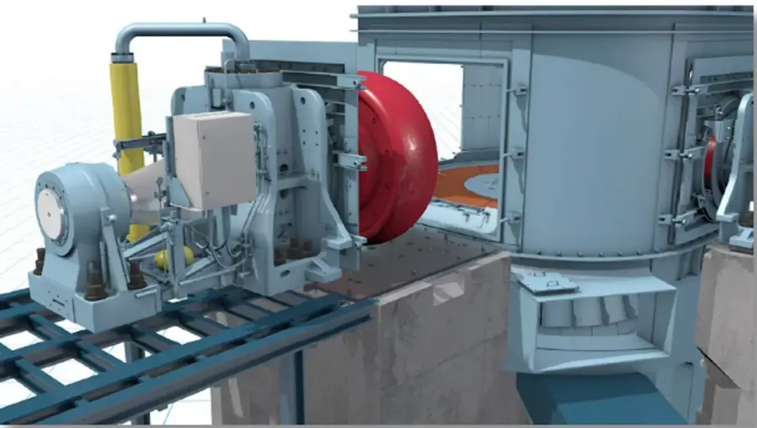
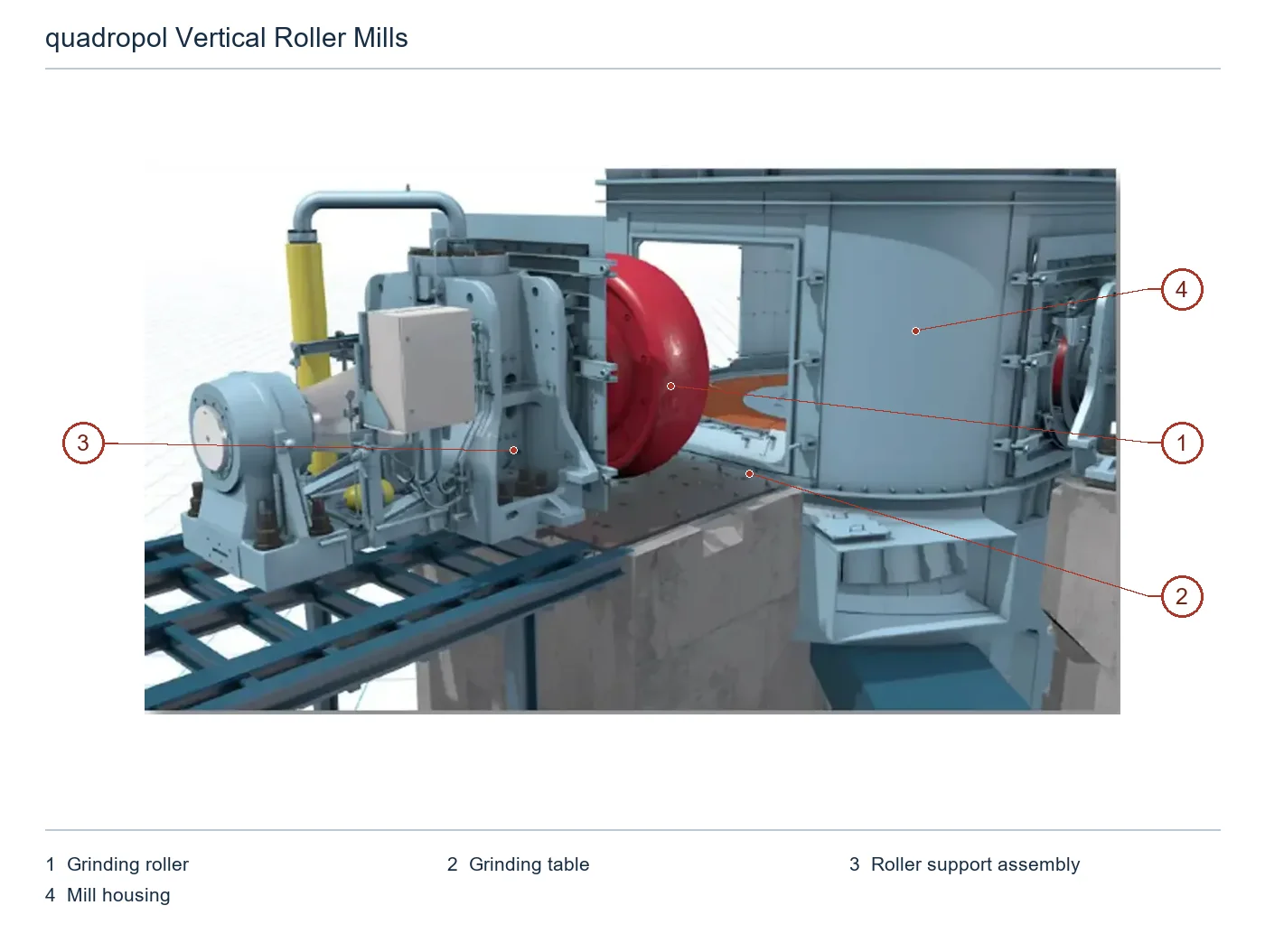
تتطابق الأرقام على المخطط مع الصفوف أدناه.
| الرقم | المكوّن | الموضع | ينطبق على |
|---|---|---|---|
| 1 | بكرة الطحن | بكرة الطحن الحمراء في الوضع المفتوح على اليسار | quadropol |
| 2 | طاولة الطحن | طاولة الطحن البرتقالية الظاهرة داخل المطحنة أسفل البكرة | quadropol |
| 3 | مجموعة دعم البكرة | هيكل دعم البكرة الرمادي إلى يسارها | quadropol |
| 4 | غلاف المطحنة | الغلاف الأسطواني الرمادي حول حجرة الطحن | quadropol |
تختلف الضغوط والصدمات والسحج والتعرية بفعل الهواء والحرارة بحسب الموضع. راجع المادة والطبقة العاملة وطريقة التصنيع كل على حدة.
طوق بكرة الطحن
قطع تآكل أساسية في quadropol® تضغط طبقة المادة وتطحنها. طابق المقطع والسطح العامل والتجويف والمفاتيح/المشابك وموضع البكرة وسماحية التآكل مع رسومات التركيب.
عرض صفحة الجزء المشترك →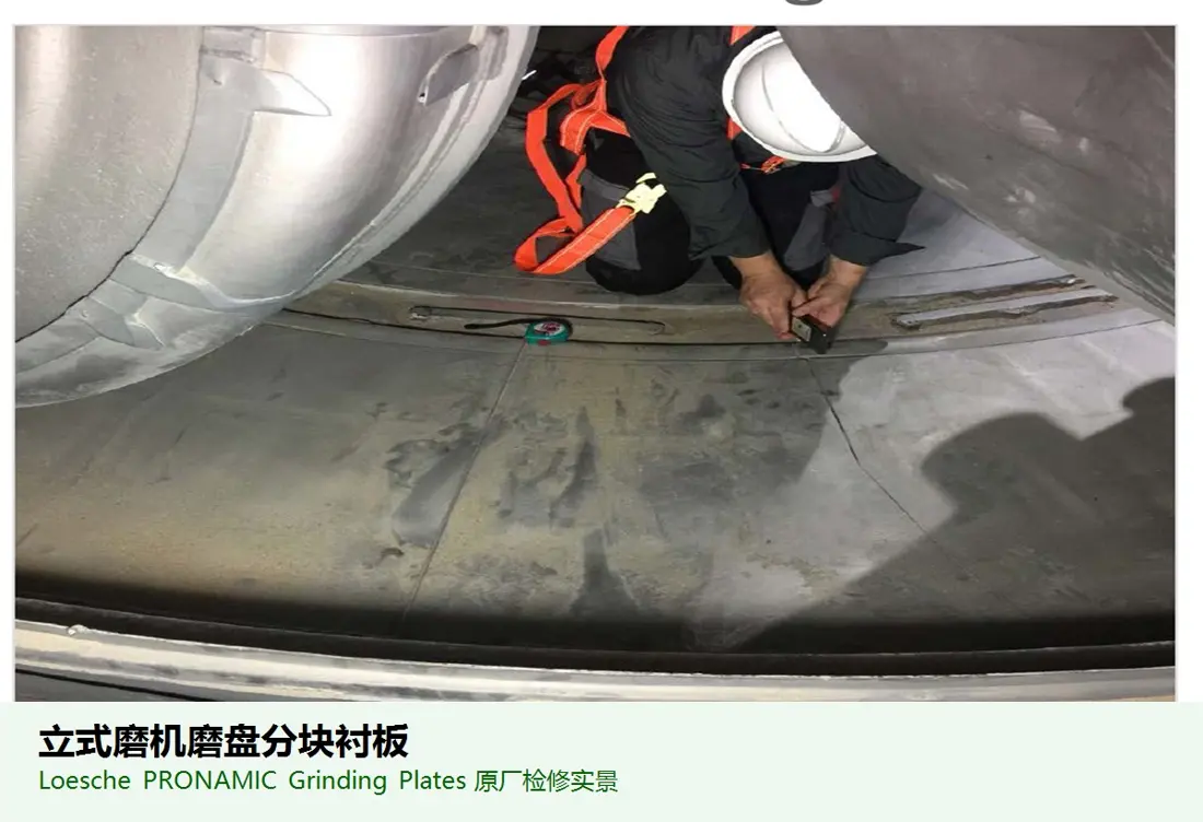
بطانة / قطاع طاولة الطحن
تشكل سطح الطاولة الدوارة وطبقة الطحن مع البكرات. افحص معا عدد القطاعات وانحناءاتها وسماكتها وثقوبها ومواضعها الداخلية/الخارجية ومواضع اتصال حلقة الاحتجاز وقوالب قياس التآكل.
عرض صفحة الجزء المشترك →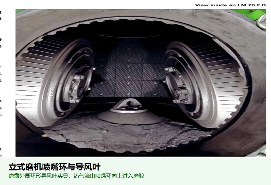
حلقة الفوهات / حلقة الريش
تنظم الهواء الصاعد حول الطاولة لنقل المادة. طابق زوايا الريش ومساحة مرور الهواء والأقسام والأقطار والتثبيت والخلوص عن الطاولة مع الغلاف والتجهيزات التشغيلية.
عرض صفحة الجزء المشترك →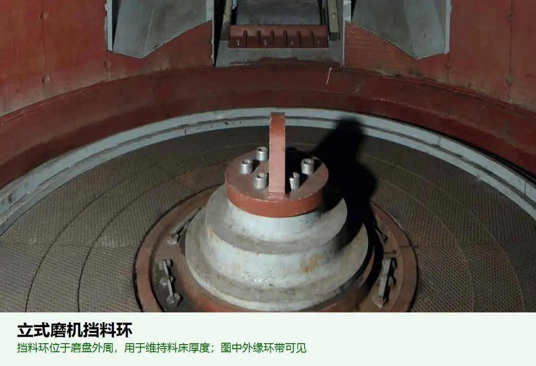
حلقة الاحتجاز / حلقة الاحتفاظ بالمادة
تضبط عمق طبقة المادة عند حافة الطاولة وتثبت الطحن. طابق الارتفاع والقطاعات والأقطار ومواضع الاتصال وموضع الطاولة والضبط مع تجهيز QMR² أو QMC² أو QMK² أو QMS² المحدد.
عرض صفحة الجزء المشترك →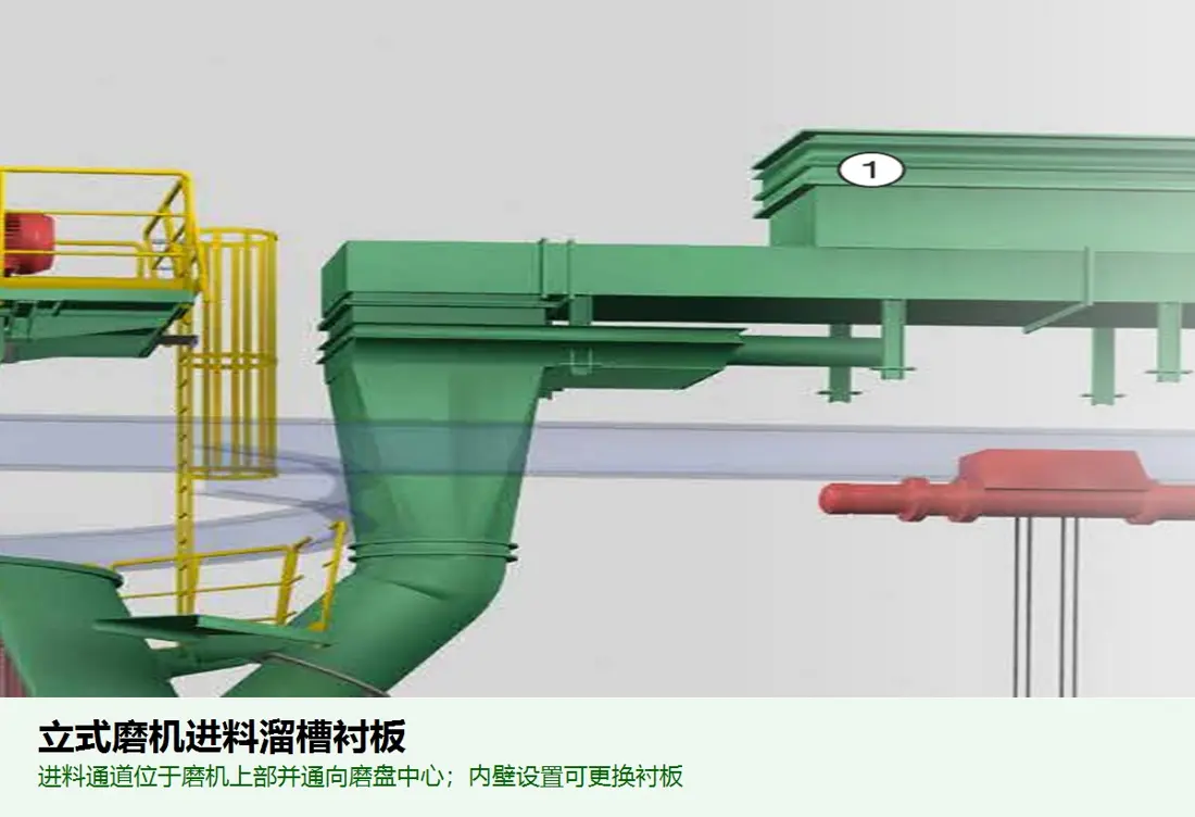
تغذية شلال بطانة
تحمي ممرات التغذية والسقوط المركزية من صدمات الكتل والتآكل الانزلاقي والتراكم. طابق المقطع والثقوب وارتفاع السقوط والميل والموضع بالنسبة لمركز الطاولة مع رسومات المزلق.
عرض صفحة الجزء المشترك →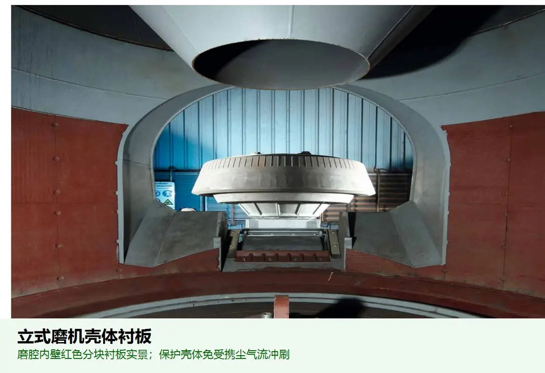
بطانة غلاف المطحنة
تحمي غلاف الحجرة وأبواب الوصول ومناطق التعرية بالهواء المحمل بالغبار. طابق المناطق والانحناءات والثقوب والتثبيت باللحام/البراغي والفتحات وتدفق الهواء مع مخططات الغلاف.
عرض صفحة الجزء المشترك →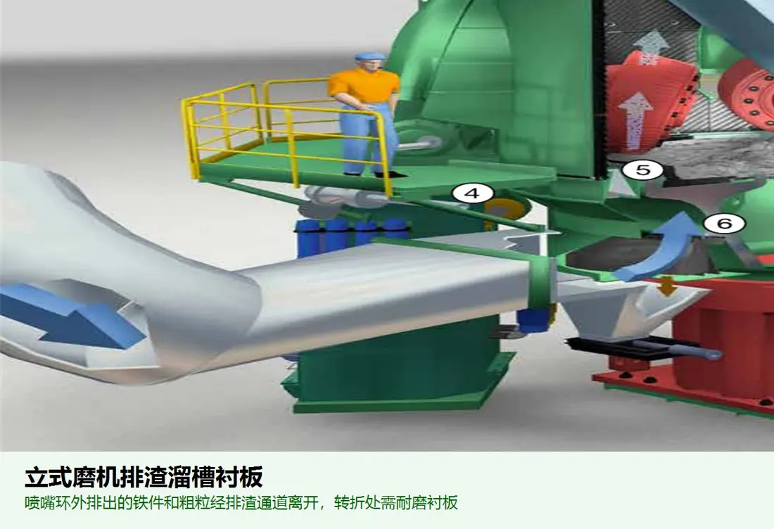
بطانة مزلق المرفوضات
تحمي ممرات الحبيبات الخشنة التي لا يحملها الهواء والمعادن الدخيلة والمرفوضات. طابق نقاط السقوط والانحناءات والأبواب والوصلات والثقوب ومواضع الاتصال التالية مع رسومات نظام الإرجاع.
عرض صفحة الجزء المشترك →افحص قطع غيار الإدارة والقطع الوظيفية بحسب السلسلة ومواضع الاتصال والأحمال والسرعة والمادة والمعالجة الحرارية وكشف العيوب والأختام والتزييت والاتزان الديناميكي.
وحدة بكرات مجمعة مسبقا
تشمل البكرة والعمود والدعامة المفصلية ومحامل الدحرجة والأسطوانة وجهاز التزييت ومواضع الاتصال. يختلف العدد والتصميم بحسب السلسلة/المشروع؛ حدد المجموعة كاملة من الرسومات.
أرسل رسومات تجميع وحدة البكرات →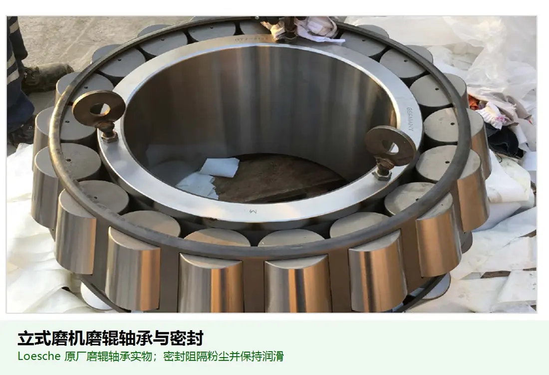
محمل البكرة & ختم الإحكام
تدعم البكرة وتمنع دخول غبار الحجرة. طابق تعيين المحمل والخلوص وعنق العمود وتجويف الغلاف والأغطية والتزييت وتصميم الختم واتجاهه مع لوحة المعدة وسجلات التركيب.
عرض صفحة الجزء المشترك →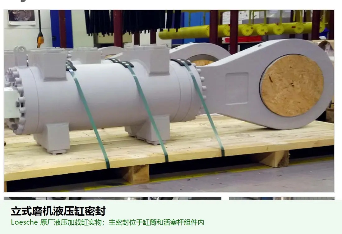
أسطوانة هيدروليكية، مركم & طقم أختام إحكام
تطبق كل أسطوانة قوة الطحن على وحدة البكرات الخاصة بها، وتخفف المراكم الأحمال. افحص معا قطر التجويف والشوط والمحاور ومسافة التركيب والضغط ومواضع الاتصال وأختام الإحكام.
عرض صفحة الجزء المشترك →علبة تروس إدارة الطاولة & وصلة
لتجهيزات QMR² وQMK² وQMC²-TD وغيرها من تجهيزات إدارة الطاولة. طابق المحرك وعلبة التروس والوصلة وشفة الخرج ودعامة الدفع واتجاه الدوران والقدرة والسرعة مع لوحات المعدات ورسومات التوصيل.
إرسال لوحات بيانات الإدارة ورسومات الواجهة →وحدة إدارة بكرة QMC²-RD
لكل بكرة QMC²-RD محرك وعلبة تروس مستقلان. افحص عدد أنظمة الإدارة وسرعة البكرة والوصلات ودعامات رد عزم الدوران ومواضع الفصل السريع والحواجز للمطحنة المحددة للمواد الأسمنتية.
أرسل سجلات نظام إدارة QMC²-RD →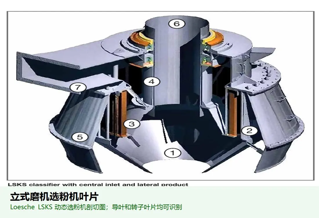
دوار الفاصل & ريشة التوجيه
تضبط نعومة المنتج في تيار هواء سريع محمل بالغبار. طابق قطر الدوار وعدد/زاوية الريش والأعمدة والبطانات ودرجة الاتزان والسرعة ومواضع اتصال غلاف المطحنة مع رسومات الفاصل.
عرض صفحة الجزء المشترك →لا. تختلف التغذية وعدد البكرات والبكرات/الطاولات وتدفق الهواء والتصنيف وأنظمة الإدارة ومتطلبات السلامة. حتى مع تشابه أرقام الطرازات، يلزم فحص الطراز الكامل والرقم التسلسلي والرسومات.
يستخدمها المصنع لتعريف الطرازات، لكن لا يتوفر هنا تعريف عام موحد يشمل جميع الأجيال. لا يفترض أي تحويل؛ تحدد الأبعاد من اللوحات والرسومات والقياسات.
لا. تلزم الأبعاد والموضع والتثبيت والمادة أو التركيب الكيميائي للعينة والصلادة وظروف التآكل ووحدة البكرات وإصدار الرسم؛ ويستخدم القياس ثلاثي الأبعاد واختبار المواد عند الحاجة.
قدم الطراز الكامل والرقم التسلسلي وعدد البكرات ونظام إدارة TD / RD والرسم وصور القطع القديمة والمادة والأبعاد والظروف لتحديد القطع وتقييم المادة والتصنيع ومراقبة الجودة والتسليم.
أو تواصل معنا مباشرة: +86 156 3797 3199
zzx@anranst.com
تقدّم ANRANST لعملائها حول العالم التقييم الهندسي والإنتاج في مسابك معتمدة وفق المتطلبات الفنية للعميل ومراقبة الجودة وتسليم القطع الجاهزة لقطع التآكل المخصّصة وقطع الغيار الصناعية، مع إمكانية دعم قطع صناعية مخصّصة أخرى.
نراجع أسطح التزاوج وأبعاد الوصلات، ونقيّم إمكانية التصنيع من حيث المادة والمعالجة الحرارية.
Material grades and heat-treatment processes are specified order by order, stated in the technical agreement and tracked through production.
تأكيد الرسم، ومراقبة المواد والعمليات، ومتابعة الإنتاج، والفحص، وتنسيق القبول.
ننسّق التصنيع وتأكيد الجودة والتغليف والتسليم للقطع الكاملة ضمن سلسلة توريد متكاملة وعملية.
Provide the equipment brand, complete model and serial number, part name, part number or drawing number, drawing revision, quantity, material requirements and duty. If identifiers are unavailable, send photographs and key dimensions.
أرسل استفساراً