
01
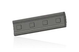
قضبان النفخ / قضبان التأثير
شريط النفخ / شريط التأثير
أجزاء التكسير الرئيسية على محيط الدوار. تحقق من القسم والطول وفتحة الدوار وأوجه التثبيت الهيدروليكي والدوران ومطابقة الكتلة مقابل رسومات الطراز PB الكاملة والدوار.
عرض صفحة الجزء المشترك →نطاق الكسارة التصادمية Polysius الحالي: تحديد أجزاء التآكل وقطع الغيار وأدوات الصيانة حسب الطراز الأساسي/الثانوي وقطر دائرة التصادم وعرض الدوار وموضع التثبيت.
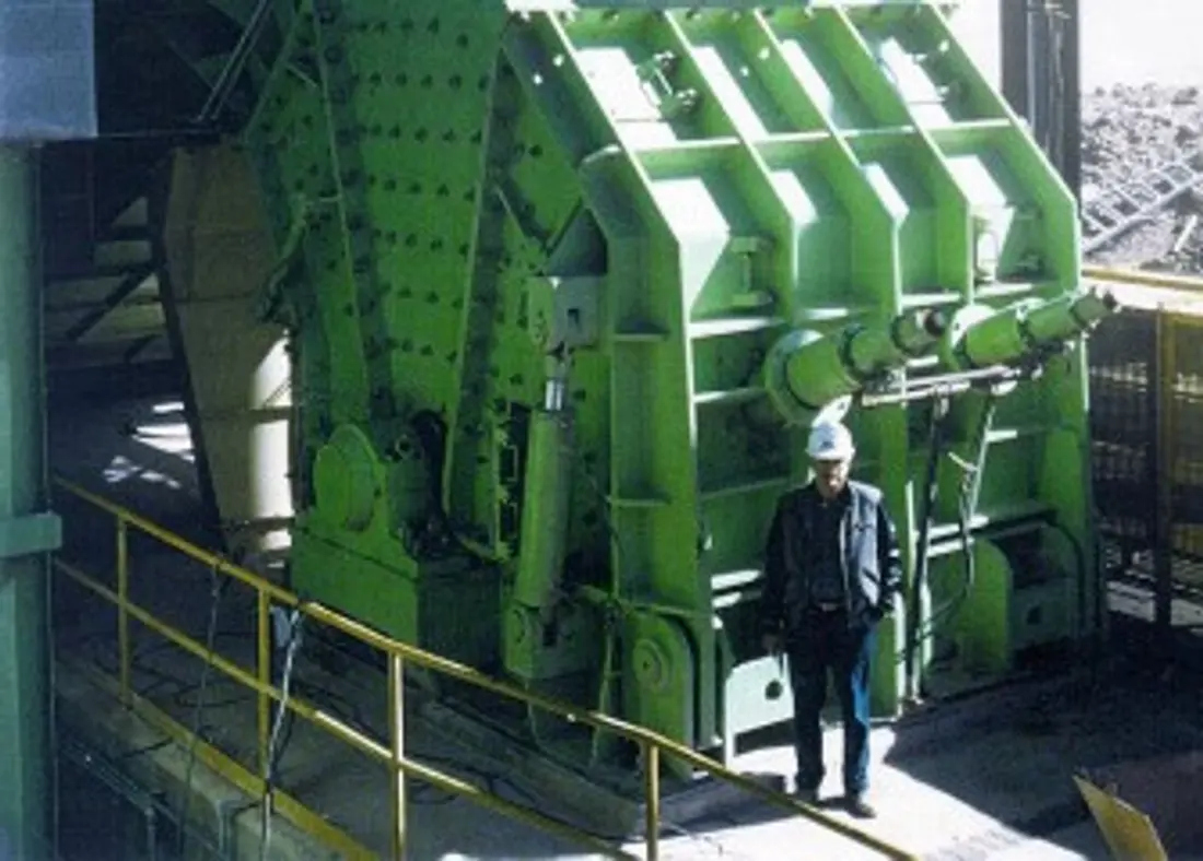
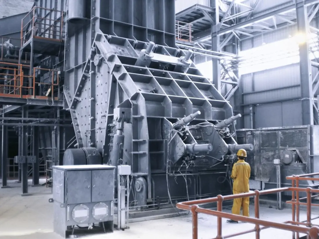
تقوم الكسارات PB بسحق أولي أو ثانوي للتغذية المتوسطة الصلابة إلى الصلبة في ترتيبات ثابتة أو شبه متحركة أو متنقلة. تركز هذه الصفحة على الطرازات القياسية والأبعاد الأساسية ومواضع الأجزاء والمواد والفحوصات الفنية اللازمة لإمدادات الغيار.
يتبع الجدول كتيب الكسارات التصادمية thyssenkrupp: إدخالات 11 الأولى هي طرازات PB الأولية … CR وطرازات 9 التالية هي طرازات PB الثانوية. تعتمد الإنتاجية على المواد ومتطلبات المنتج والتكوين.
| الطراز القياسي | قطر دائرة التأثير | عرض الدوار | فتح التغذية | الإنتاجية المرجعية |
|---|---|---|---|---|
| PB 160/150 CR | 1600 mm | 1500 mm | 1410 × 1520 mm | 400 t/h |
| PB 160/200 CR | 1600 mm | 2000 mm | 1410 × 2020 mm | 650 t/h |
| PB 180/200 CR | 1800 mm | 2000 mm | 1640 × 2030 mm | 800 t/h |
| PB 180/250 CR | 1800 mm | 2500 mm | 1640 × 2530 mm | 1000 t/h |
| PB 200/200 CR | 2000 mm | 2000 mm | 1845 × 2030 mm | 1100 t/h |
| PB 200/250 CR | 2000 mm | 2500 mm | 1845 × 2530 mm | 1300 t/h |
| PB 200/300 CR | 2000 mm | 3000 mm | 1845 × 3030 mm | 1500 t/h |
| PB 220/250 CR | 2200 mm | 2500 mm | 1950 × 2530 mm | 1700 t/h |
| PB 220/300 CR | 2200 mm | 3000 mm | 1950 × 3030 mm | 2000 t/h |
| PB 250/250 CR | 2500 mm | 2500 mm | 2150 × 2530 mm | 1850 t/h |
| PB 250/300 CR | 2500 mm | 3000 mm | 2150 × 3030 mm | 2500 t/h |
| PB 100/100 | 1000 mm | 1000 mm | 710 × 1060 mm | 110 t/h |
| PB 100/125 | 1000 mm | 1250 mm | 710 × 1310 mm | 145 t/h |
| PB 125/125 | 1250 mm | 1250 mm | 950 × 1310 mm | 230 t/h |
| PB 125/150 | 1250 mm | 1500 mm | 950 × 1560 mm | 275 t/h |
| PB 140/150 | 1400 mm | 1500 mm | 1000 × 1560 mm | 330 t/h |
| PB 140/175 | 1400 mm | 1750 mm | 1000 × 1810 mm | 400 t/h |
| PB 140/200 | 1400 mm | 2000 mm | 1000 × 2060 mm | 450 t/h |
| PB 140/250 | 1400 mm | 2500 mm | 1000 × 2560 mm | 550 t/h |
| PB 140/300 | 1400 mm | 3000 mm | 1000 × 3060 mm | 650 t/h |
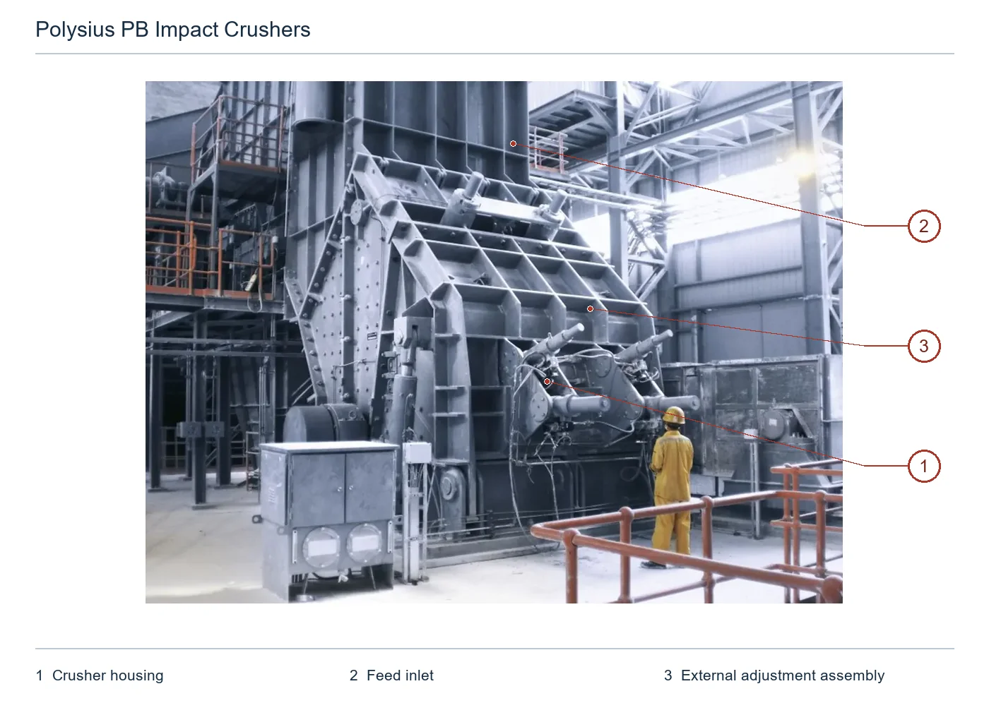
تتطابق الأرقام على المخطط مع الصفوف أدناه.
| الرقم | المكوّن | الموضع | ينطبق على |
|---|---|---|---|
| 1 | غلاف الكسارة | غلاف كسارة مرتفع في المركز | PB 220/300 |
| 2 | مدخل التغذية | مدخل تغذية فوق غلاف الكسارة | PB 220/300 |
| 3 | مجموعة ضبط خارجية | مجموعة ضبط ظاهرة يمين الغلاف | PB 220/300 |
تواجه الأوضاع المختلفة تأثيرا عالي الطاقة، أو الارتداد المتكرر، أو التآكل المنزلق، أو تآكل الحواف. ترتبط كل بطاقة بصفحات المكونات والمواد المشتركة.
شريط النفخ / شريط التأثير
أجزاء التكسير الرئيسية على محيط الدوار. تحقق من القسم والطول وفتحة الدوار وأوجه التثبيت الهيدروليكي والدوران ومطابقة الكتلة مقابل رسومات الطراز PB الكاملة والدوار.
عرض صفحة الجزء المشترك →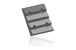
بطانة حاجز الصدم الأول
يستقبل المواد ذات الطاقة العالية التي يتم إلقاؤها من الدوار. تحقق من الانحناء والأقسام والثقوب والتثبيت وخلوص الدوار وفقا لرسومات الهيكل والمئزر.
عرض صفحة الجزء المشترك →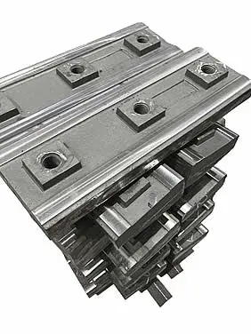
بطانة سطح الصدم السفلي
في مناطق التأثير والتشكيل اللاحقة، تواجه البطانات تأثيرا متكررا وتآكلا انزلاقيا. تختلف ملفات التعريف والعروض والتداخلات وعلاقات ضبط الفجوة بين المراحل ولا يمكن الخلط بينها.
عرض صفحة الجزء المشترك →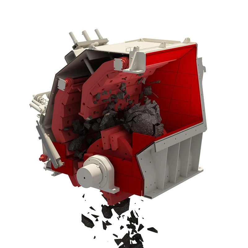
بطانة جانبية
قم بحماية جوانب الدوار وجدران الهيكل أثناء تنظيف عملية مسح قضيب النفخ. تحقق من الأجزاء اليسرى/اليمنى، والثقوب، والسمك، وتسلسل التجميع، ومواضع باب الوصول مقابل رسومات التثبيت.
عرض صفحة الجزء المشترك →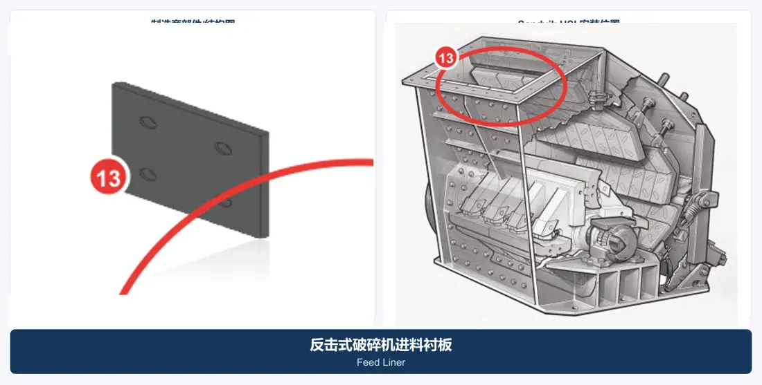
تغذية & بطانة الغلاف
قم بتغطية نقاط تأثير التغذية وجدران السكن والانتقالات. تحقق من مناطق الانزلاق وصدمات السقوط بشكل منفصل بدلا من افتراض السماكة والمواد نفسها.
عرض صفحة الجزء المشترك →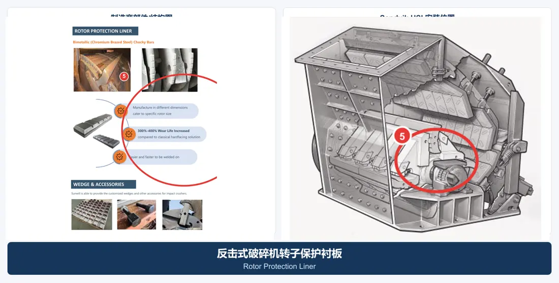
بطانة حماية الدوار
قم بحماية الأقراص الطرفية والمناطق المحيطة بفتحات قضيب النفخ. تحقق من المظهر الجانبي النهائي والقطاعات والثقوب وخلوص التثبيت وتأثيرات التوازن الديناميكي باستخدام رسم مجموعة الدوار.
عرض صفحة الجزء المشترك →تحقق من نظام الإدارة والأجزاء الوظيفية بشكل منفصل لمعرفة الأبعاد والواجهات والأحمال والمواد والمعالجة الحرارية واكتشاف العيوب والتصنيع والتجميع.
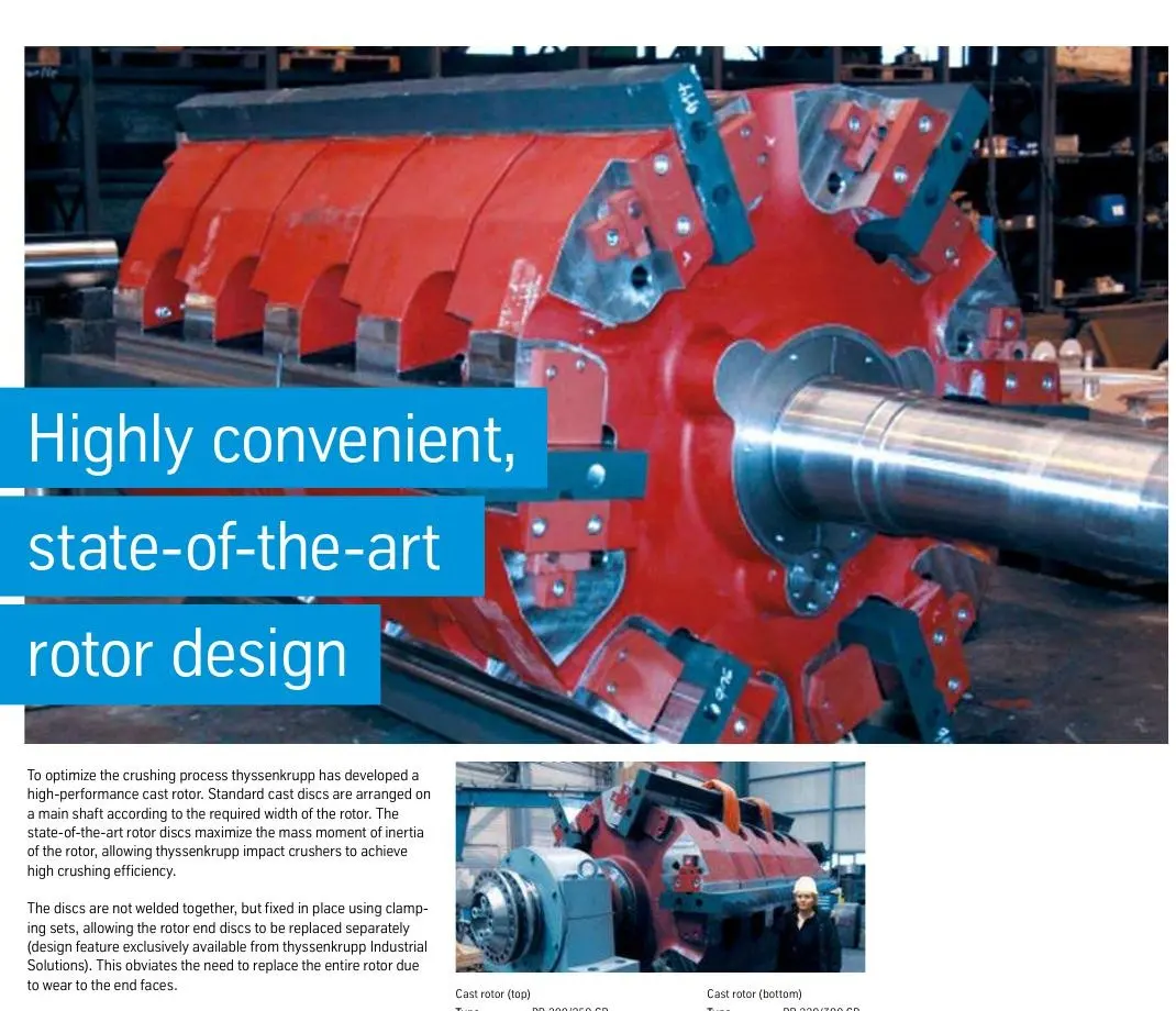
تجميع الدوار المصبوب
تظهر سجلات الشركة المصنعة العمود الرئيسي، وأقراص الدوار المصبوب المنفصلة، والأقراص الطرفية، وفتحات قضيب النفخ، والمشابك. تحقق من القطر والعرض ومكدس القرص ومطابقة الكتلة والتوازن الديناميكي وواجهات المحمل معا بواسطة طراز PB.
عرض صفحة الجزء المشترك →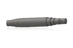
عمود الدوار
يمر عبر الأقراص وينقل عزم الدوران الكامل. تحقق من أعناق الأعمدة، والخطوات، والمفاتيح/التوصيلات، وملاءمة الأطراف، وتدفق الانحناء، وواجهات المحمل/الاقتران مقابل الرسومات الأصلية.
عرض صفحة الجزء المشترك →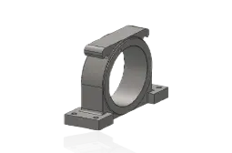
محمل الدوار & الغلاف
دعم الدوارات الثقيلة تحت التأثير وعدم التوازن. تحقق من تعيين المحمل، والتخليص، وتجويف المبيت، والأغطية الطرفية، والأختام، والتشحيم، والاتجاه الأيسر/الأيمن مقابل سجلات التثبيت.
عرض صفحة الجزء المشترك →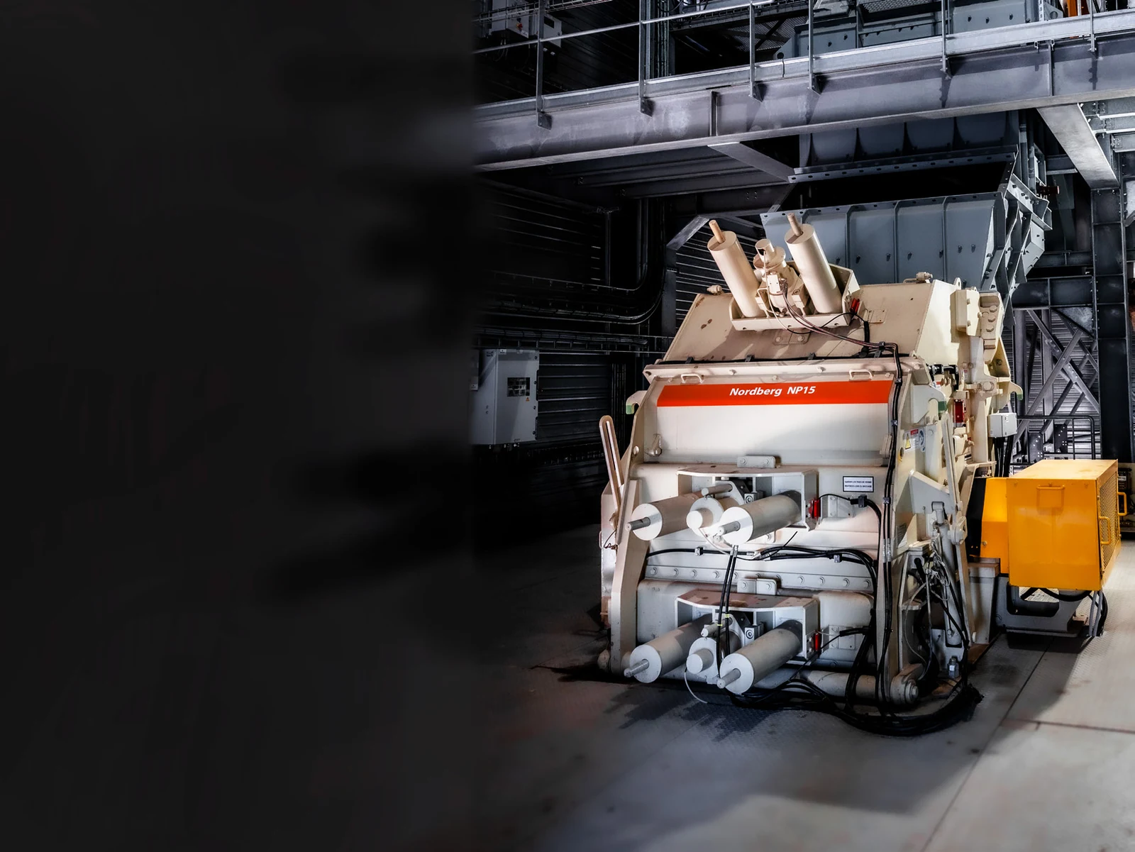
اسطوانة تعديل الفجوة الهيدروليكية
يتم توفير التحميل المسبق وضبط الفجوة وإطلاق التحميل الزائد لأسطح الصدمات ومسارات الطحن. تحقق من التجويف والشوط ومسافة التركيب والدبابيس والضغط والمنافذ والأختام كمجموعة.
عرض صفحة الجزء المشترك →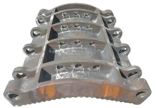
مجموعة لوح الصدم
يشتمل على الإطار، والبطانات، والعمود المحوري، وقضبان الضبط، والتحميل الهيدروليكي المسبق. تحقق من أبعاد الإطار والمراكز المحورية وتخطيط البطانة ونطاق الفجوة كتجميع.
عرض صفحة الجزء المشترك →
الإسفين الهيدروليكي & الأجزاء المحتجزة
تستخدم الشركة المصنعة التثبيت الهيدروليكي لتأمين قضبان النفخ وتبسيط عملية الانعكاس/الاستبدال. تحقق من زاوية الإسفين وأوجه التلامس ونقاط التحميل الهيدروليكية والمثبتات وفتحات الدوار معا.
عرض صفحة الجزء المشترك →لا. تحقق من الرقم التسلسلي، وتصميم الدوار، وقسم قضيب النفخ وطوله، وإسفين التثبيت، والتدوير، والرسم والمراجعة.
لا تفترض ذلك. تختلف طاقة التأثير، والتآكل المنزلق، وخطر الكسر، وفترات التثبيت والاستبدال. حدد المواد بشكل منفصل حسب المنصب وظروف التشغيل.
لا. الإنتاجية تدعم التعريف الأولي فقط. يتطلب التصنيع طرازا كاملا أو لوحة اسمية أو رسما أو أبعادا مقاسة أو رسومات معتمدة.
يتم توفير طراز PB، والرقم التسلسلي، وأبعاد الدوار، وقسم قضيب النفخ، والمئزر، والرسم، وصور الأجزاء المستخدمة، والمواد وشروط التعريف، وتقييم المواد، والتصنيع، ومراقبة الجودة والتسليم.
أو تواصل معنا مباشرة: +86 156 3797 3199
zzx@anranst.com
تقدّم ANRANST لعملائها حول العالم التقييم الهندسي والإنتاج في مسابك معتمدة وفق المتطلبات الفنية للعميل ومراقبة الجودة وتسليم القطع الجاهزة لقطع التآكل المخصّصة وقطع الغيار الصناعية، مع إمكانية دعم قطع صناعية مخصّصة أخرى.
نراجع أسطح التزاوج وأبعاد الوصلات، ونقيّم إمكانية التصنيع من حيث المادة والمعالجة الحرارية.
Material grades and heat-treatment processes are specified order by order, stated in the technical agreement and tracked through production.
تأكيد الرسم، ومراقبة المواد والعمليات، ومتابعة الإنتاج، والفحص، وتنسيق القبول.
ننسّق التصنيع وتأكيد الجودة والتغليف والتسليم للقطع الكاملة ضمن سلسلة توريد متكاملة وعملية.
Provide the equipment brand, complete model and serial number, part name, part number or drawing number, drawing revision, quantity, material requirements and duty. If identifiers are unavailable, send photographs and key dimensions.
أرسل استفساراً