thyssenkrupp Polysius بكرات الطحن عالية الضغط polycom®

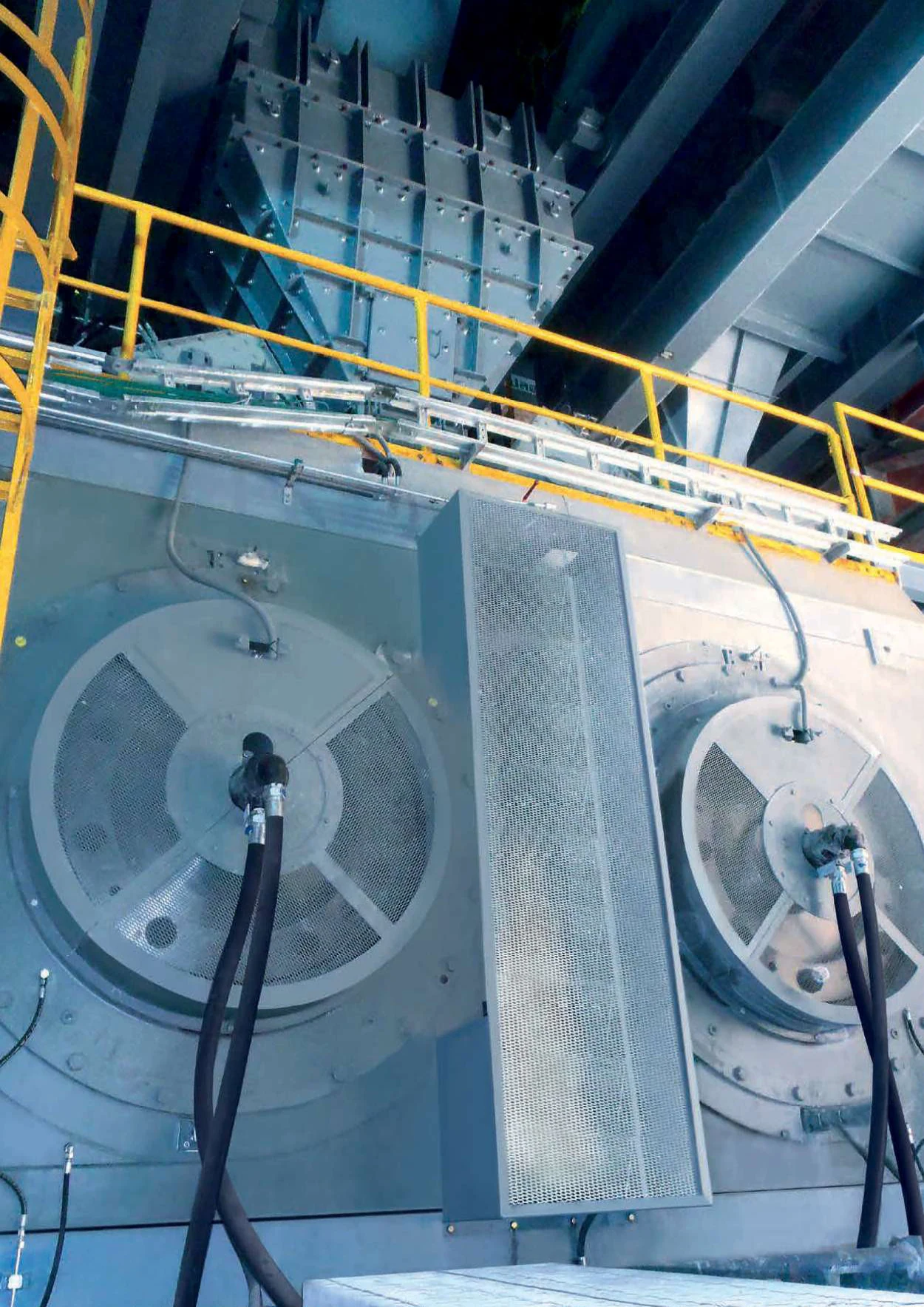
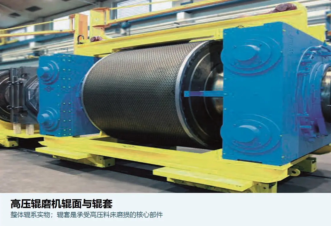
The current Polysius high-pressure bed-grinding range: identify wear, bearing, hydraulic and drive parts by project configuration, roll design, diameter/width and installation position.

thyssenkrupp Polysius polycom HPGR manufacturer image
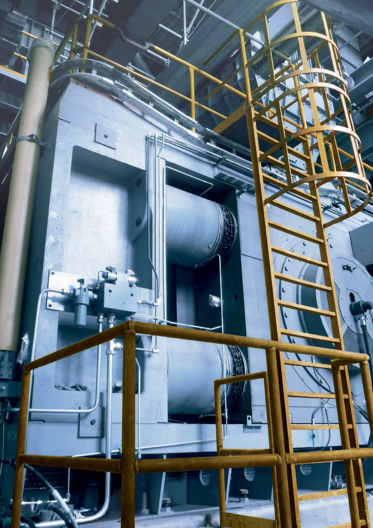
Manufacturer polycom® roll-unit and hydraulic image locating fixed and floating rolls, bearings and pressure system.
Polysius polycom bearing, hydraulic and roll-shaft area
Manufacturer close-up of shaft ends, bearing housings, hydraulic cylinders and frame connections.
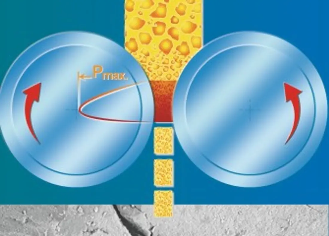
polycom high-pressure bed-comminution diagram
Manufacturer high-pressure bed-comminution principle: counter-rotating rolls compact material at high pressure in the gap, causing interparticle breakage.
OEM المعدات Reference

Installation configurations, roll wear systems and core spares on one page

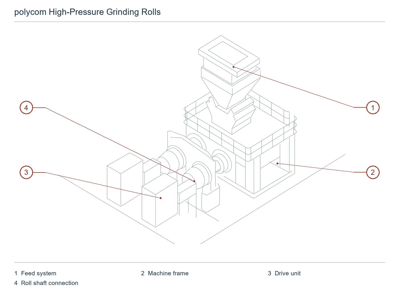
polycom® is customized for material, output and process rather than sold through uniform public model codes. Published configurations, historical installation size ranges and roll, bearing, hydraulic and drive data support spare identification against actual machine records.

> 2000 t/h Current website's published maximum capacity class
≤ 60 mm Current website's published maximum feed size
Up to 250 MPa Roll-gap pressure in raw-material grinding brochure
3 Published roll-surface wear concepts
Standard Models and Key Dimensions

Published polycom® configurations and installation ranges

The current website describes project-specific polycom® configurations without uniform model codes. The table lists only traceable current configurations and historical mineral-HPGR dimensions.

Published configuration / installation rangeRoll diameter / identification rangeRoll width / configurationCapacity and applicationProduct status
polycom® raw-material finish grindingCustomized by material and outputProject-specificPublished maximum capacity exceeds 2000 t/h; maximum feed size 60 mmCurrent product
polycom® cementitious-material finish grindingCustomized for cement clinker, slag and other materialsProject-specificPaired with sepol® classificationCurrent product
polycom® pregrinding / combined grindingAdapted to the existing ball mill circuitProject-specificCapacity-expansion and energy-saving retrofitsCurrent product
Polysius mineral HPGR installed rangeRoll diameter 0.5–2.8 mRoll width 0.2–1.8 m20 to over 2500 t/h; 2 × 50 to 2 × 3000 kWHistorical technical-data range

Before manufacture, confirm nameplate, serial number, roll diameter/width, fixed/floating position, surface design, bearings, hydraulics, drive, drawing number and revision.

قطع الغيار المستهلكة

Roll bodies, studs, cheek plates and chute wear parts

Roll surfaces, studs, edges, cheek plates and chutes face different pressure, impact and wear mechanisms. Confirm materials and processes separately by position.

Forged or hardfaced roll-body identification image
01

Forged / Hardfaced أجسام الأسطوانات

Forged / Welded Roll Body

Hardfaced profiles retain a material bed for autogenous wear protection. Confirm diameter, width, hardfacing type, pattern, hard layer and edge design against installation drawings.

Material selection: Core, transition and hardfacing layers are separate material/process systems. Define them using specific wear, pressure, repair interval and site welding conditions.

View the common part page →
Compound-cast roll-body identification image
02

Compound-Cast أجسام الأسطوانات

Compound-Cast Roll Body

A tough core and high-compressive-strength outer layer serve high-specific-wear duties. Confirm layer thickness, interface, profile, ends and shaft assembly as a complete roll unit.

Material selection: Compound casting requires control of core toughness, outer-layer compression/wear resistance, metallurgical bonding, heat treatment and nondestructive examination, not hardness alone.

View the common part page →
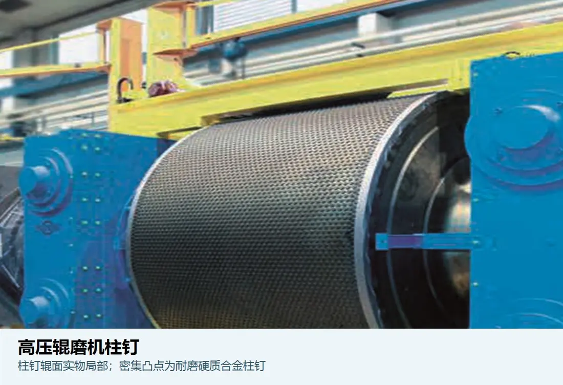
Carbide-studded roll-surface identification image
03

Carbide-Studded Roll Surfaces

Hard-Metal Studded Roll Surface

Studs retain a protective material bed. Diameter, length, density, pattern, edge zones and hole fits vary with roll and feed.

Material selection: Studs use carbide systems. Roll-body holes require strength, toughness and crack resistance; installation/replacement must control interference, hole quality and edge protection.

View the common part page →
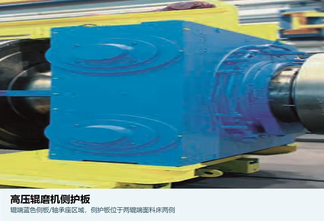
Cheek-plate and side-liner identification image
04

Cheek Plates / البطانة الجانبية

Cheek Plate / Side Liner

Limit lateral escape from the roll gap and stabilize the feed column. Check profile, thickness, clearance, supports, left/right position and edge wear zones by roll diameter and width.

Material selection: Face lateral compression from high-pressure material and abrasion. Assess wear plate, alloy steel or reinforced composites, controlling edge crack resistance and dimensions.

View the common part page →
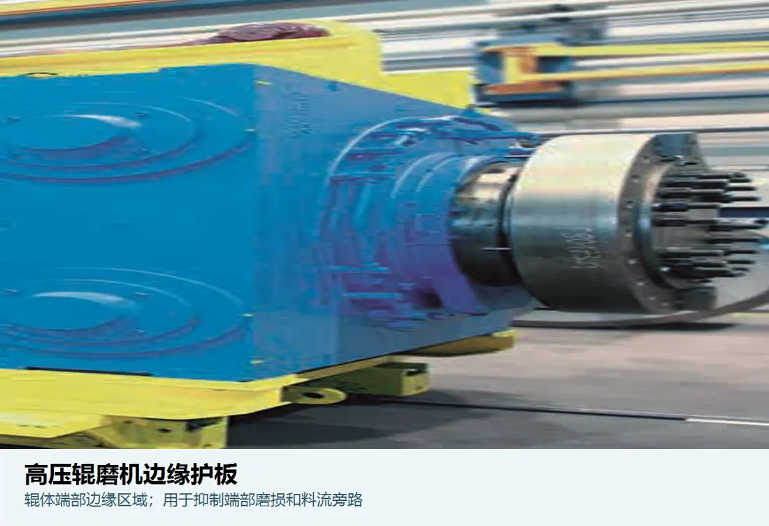
Roll-edge protection identification image
05

Roll Edge Protection

Roll Edge Protection

Protect high-wear roll ends against spalling and side leakage. Confirm segments, fastening, end faces, overlaps with stud zones and left/right roll position against original drawings.

Material selection: Edges face impact, shear and stress concentration. Tough wear alloys, carbide inserts or composites require validation of chipping resistance.

View the common part page →
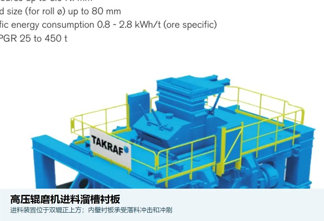
Feed-chute liner identification image
06

Feed Chute Liners

بطانة مزلق التغذية

Cover feed drop points and the material column, supporting uniform feeding and protecting the chute shell. Confirm holes, joints, drop height, access and cheek-plate interfaces against chute drawings.

Material selection: Select wear plate, rubber or polyurethane composites by size, drop height, moisture and impact-wear zones; check blockage and delamination risks.

View the common part page →
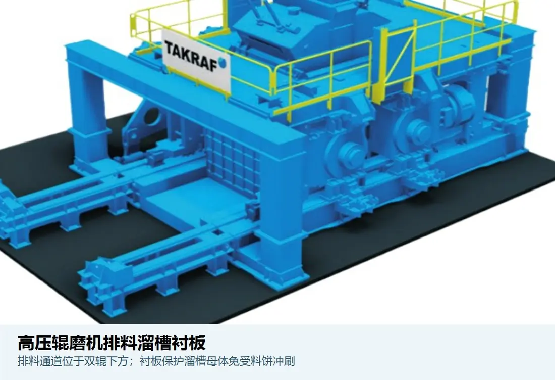
Discharge-chute liner identification image
07

بطانات قناة التفريغ

بطانة قناة التفريغ

Protect cake-discharge and transfer passages against sliding wear, local impact and buildup. Confirm profile, holes, joints, slope and downstream interfaces against discharge-chute drawings.

Material selection: Select wear plate or elastic composite liners against cake strength, moisture, speed and clearing methods, controlling joint, edge and fastener wear.

View the common part page →
قطع الغيار

Roll units, bearings, hydraulics, drives and lubrication spares

Check drive and functional parts individually for interfaces, loads, materials, heat treatment, flaw detection, machining, sealing and system parameters.

Machine image locating the fixed-roll unit
01

Fixed Roll Units

Fixed Roll Unit

Roll body, mainshaft, bearings, seals and end interfaces are fixed on one frame side. Confirm diameter, width, journals, supports, drive end and surface design as an assembly.

Material selection: Large roll shafts, bearing fits, wear surfaces, heat treatment, flaw detection and dynamic balance require one coordinated manufacturing and acceptance plan.

Submit fixed-roll assembly drawings →
Machine image locating the floating-roll unit
02

Floating Roll Units

Floating Roll Unit

Moves along guides under hydraulic cylinders to generate grinding force. Besides rolls and bearings, check sliding guides, pressure beams, cylinder mounts, stops and skew-control interfaces together.

Material selection: Select materials, heat treatment and surface strengthening separately for roll shafts, guides and force-transfer parts against impact, contact stress, fatigue and slow-speed heavy loads.

Submit floating-roll assembly drawings →
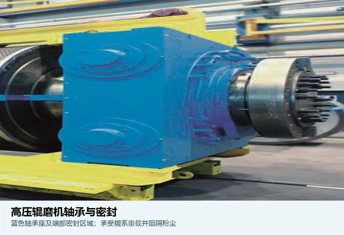
Roll bearing and seal identification image
03

Roll المحامل والموانع

Roll Bearing & Seal

Carry high grinding forces, impact and skew loads. Confirm bearing designation, clearance, housing bore, covers, labyrinths, oil seals, lubrication and left/right position against installation records.

Material selection: Procure bearings to original designation and clearance. Select seals for lubricant, dust, temperature, speed and journal condition; similar appearance is not sufficient.

View the common part page →
Hydraulic cylinder and seal-set identification image
04

Hydraulic Cylinders and Seal Sets

Hydraulic Cylinder & Seal Set

Apply preload and grinding force to the floating roll, working with accumulators to absorb load fluctuations. Check bore, stroke, mounting distance, pins, pressure and interfaces as a set.

Material selection: Confirm barrels, rods, pins, seals and surfaces against high pressure, side load, contamination and temperature; conduct dimensional and pressure tests after repair.

View the common part page →
Machine image locating gearbox, coupling and torque support
05

Drive Gearboxes, Couplings and Torque Supports

Drive علبة التروس, Coupling & Torque Support

Rolls are usually driven separately. Confirm motors, gearboxes, couplings, hollow-shaft or shaft-end connections, torque supports and guards together by power, speed, rotation and interfaces.

Material selection: Manufacture or source gears, shafts, couplings and supports to torque, impact, fatigue, tooth loading, heat treatment, flaw detection and dynamic-balance requirements.

Submit drive nameplates and interface drawings →
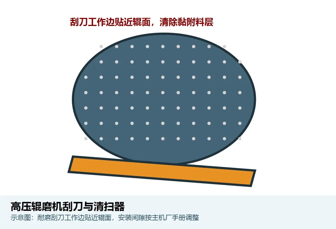
Scraper-system identification image
06

Lubrication, Cooling and Scraper Systems

Lubrication, Cooling & Scraper System

Includes bearing lubrication, cooling lines, filtration, monitoring and roll/discharge cleaning parts. Check pumps, valves, filters, nozzles, scrapers and instruments against medium and schematics.

Material selection: Select scraper wear metals or elastic materials for contact wear; select seals, hoses and filters for pressure, temperature, oil and contamination class.

View the common part page →

Why is no uniform polycom® model-code list invented here?

Current manufacturer pages explicitly configure machines for material, process and project requirements without a uniform public model table. Identification requires nameplate, roll diameter/width, surface design, serial number and drawings.

Are studded, compound-cast and hardfaced rolls directly interchangeable?

No. Roll construction, pressure, specific wear, edge protection, maintenance and project configuration differ. Assess the complete roll unit and operating conditions.

Are roll diameter and width enough to manufacture bearings or hydraulic parts?

No. Confirm fixed/floating position, journals and housing bores, bearing designation, clearance, cylinder dimensions and pressure, seals, interfaces and drawing revision.

Submit polycom® nameplate, roll, hydraulic and drawing records

Provide serial number, roll diameter/width, surface design, fixed/floating position, bearing and hydraulic nameplates, drawing number, used-part photos, material and conditions for identification, material assessment, manufacture, quality control and delivery.

Submit التفاصيل for a Quote

رقم الهاتف: +86 156 3797 3199
zzx@anranst.com

خدمات صنع في الصين

من التقييم الفني إلى تسليم المنتج بالكامل

توفر شركة ANRANST للعملاء العالميين تقييمات هندسية، واختيار التصنيع الصيني، ومراقبة الجودة، وتسليم الأجزاء النهائية لقطع الغيار الصناعية المقاومة للتآكل حسب الطلب، ويمكنها أيضًا دعم قطع الغيار الصناعية الأخرى حسب الطلب.

01

مراجعة الرسومات والهندسة

قم بمراجعة أسطح التزاوج وأبعاد الواجهة، وقم بتقييم جدوى المواد والمعالجة الحرارية والتصنيع.

02

تحديد المادة والمعالجة الحرارية

تُحدَّد درجات المواد وعمليات المعالجة الحرارية لكل طلب على حدة، وتُثبَّت في الاتفاقية الفنية وتُتابَع أثناء الإنتاج.

03

ضبط الجودة

يشمل ذلك تأكيد الرسم، ومراقبة المواد والعمليات، وتتبع الإنتاج، وتنسيق عمليات الفحص والقبول.

04

تسليم المنتج النهائي

تنظيم عمليات التصنيع والتحقق من الجودة والتعبئة والتغليف وتسليم المنتجات النهائية الكاملة لتشكيل حلقة إمداد قابلة للتنفيذ.

قم بتزويدنا بالنماذج الحالية، والرسومات، وأرقام الرسومات، وأرقام الأجزاء، والمواد، أو معلومات ظروف التشغيل، وسنقوم بتحديد التحقق الفني ومسار التوريد وفقًا لذلك.

إرسال طلب