
01
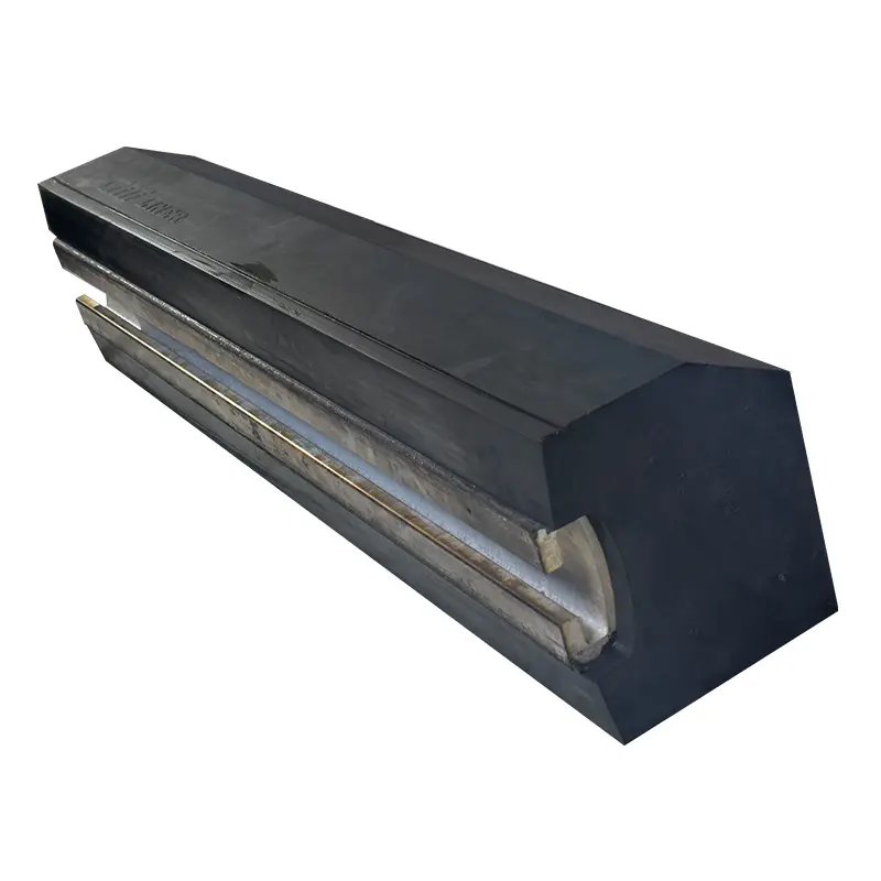
بطانات رفع / تنشيط الحجرة الأولى
بطانة رفع / تنشيط الحجرة الأولى
تعمل مع كرات كبيرة لتوفير الرفع والصدم. طابق المقطع وزاوية الرفع والقطاعات والسماكة والثقوب والبراغي والدوران مع توزيع بطانات الغلاف.
عرض صفحة الجزء المشترك →تصاميم ثنائية الحجرة وأحادية الحجرة ومجتاحة بالهواء ومرتكزة على الغلاف، مع بطانات وحواجز وحلقات انزلاق وأحذية انزلاق وإدارة بالتروس ودعم صيانة ميداني.
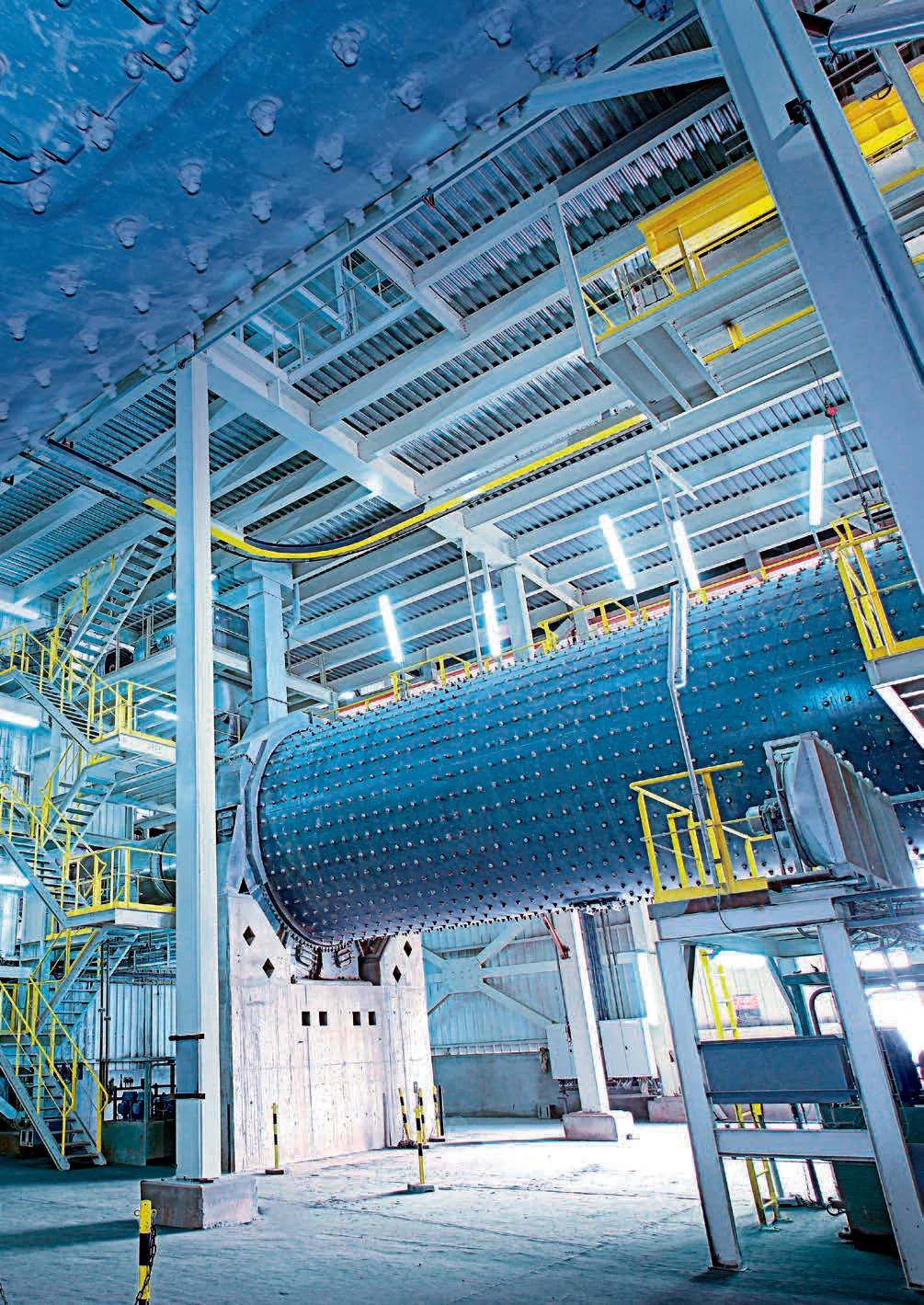
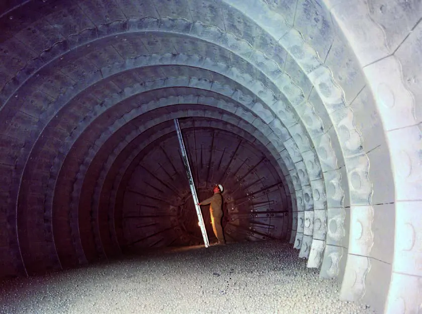
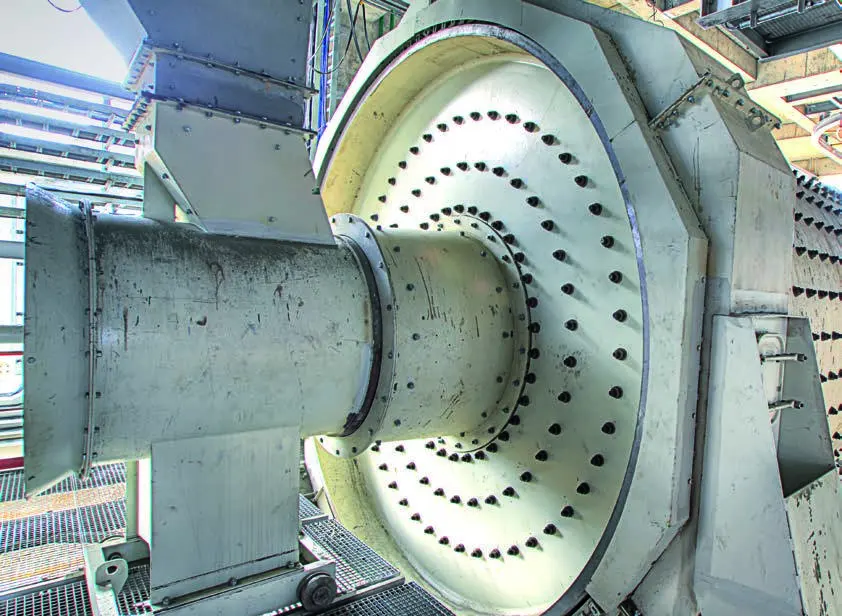
تجهز مطاحن Polysius الكروية بحسب المشروع والمادة والتغذية ودائرة الطحن والدعم والإدارة. لا ينشر الموقع الحالي وكتيبات المصنع جدولا موحدا للطرازات والأحجام. تسرد الصفحة تصاميم وأداء قابلة للتتبع دون اختراع طرازات أو أقطار.
يبين الموقع الحالي استمرار توريد المنتج؛ وتأتي بيانات الهيكل والإدارة من كتيب المصنع لعام 2018. عند عدم نشر رمز طراز موحد، تدرج فقط التجهيزات والمعلمات القابلة للتتبع.
| النوع / التجهيز المنشور | البنية والاستخدام | الأبعاد / المعلمات الرئيسية | مواضع توصيل النظام | حالة المنتج |
|---|---|---|---|---|
| مطحنة كروية ثنائية الحجرة بدائرة مغلقة | طحن خشن في الحجرة الأولى وناعم في الثانية؛ ينظم الحاجز الوسطي تدفق المادة | أقصى قطر كرة منشور للحجرة الأولى 100 mm | يمكن تشكيل دائرة مغلقة مع فاصل عالي الكفاءة sepol® | الموقع الحالي وكتيب المصنع لعام 2018 |
| مطحنة كروية أحادية الحجرة | لتغذية أنعم؛ قد تعمل كمرحلة طحن ثانية بعد الطحن الأولي | تفريغ ميكانيكي عبر حاجز التفريغ | يمكن تشكيل نظام طحن مركب مع بكرة طحن بالضغط العالي polycom® | كتيب المصنع لعام 2018 |
| مطحنة مجتاحة بالهواء | تصميم أحادي الحجرة لمواد رطبة تتطلب تجفيفا بغاز منخفض الحرارة | تفريغ هوائي مباشر إلى فاصل يعمل بالهواء | للفحم أو فحم الكوك البترولي عند تجهيز نظام حماية مناسب من الانفجار | كتيب المصنع لعام 2018 |
| مطحنة كروية مرتكزة على الغلاف | يرتكز الغلاف على حلقات انزلاق ومحامل أحذية ورفع هيدروليكي | تستخدم كل مجموعة محامل 2 أو 4 أو 6 أحذية بحسب حجم المطحنة | تزييت هيدروستاتيكي أو هيدروديناميكي للأحذية بحسب الحمل | كتيب المصنع لعام 2018 |
| نظام الإدارة COMBIFLEX® | إدارة مطحنة عالية القدرة بأعمدة عائمة وتروس مقساة | الحد الأقصى المنشور 8,000 kW بإدارة واحدة؛ 16,000 kW بإدارة مزدوجة | يشغل الترس الحلقي وحلقة الانزلاق وأحذيته منطقة غلاف مدمجة واحدة | كتيب المصنع لعام 2018 |
| إدارة مباشرة بالتروس | إدارة بترس حلقي وترس صغير للمطاحن الأقل قدرة | لا يوجد جدول موحد للطرازات بالقدرة أو القطر في الكتيب العام | افحص الترس الحلقي والترس الصغير والمحامل والوصلات والمحاذاة كمجموعة | كتيب المصنع لعام 2018 |
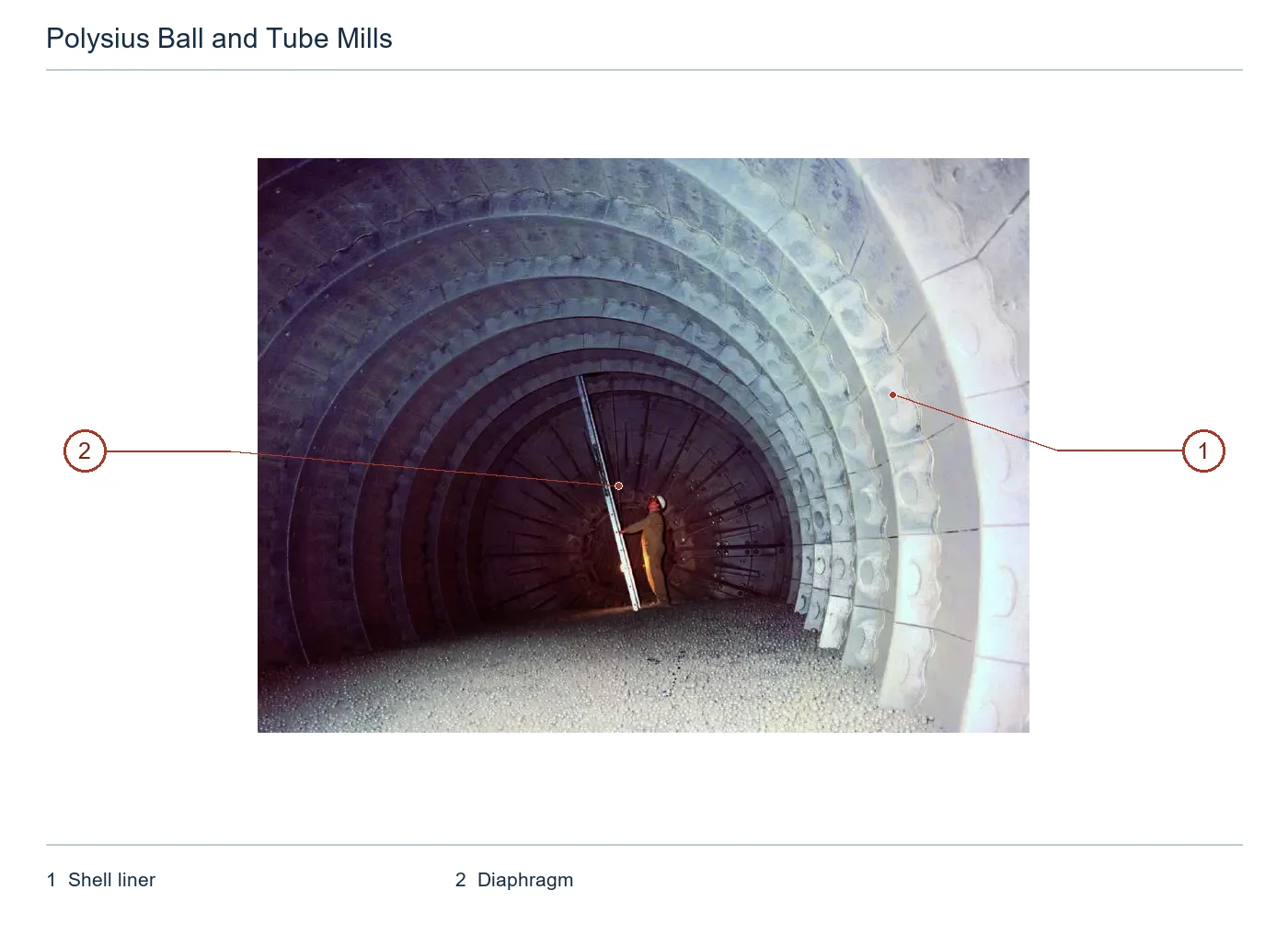
تتطابق الأرقام على المخطط مع الصفوف أدناه.
| الرقم | المكوّن | الموضع | ينطبق على |
|---|---|---|---|
| 1 | بطانة الأسطوانة | صفوف بطانات الأسطوانة على الجدار الأسطواني الداخلي يمينا | Polysius tube mill |
| 2 | Diaphragm | حاجز شعاعي عند الطرف البعيد لحجرة الطحن | Polysius tube mill |
تنتج الصدمات في الحجرة الأولى والطحن الناعم في الثانية وتدفق الحاجز وتعرية التغذية والتفريغ أنماط تلف مختلفة. طابق المواد والمقاطع والشقوق والتصنيع منفصلة بحسب الموضع.
بطانة رفع / تنشيط الحجرة الأولى
تعمل مع كرات كبيرة لتوفير الرفع والصدم. طابق المقطع وزاوية الرفع والقطاعات والسماكة والثقوب والبراغي والدوران مع توزيع بطانات الغلاف.
عرض صفحة الجزء المشترك →بطانة تصنيف الحجرة الثانية
تصنف وسائط الطحن الأصغر على طول المطحنة للطحن الناعم. طابق المقطع واتجاه التصنيف والثقوب والقطاعات وسماحية التآكل ومواضع اتصال الحاجز مع رسومات التركيب.
قدم رسومات بطانات الحجرة الثانية →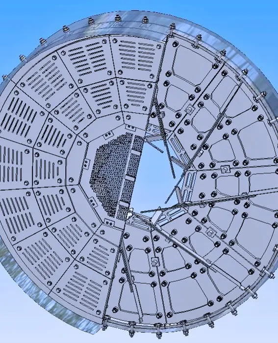
حاجز وسطي & لوح تآكل
يفصل حجرتي الطحن الخشن والناعم وينظم معدل المرور. طابق الإطار والشقوق والفتحة المركزية وألواح التآكل والمغارف والتثبيت وملء وسائط الطحن مع رسم مجموعة الحاجز.
قدم رسومات مجموعة الحاجز →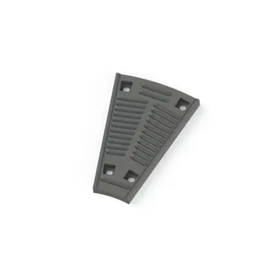
حاجز تفريغ / شبكة مركزية
يوفر تفريغا ميكانيكيا ويضبط ممرات الخروج. طابق الشقوق والمساحة الحرة والفتحة المركزية والسماكة والقطاعات والتدفق ومواضع اتصال جهاز التفريغ مع رسومات التركيب.
عرض صفحة الجزء المشترك →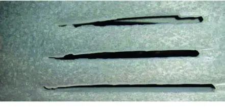
لوح polalloy مشقوق & خلفي
ألواح الحاجز المشقوقة والخلفية. تحدد بيانات المصنع المنشورة سماكة 50 mm وصلادة 58 HRC مع تكييف شكل الشقوق للخدمة. خطط للاستبدال عند سماكة متبقية 8–10 mm.
قدم أبعاد الألواح المشقوقة والظروف →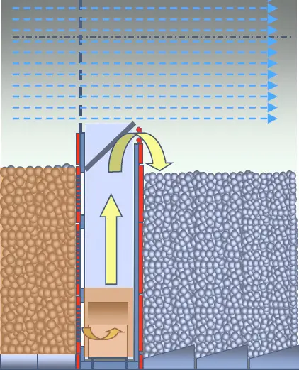
مغرفة رفع الحاجز & رأسها
تنقل المادة عبر الحاجز إلى الحجرة التالية وتنظم التدفق. طابق التصميم الثابت أو القابل للضبط والاتجاه والعدد والفتحة والوصلات وخلوص الوسائط مع رسومات diapol أو التركيب.
قدم سجلات المغرفة والحاجز →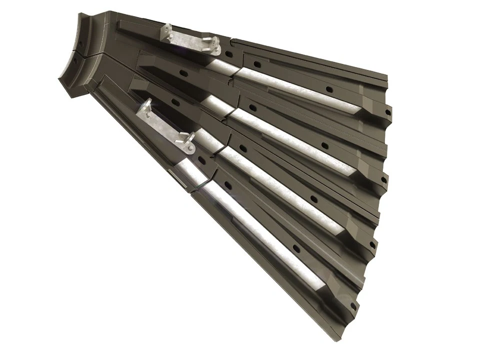
بطانة نهاية التغذية & الجدار الطرفي
تحمي الجدار الطرفي المستقيم عند المدخل ومخروط المدخل والغلاف المجاور. طابق المحيطات والثقوب والقطاعات والتراكبات وخلوص مزلق التغذية والموضع الأيسر أو الأيمن مع رسومات مجموعة النهاية.
عرض صفحة الجزء المشترك →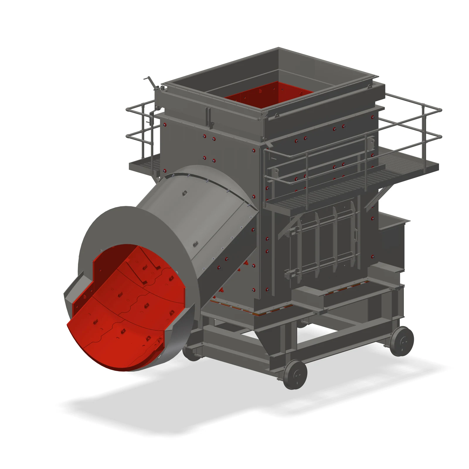
بطانة مزلق التغذية & التفريغ
تحمي المزلقات ونقاط السقوط والمنعطفات في تدفق المواد المغبرة. طابق التقوس والقطاعات والثقوب والتراكبات والتدفق وحيز الصيانة والخلوص مع نهاية المطحنة مع رسومات المزلق.
عرض صفحة الجزء المشترك →افحص قطع غيار الهيكل والإدارة فرديا بحسب نوع الدعم والقدرة ومواضع التوصيل والأحمال والمادة والمعالجة الحرارية وكشف العيوب والدقة والتزييت والمحاذاة.
غلاف مطحنة & شفة ربط
تحمل البطانات ووسائط الطحن والمادة وتنقل العزم. طابق القطر والطول والسماكة واللحامات والشفاه والثقوب والاستدارة والانحراف الدوراني ومراجع التركيب مع مخططات الترتيب العام.
عرض صفحة الجزء المشترك →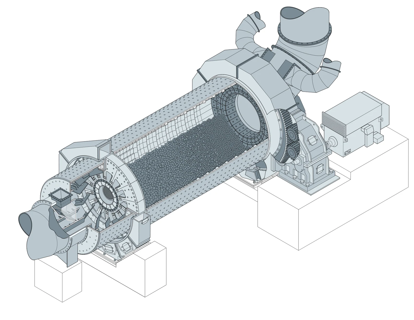
رأس مطحنة وجدار طرفي & مخروط مدخل
تصل الغلاف ومناطق التغذية والتفريغ والدعم. تستخدم التصاميم المرتكزة على الغلاف جدرانا طرفية مستقيمة ومخاريط مدخل قصيرة. طابق المحيطات والثقوب والشفاه واللحامات ومواضع اتصال الأختام الدوارة والثابتة مع رسومات التركيب.
عرض صفحة الجزء المشترك →حلقة انزلاق وحذاء انزلاق & مجموعة محامل
تنقل المطاحن المرتكزة على الغلاف الأحمال عبر حلقات انزلاق و2 أو 4 أو 6 أحذية في المجموعة. طابق قطر الحلقة وعرضها واستدارتها وعدد الأحذية وخلوص الزيت والحمل والمحاذاة الساخنة مع رسومات مجموعة المحامل.
فتح صفحة المحامل والجلب المشتركة →أسطوانة رفع هيدروليكية لحذاء المحمل
تقع تحت الأحذية لرفع الغلاف وتحديد موضعه وتوفير دعم متحكم فيه أثناء استبدال حذاء منفرد. طابق قطر التجويف والشوط والضغط ومسافة التركيب والتزامن وقفل الأمان مع الرسومات الهيدروليكية.
قدم سجلات نظام الرفع الهيدروليكي →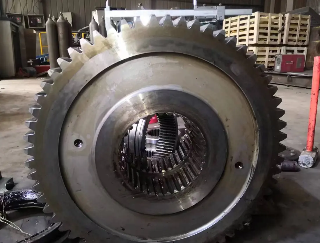
ترس حلقي وترس صغير & إدارة مباشرة
تنقل المطاحن الأقل قدرة العزم عبر ترس حلقي وترس صغير. افحصهما كزوج من حيث الموديول وعدد الأسنان وزاوية الضغط وعرض الوجه والميل والقطاعات والمسافة بين المحاور والمحامل والوصلات ونمط التلامس.
فتح صفحة التروس والتروس الصغيرة المشتركة →وحدة تروس COMBIFLEX® & عمود عائم
للمطاحن عالية القدرة، مع حد أقصى منشور قدره 8,000 kW للإدارة الواحدة و16,000 kW للإدارة المزدوجة. طابق أعمدة الدخول والخروج والأعمدة العائمة والتروس المقساة والوصلات والتزييت مع اللوحة ومخطط الترتيب العام.
فتح صفحة الإدارة للخدمة الشاقة المشتركة →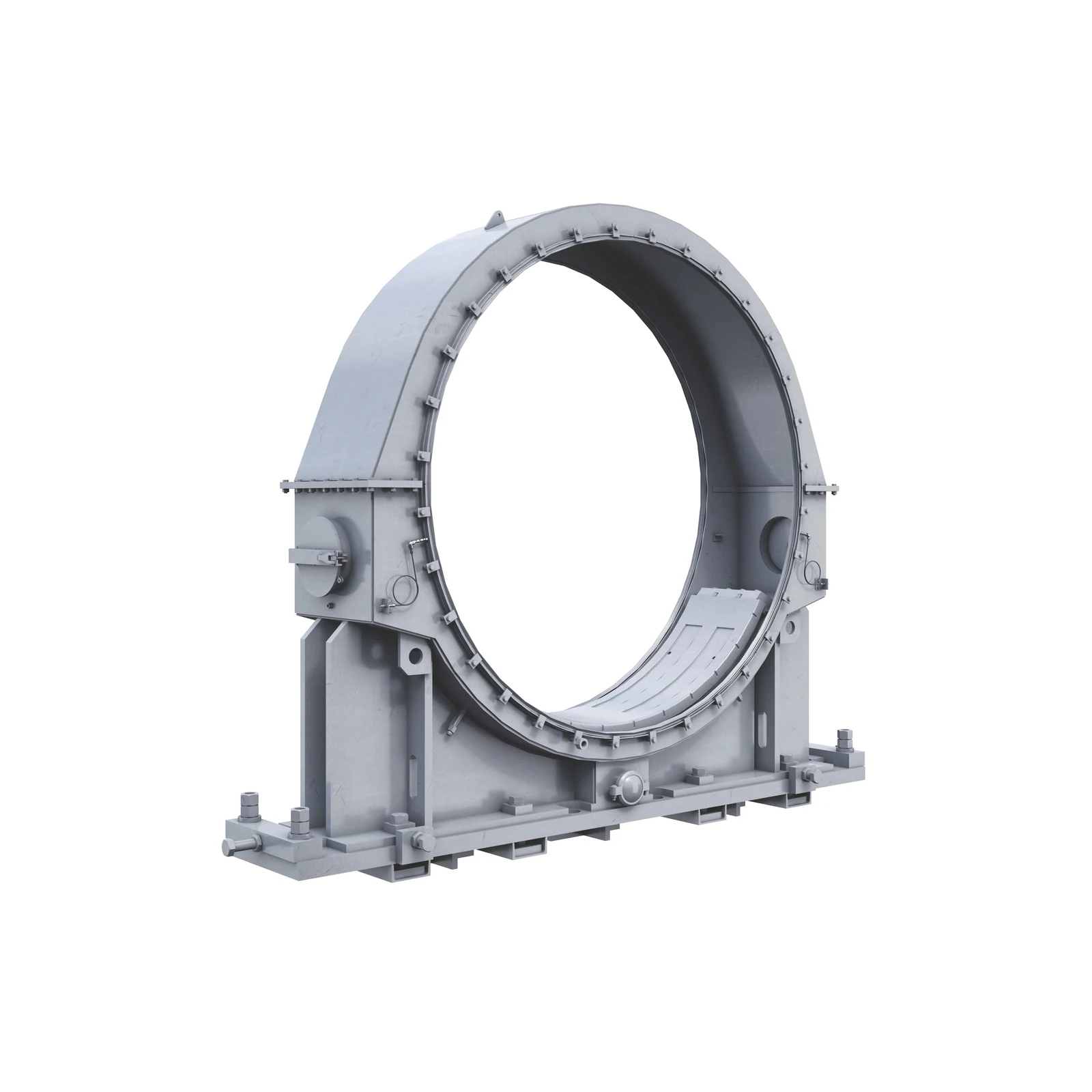
تزييت المحامل والأختام & قطع نظام الزيت
توفر أغشية هيدروستاتيكية وهيدروديناميكية وترشيحا وتبريدا وإحكاما لأحذية الانزلاق أو محامل المحاور الطرفية. طابق المضخات والصمامات والخطوط والفوهات والأختام والضغط والتدفق والحرارة والتشابكات مع مخططات التزييت.
فتح صفحة المحامل والجلب المشتركة →يجهز الموقع الحالي والكتيب المطاحن بحسب المشروع والمادة والحجرات والدعم والإدارة دون جدول موحد للطرازات والأحجام. يتطلب التصنيع اللوحة والرقم التسلسلي ومخطط الترتيب العام ورسومات القطع.
ليس تلقائيا. تركز الحجرة الأولى على صدم الكرات الكبيرة ورفعها والثانية على الطحن الناعم والتصنيف، بينما تضبط الحواجز الشقوق والتدفق وهبوط الضغط. طابق المقاطع والمواد والتثبيت منفصلة.
لا. افحص معا الترس المقابل والموديول وعدد الأسنان وزاوية الضغط والميل والمسافة بين المحاور والقطاعات والمحامل والوصلات والتزييت والمحاذاة والمادة والمعالجة الحرارية.
قدم اللوحة والرقم التسلسلي وأبعاد الغلاف والحجرات والدعامات وقدرة الإدارة والرسم وتوزيع البطانات والحواجز وصور القطع المستعملة والمادة والظروف للتحديد وتقييم المادة والتصنيع ومراقبة الجودة والتسليم.
أو تواصل معنا مباشرة: +86 156 3797 3199
zzx@anranst.com
تقدّم ANRANST لعملائها حول العالم التقييم الهندسي والإنتاج في مسابك معتمدة وفق المتطلبات الفنية للعميل ومراقبة الجودة وتسليم القطع الجاهزة لقطع التآكل المخصّصة وقطع الغيار الصناعية، مع إمكانية دعم قطع صناعية مخصّصة أخرى.
نراجع أسطح التزاوج وأبعاد الوصلات، ونقيّم إمكانية التصنيع من حيث المادة والمعالجة الحرارية.
Material grades and heat-treatment processes are specified order by order, stated in the technical agreement and tracked through production.
تأكيد الرسم، ومراقبة المواد والعمليات، ومتابعة الإنتاج، والفحص، وتنسيق القبول.
ننسّق التصنيع وتأكيد الجودة والتغليف والتسليم للقطع الكاملة ضمن سلسلة توريد متكاملة وعملية.
Provide the equipment brand, complete model and serial number, part name, part number or drawing number, drawing revision, quantity, material requirements and duty. If identifiers are unavailable, send photographs and key dimensions.
أرسل استفساراً