thyssenkrupp Polysius الأفران الدوارة

polro® two-support kilns, three-support kilns and polguide® drives: parts and repairs for tyres, rollers, thrust systems, gearing and seals.

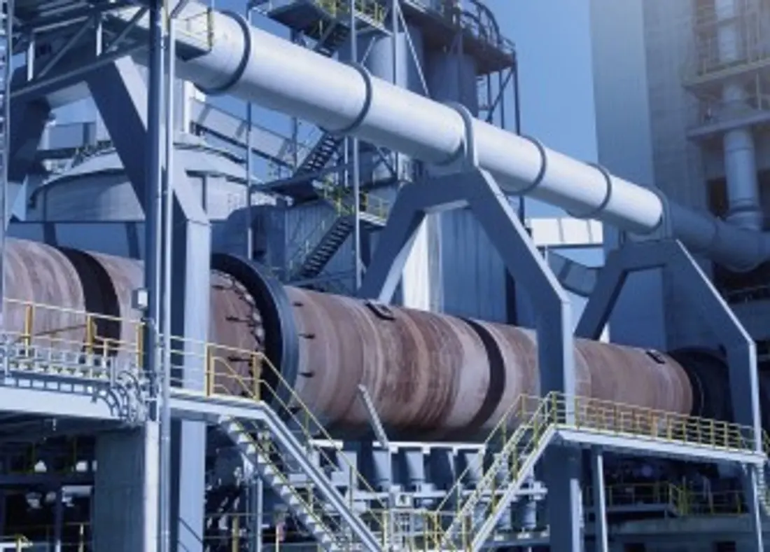
OEM photograph of a current Polysius polro® two-support kiln installation.
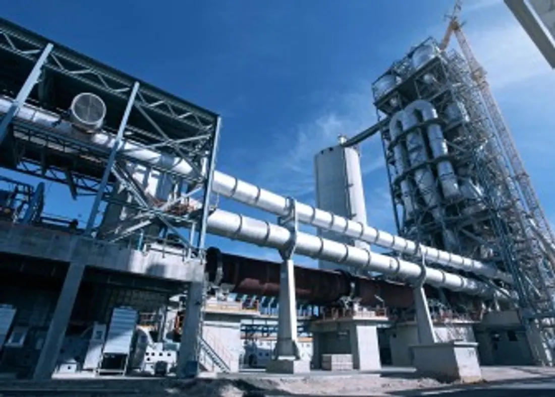
OEM photograph of a current Polysius three-support kiln installation.
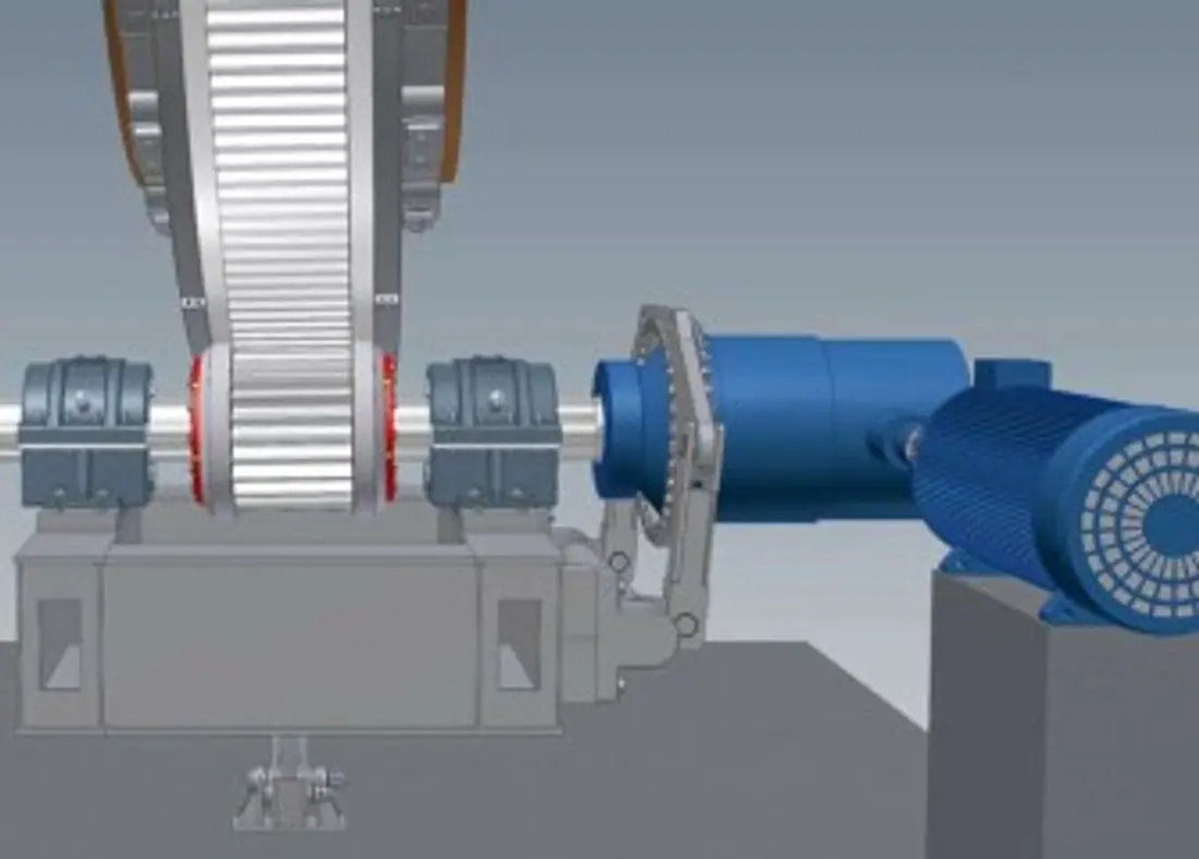
OEM diagram of the polguide® girth gear and pinion drive for identifying gear, shaft and guide interfaces.
OEM المعدات Reference

Identify the kiln before selecting tyres, rollers, drives, seals and repair supplies

Current Polysius kilns include polro® two-support and three-support configurations, with polguide® gearing available. ANRANST coordinates Chinese manufacture, quality control and finished-part delivery from the nameplate, serial number, kiln dimensions, support and drive arrangements, installed drawings and worn parts.

2 / 3 Current two- and three-support configurations
13–15 Published length-to-diameter ratio for modern precalciner kilns
>15 Length-to-diameter threshold for the OEM's three-support recommendation
±15 mm Published hydraulic axial travel range
Standard Models and Key Dimensions

Published Polysius kiln configurations and principal ranges

Current OEM products and documented historical installations help identify supports, drives, tyres, seals and thrust systems.

Published kiln / systemStructure and driveMain dimensions / parametersKey interfacesProduct status
polro® two-support rotary kilnTwo roller stations; direct friction drive through inlet-end rollersPublished length-to-diameter ratio for modern precalciner kilns: 13–15Splined tyres, self-aligning rollers, pneumatic end seals and hydraulic axial thrustCurrent product
Three-support rotary kilnThree roller stations; electromechanical planetary driveFor kiln length-to-diameter ratios greater than 15Splined or floating tyres, pneumatic end seals and hydraulic axial thrustCurrent product
polguide® girth gear and pinion driveSelf-aligning pinion shaft and guide rings maintain flank and tip clearancesFor kilns with different numbers of supportsCheck gearing, bearings, couplings, base, lubrication and alignment togetherCurrent product
Splined tyre systemA splined connection transfers load between shell and tyreConfirm installed dimensions of the tyre, shell, pads and roller stationCheck tyres, rollers, thrust and hot axial movement as a systemCurrent product
Floating / loose tyre systemPads, shims, axial stops and retaining rings transfer shell loads to the tyreConfirm installation gaps and hot ovality from drawings and measurementsCheck tyres, pads, stops, retaining rings and weldments togetherCurrent retrofit and spares offering
Published POLRO® installation referenceOEM brochure: two-support direct-drive designPublished reference capacity: 4,900 t/dللتحديد التاريخي فقط؛ أكِّد الأجزاء بواسطة اللوحة الاسمية والرقم التسلسلي والرسوماتHistorical published reference
Published three-support installation referenceOEM brochure: three-support gear-drive designPublished reference capacity: 5,000 t/dللتحديد التاريخي فقط؛ أكِّد الأجزاء بواسطة اللوحة الاسمية والرقم التسلسلي والرسوماتHistorical published reference

Before quotation or manufacture, confirm the complete nameplate, serial number, shell diameter and length, support count, tyre and roller dimensions, drive type, gear data, seals, drawing numbers and revisions.

قطع الغيار المستهلكة

Wear zones: lining, tyres and rollers, thrust, seals and pads

High-temperature corrosion, abrasion, contact fatigue, fretting and axial loads require different materials and processes. Confirm each installed position separately.

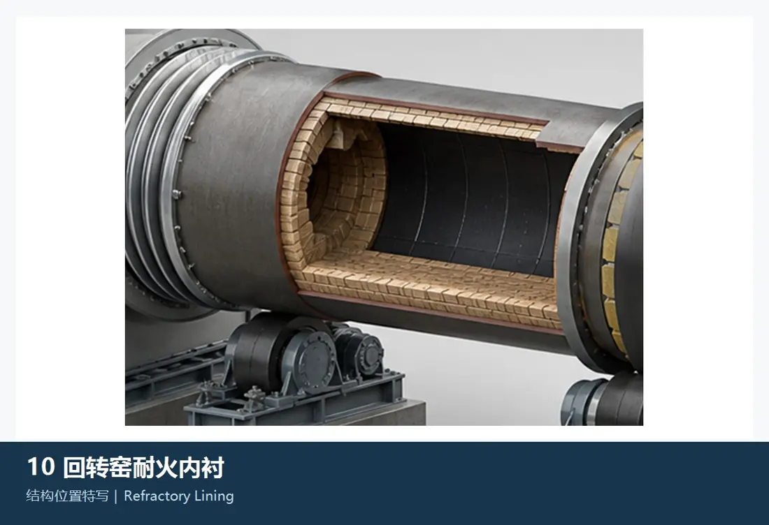
Refractory and burning-zone lining
01

Refractory and burning-zone lining

Refractory Lining & Burning-Zone Lining

Lining protects the shell and establishes burning conditions. Inlet, transition, burning and cooling zones differ in temperature, chemical attack, coating and mechanical loads; confirm zoning, thickness, brick shapes and anchors from lining drawings.

Material selection: Select refractories for temperature, clinker minerals, alkali–sulfur–chlorine circulation, thermal shock and existing lining life; one grade cannot serve the entire kiln.

View the common part page →
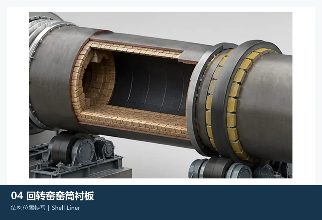
Inlet, outlet and transition protective liners
02

Inlet, outlet and transition protective liners

Kiln Inlet, Outlet & Transition Wear Liner

These protect metal areas at feed and discharge points, the inlet smoke chamber and kiln outlet. Confirm shape, segmentation, holes, overlaps, expansion gaps and refractory interfaces from installed drawings.

Material selection: Heat, abrasion, thermal cycles and local impacts act together. Assess heat- and wear-resistant alloys or composites against actual temperatures and failed parts.

View the common part page →
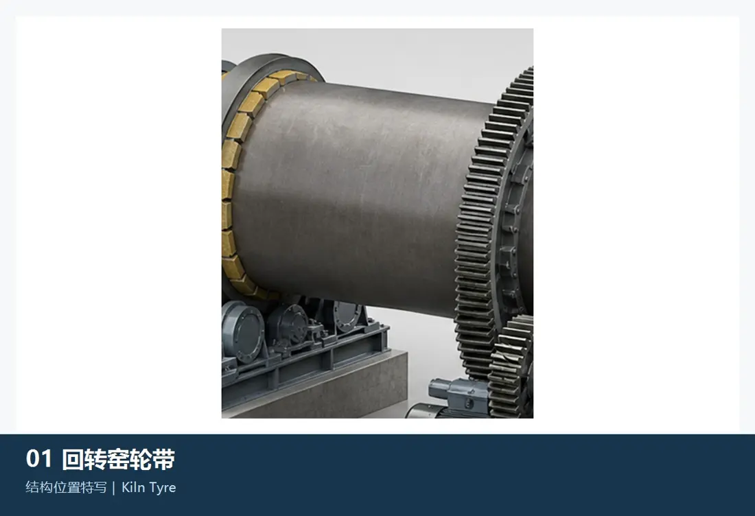
Kiln tyre running surface
03

Kiln tyre running surface

Kiln Tyre / Riding Ring Running Surface

Tyres transfer kiln loads to rollers. Inspect diameter, width, section, hot ovality, axial position, contact band, surface damage and load distribution together with the mating rollers.

Material selection: Large forged or cast-and-forged parts require core toughness, contact fatigue resistance, sound surfaces and dimensional stability. Check residual dimensions and load capacity before setting on-site grinding allowances.

View the common part page →
Support roller running surface
04

Support roller running surface

Supporting Roller Running Surface

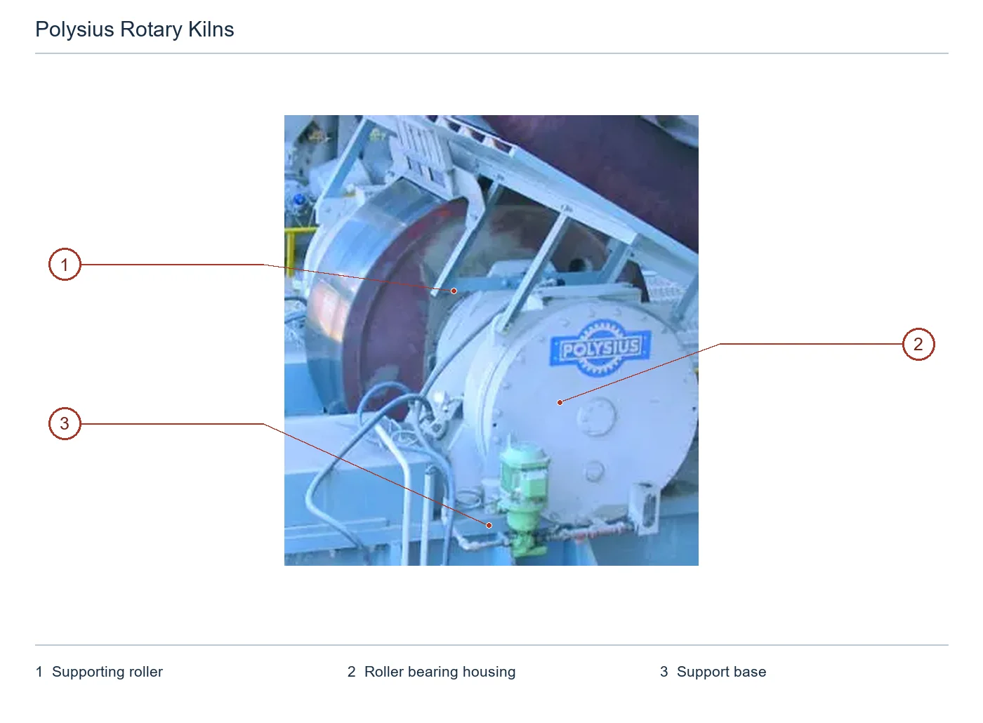
Each station supports a tyre on two roller units. Check roller and shaft diameters, width, contact band, spalling, taper, axes and base elevations as a tyre–roller contact pair.

Material selection: Current OEM literature specifies forged rollers. Manufacture or repair requires base-material, forging-quality, heat-treatment, machining, NDT and replacement-shaft fit checks.

View the common part page →
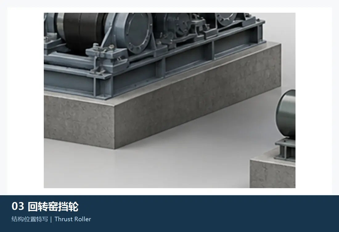
Thrust roller contact surface
05

Thrust roller contact surface

Thrust Roller Contact Surface

The thrust roller contacts the tyre side face to control axial position. Confirm roller and shaft diameters, tyre face, contact position, thrust direction, hydraulic stroke and hot axial travel from the thrust-system design.

Material selection: Contact fatigue, edge loads, lubrication and axial impacts determine life. Check the roller, shaft, bearings and tyre face together.

View the common part page →
Inlet / outlet graphite seal blocks
06

Inlet / outlet graphite seal blocks

Kiln Inlet / Outlet Graphite Seal Blocks

Graphite blocks surround the shell; tension ropes and counterweights maintain contact while allowing axial, radial and wobbling movement. Confirm shape, quantity, gaps, tensioning and air-cooled casing from the seal drawing.

Material selection: Blocks require heat resistance, self-lubrication, wear resistance and accommodation of shell runout. Graphite grade, density, segmentation and supports cannot be selected by appearance alone.

View the common part page →
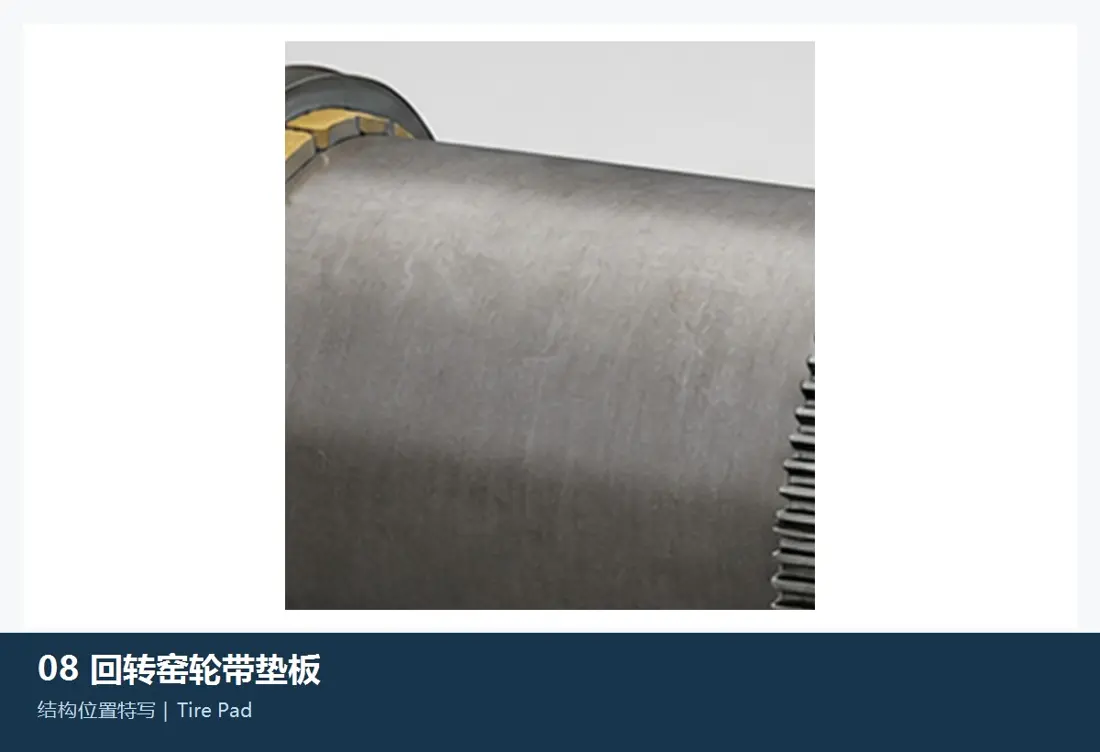
Tyre pads, shims and axial stops
07

Tyre pads, shims and axial stops

Tyre Pad, Shim & Axial Stop

These support floating tyres, set clearances and limit axial travel. Confirm curvature, thickness, quantity, weld positions, stop gaps and thermal expansion from installed drawings and measurements.

Material selection: Pads face contact compression, fretting, thermal cycling and welding effects. Balance material, hardness and weldability with shell protection.

View the common part page →
قطع الغيار

Support, tyre, gearing, hydraulic thrust and seal spares

Check drive and load-bearing spares as assemblies for installed interfaces, loads, materials, heat treatment, NDT, accuracy, lubrication and hot alignment.

Forged roller, shaft and base unit
01

Forged roller, shaft and base unit

Forged Supporting Roller, Axle & Base Unit

The roller and shaft form a permanently joined load-bearing unit; bearings on both sides and the base complete the station. Confirm diameters, width, bearing span, base datums, load and hot alignment before manufacture or repair.

Material selection: Check forging quality, material, heat treatment, NDT, fits, machining allowances and installation conditions separately for the roller, shaft, weld repair or replacement-shaft plan.

View the common part page →
Roller bearings, bushes and housings
02

Roller bearings, bushes and housings

Supporting Roller Bearing, Bush & Housing

Each roller unit has bearings on both sides and a base. Confirm journals, bush bores, oil gaps, bearing area, housing centre height, oil supply and cooling connections from drawings and measurements.

Material selection: Bearing alloy, steel backing, cast bond, scraping, oil film and journal surface determine reliability together. Replacement must account for the journal and lubrication system.

Open the shared bearing and bushing page →
Splined / floating tyre assembly
03

Splined / floating tyre assembly

Splined / Floating Kiln Tyre Assembly

The assembly includes the tyre and splined connection, or pads, shims, stops and retaining rings. Confirm section, diameter, width, holes, clearances, axial location and hot ovality from the full drawing set.

Material selection: Tyres, connectors and pads carry different loads and need separate material, heat-treatment, NDT, dimensional and welding specifications.

View the common part page →
polguide® girth gear, pinion and shafts
04

polguide® girth gear, pinion and shafts

polguide® Girth Gear, ترس صغير & Shafting

The self-aligning pinion shaft can move longitudinally; guide rings maintain flank and tip clearances. Check the gears, shafts, bearings, couplings, base and lubrication together.

Material selection: Compatibility depends on module, tooth count, pressure angle, helix hand, face width, centre distance, tooth and core properties, accuracy and contact pattern.

Open the shared gear and pinion page →
Hydraulic axial thrust system
05

Hydraulic axial thrust system

Hydraulic Axial Thrust System

Located on the downhill side, hydraulic thrust controls kiln axial position. OEM literature gives periodic travel of ±15 mm and short-stroke or combined short- and long-stroke configurations.

Material selection: Confirm the thrust roller, shaft, bearings, cylinder, sensors, valve block and seals together for load, stroke, pressure, position feedback and safety interlocks.

View the common part page →
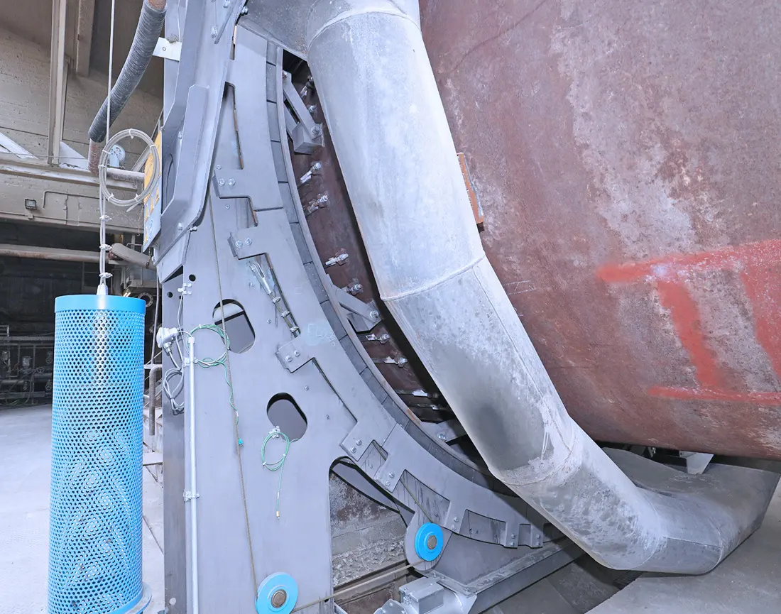
Pneumatic / graphite inlet and outlet seal assembly
06

Pneumatic / graphite inlet and outlet seal assembly

Pneumatic / Graphite Kiln Seal Assembly

Seal blocks or leaves, support rings, tensioners, counterweights, air-cooled casing and connectors compensate for axial, radial and wobbling kiln movement.

Material selection: Confirm seal materials, steelwork, fasteners and air cooling for temperature, negative pressure, dust, shell runout and maintenance access.

View the common part page →
Drive gearbox, coupling and lubrication components
07

Drive gearbox, coupling and lubrication components

Drive Gear Unit, Coupling & Lubrication Components

The three-support kiln's electromechanical planetary drive and polguide® gearing require gearboxes, couplings, bearings, brakes, lubrication and monitoring. Confirm nameplate, ratio, torque, shaft ends, base and interlocks from drive drawings.

Material selection: Specify gears, shafts, couplings, bearings and seals separately for load spectrum, accuracy, heat treatment, dynamic balance, lubrication and temperature.

Open the shared heavy-duty drive page →
Special Tooling

OEM-documented on-site kiln grinding and inspection equipment

Only the polgrind® mobile grinding and measuring system explicitly documented by Polysius for kiln tyres, rollers and slip rings is shown here.

polgrind® mobile tyre and roller grinding equipment
01

polgrind® mobile tyre and roller grinding equipment

polgrind® Mobile Kiln Tyre & Roller Grinding Tool

The OEM's mobile belt-grinding system repairs tyres, rollers and slip rings on site, correcting out-of-roundness, waviness, taper and damaged surfaces while reducing large-component removal.

Material selection: This dedicated kiln machining equipment requires mounting datums, permissible stock removal, belts, drive, guarding and travel paths matched to dimensions and damage.

Submit tyre or roller dimensions and damage details →
Tyre / roller roundness measurement and site records
02

Tyre / roller roundness measurement and site records

Kiln Tyre / Roller Roundness Measurement & Documentation

Record diameter, roundness and surface condition before and after grinding to establish machining datums, control stock removal and document repair acceptance.

Material selection: Define measurement points, datums, limits, hot or cold conditions and report format for the specific kiln. Generic gauge readings do not replace an installed-equipment assessment.

Submit site inspection and repair scope →

Why is a similar diameter insufficient for replacing kiln parts?

Tyres, rollers, thrust parts, gears and seals depend on support count, loads, hot ovality, axial travel, centre distances and interfaces. Check nameplate, serial number, assembly and part drawings, and measurements.

Can only the tyre or roller be repaired?

First measure both parts for diameter, roundness, taper, contact band and axes. With systematic uneven loading, repairing one part may leave waviness, edge loading or axial wandering unresolved.

Can you coordinate on-site kiln inspection and finished-part delivery?

Yes. ANRANST can coordinate consultation, manufacturer sourcing, material and drawing checks, quality control, on-site inspection and finished-part delivery within the project scope.

Submit kiln nameplate, tyre and roller dimensions, drawings or worn-part records

Provide shell diameter and length, support count, drive type, tyre and roller dimensions, axial movement, drawing numbers, worn-part photos, materials and failure details. We coordinate identification, material assessment, manufacture, quality control and delivery.

Submit التفاصيل for a Quote

رقم الهاتف: +86 156 3797 3199
zzx@anranst.com

خدمات صنع في الصين

من التقييم الفني إلى تسليم المنتج بالكامل

توفر شركة ANRANST للعملاء العالميين تقييمات هندسية، واختيار التصنيع الصيني، ومراقبة الجودة، وتسليم الأجزاء النهائية لقطع الغيار الصناعية المقاومة للتآكل حسب الطلب، ويمكنها أيضًا دعم قطع الغيار الصناعية الأخرى حسب الطلب.

01

مراجعة الرسومات والهندسة

قم بمراجعة أسطح التزاوج وأبعاد الواجهة، وقم بتقييم جدوى المواد والمعالجة الحرارية والتصنيع.

02

تحديد المادة والمعالجة الحرارية

تُحدَّد درجات المواد وعمليات المعالجة الحرارية لكل طلب على حدة، وتُثبَّت في الاتفاقية الفنية وتُتابَع أثناء الإنتاج.

03

ضبط الجودة

يشمل ذلك تأكيد الرسم، ومراقبة المواد والعمليات، وتتبع الإنتاج، وتنسيق عمليات الفحص والقبول.

04

تسليم المنتج النهائي

تنظيم عمليات التصنيع والتحقق من الجودة والتعبئة والتغليف وتسليم المنتجات النهائية الكاملة لتشكيل حلقة إمداد قابلة للتنفيذ.

قم بتزويدنا بالنماذج الحالية، والرسومات، وأرقام الرسومات، وأرقام الأجزاء، والمواد، أو معلومات ظروف التشغيل، وسنقوم بتحديد التحقق الفني ومسار التوريد وفقًا لذلك.

إرسال طلب