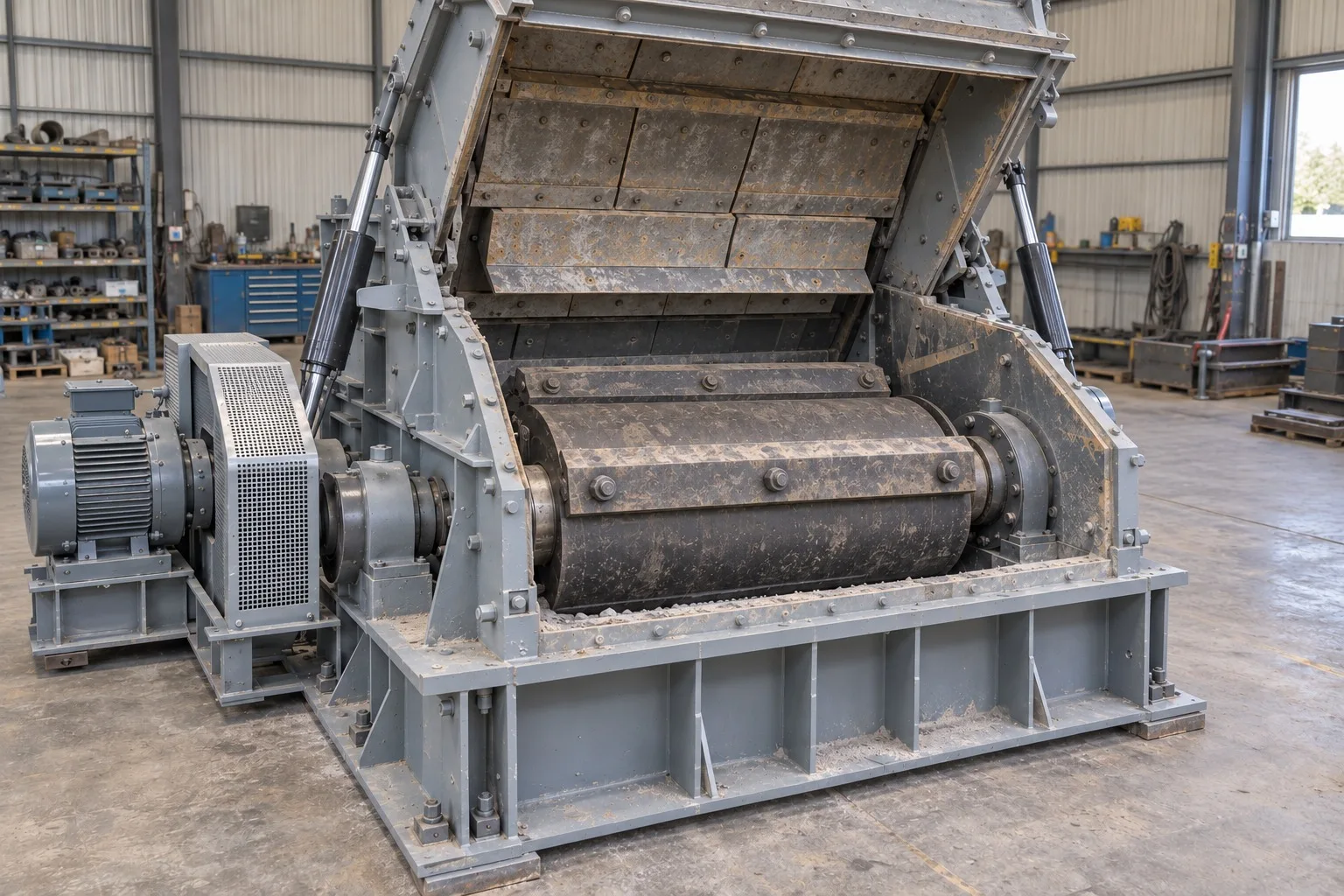
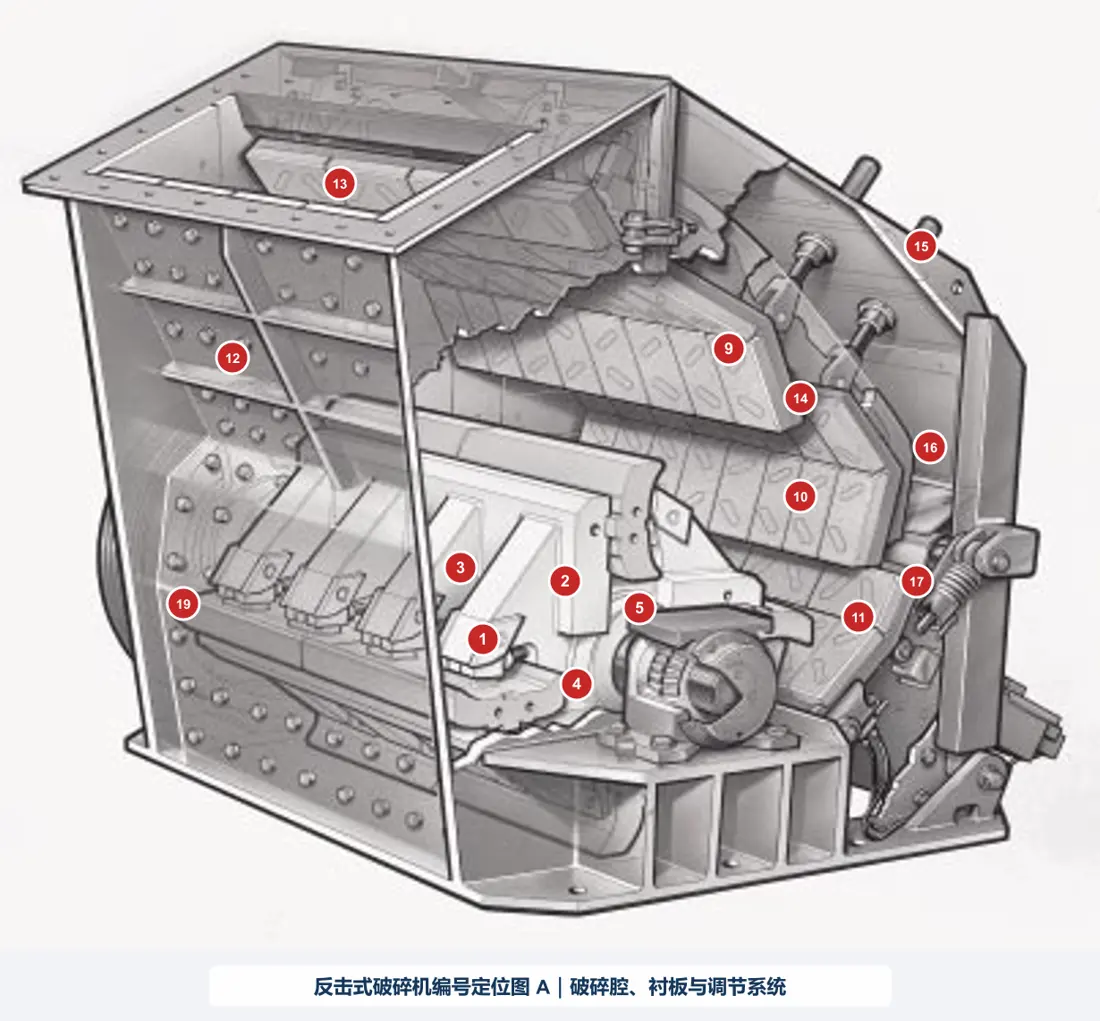
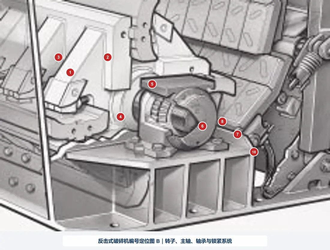
In an impact crusher, blow bars on a high-speed rotor strike the feed. Material then impacts the first, second and optional third apron liners, as well as other particles. Wear is concentrated in four main systems:
Equipment Parts
Part Identification and Technical Details
Explore part names, images, material options and technical requirements. Select a card to open the corresponding replacement part page.
Individual parts
Individual and Maintenance Parts
01
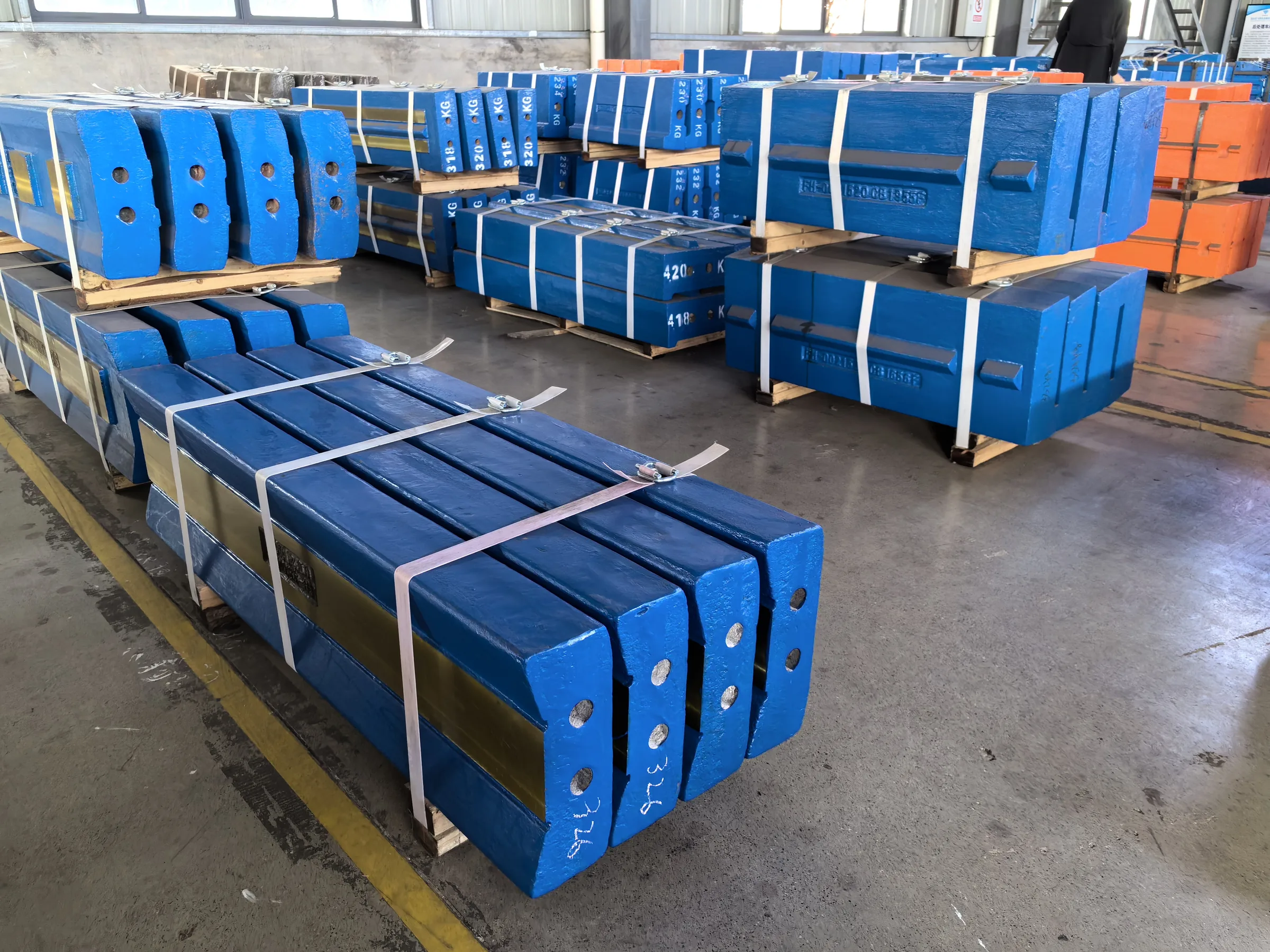
Blow Bar
- Installation position
- In the blow-bar pockets around the rotor rim; working face toward the feed; retained by wedges/fasteners. Distinct from apron liners and backing bars.
- Candidate material families
- High-manganese steel / martensitic steel / high-chromium white iron / ceramic or MMC composites (select by impact–abrasion–tramp mix; not a single guaranteed grade)
- Function
- Strikes feed at high speed and throws it into the apron zone; a principal consumable for HSI wear cost.
02
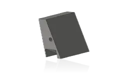
Blow Bar Retaining Wedge
- Installation Position
- Locking slot behind the side of the blow bar
- Material Options
- Quenched and tempered 42CrMo / 4140 alloy steel or OEM-specified high-strength cast steel
- Function
- Clamps the blow bar and transfers centrifugal and impact loads
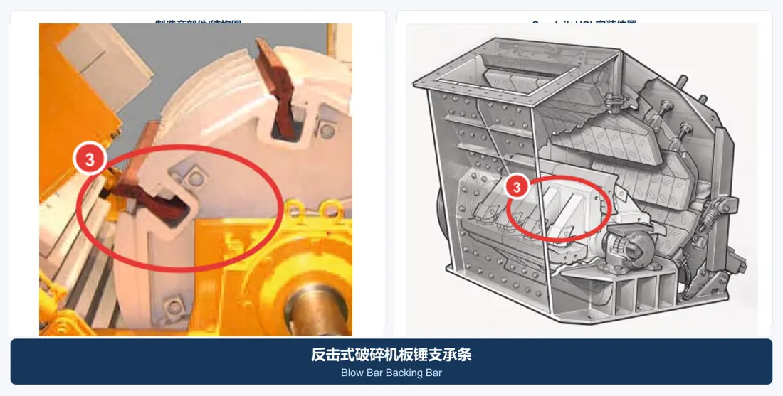
03
Blow Bar Backing Bar
- Installation Position
- Between the back of the blow bar and the rotor seat
- Material Options
- Quenched and tempered alloy steel / high-strength cast steel
- Function
- Supports the blow bar and maintains the seating surfaces and assembly clearances
04
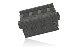
Rotor Assembly
- Installation Position
- High-speed rotating assembly in the center of the crushing chamber
- Material Options
- High-strength low-alloy cast steel, welded forged construction or welded structural steel
- Function
- Carries the blow bars and stores rotational energy
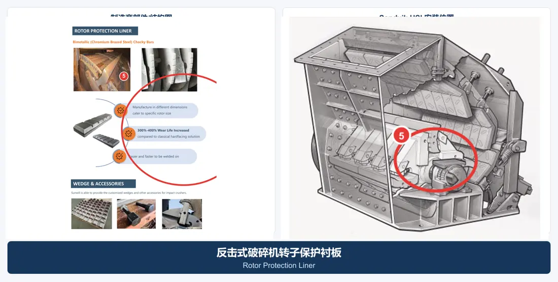
05
Rotor Protection Liner
- Installation Position
- Exposed surfaces of the rotor discs and blow bar seats
- Material Options
- Martensitic steel / high-chromium bimetallic material / ceramic composite
- Function
- Protects the rotor body from fines and rebounding material
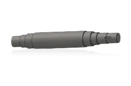
06
Rotor Shaft
- Installation Position
- Passes through the rotor and into the bearing housings on both sides
- Material Options
- Forged, quenched and tempered 42CrMo / 4140 / 34CrNiMo6 steel
- Function
- Transmits torque and carries bending, impact and fatigue loads
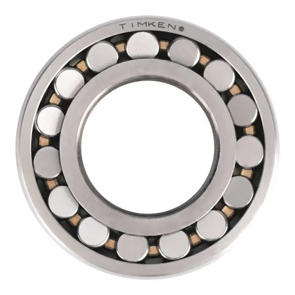
07
Rotor Bearing
- Installation Position
- Inside the bearing housings at both ends of the main shaft
- Material Options
- 100Cr6 / SAE 52100 bearing steel
- Function
- Supports the heavily loaded high-speed rotor and controls radial and axial movement
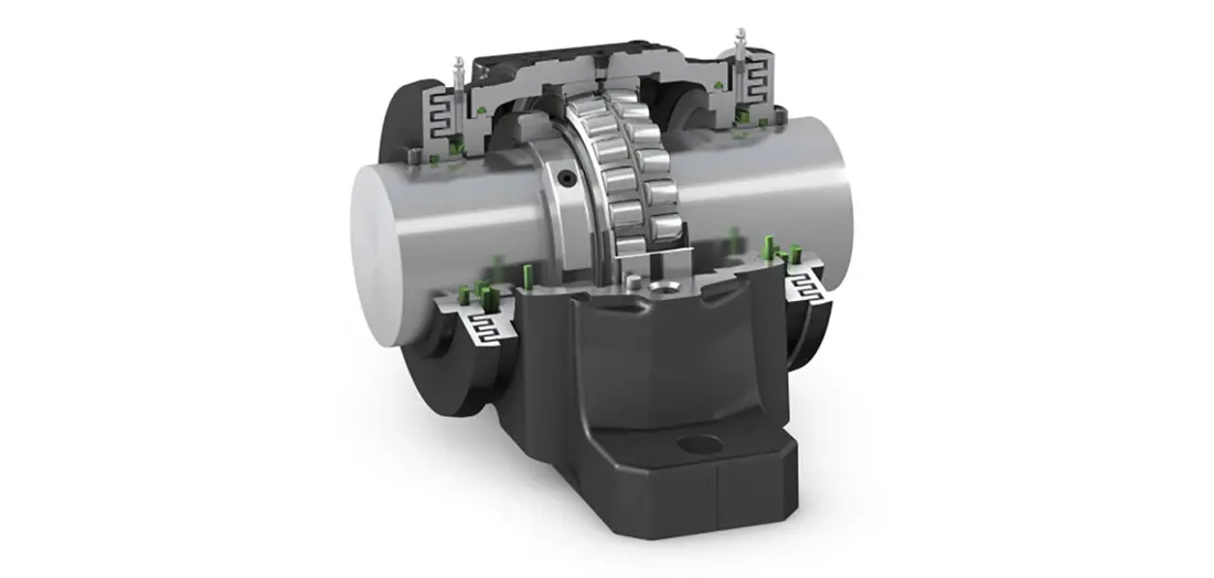
08
Rotor Bearing Seal
- Installation Position
- At the bearing housing and projecting main shaft
- Material Options
- Labyrinth / Taconite arrangement with NBR, HNBR, FKM or V-ring seals
- Function
- Excludes dust and water while retaining grease
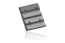
09
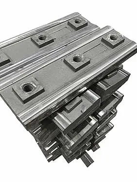
First Apron Liner
- Installation Position
- Working surface of the first impact apron on the feed side
- Material Options
- Manganese steel / martensitic steel / tough composite materials
- Function
- Handles the first rebound crushing stage with the largest particles and highest impact
10
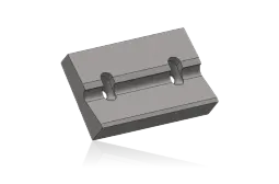
Second Apron Liner
- Installation Position
- Second working surface downstream of the first impact apron
- Material Options
- Martensitic steel / high-chromium white iron / ceramic composite
- Function
- Provides further crushing and controls particle shape and discharge size
11
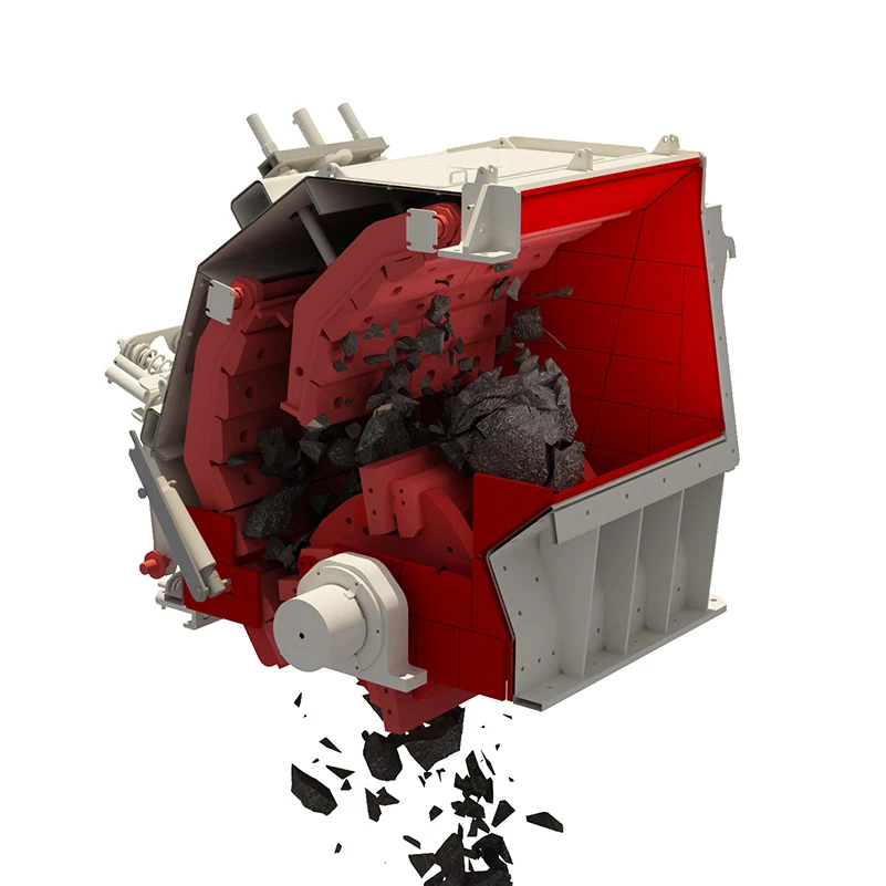
Third Apron Liner
- Installation Position
- Working surface of the optional third impact apron
- Material Options
- High-chromium white iron / martensitic steel / ceramic composite
- Function
- Provides further shaping and crushing of finer particles
12
Side Liner
- Installation Position
- Left and right sidewalls of the crushing chamber
- Material Options
- Manganese steel / martensitic steel / high-chromium or bimetallic material
- Function
- Protects the frame sidewalls from impact and abrasion
13
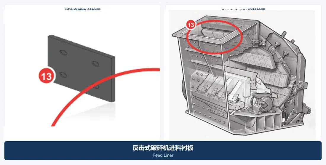
Feed Liner
- Installation Position
- Feed opening and upper feed guidance area
- Material Options
- Grade 400–500 wear plate / manganese steel / rubber-ceramic composite
- Function
- Absorbs feed impact and protects the inlet casing
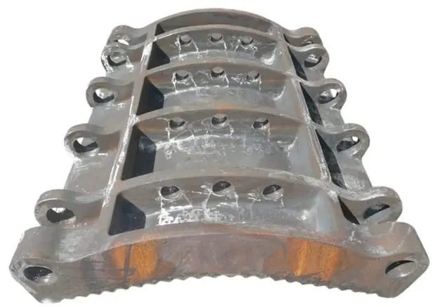
14
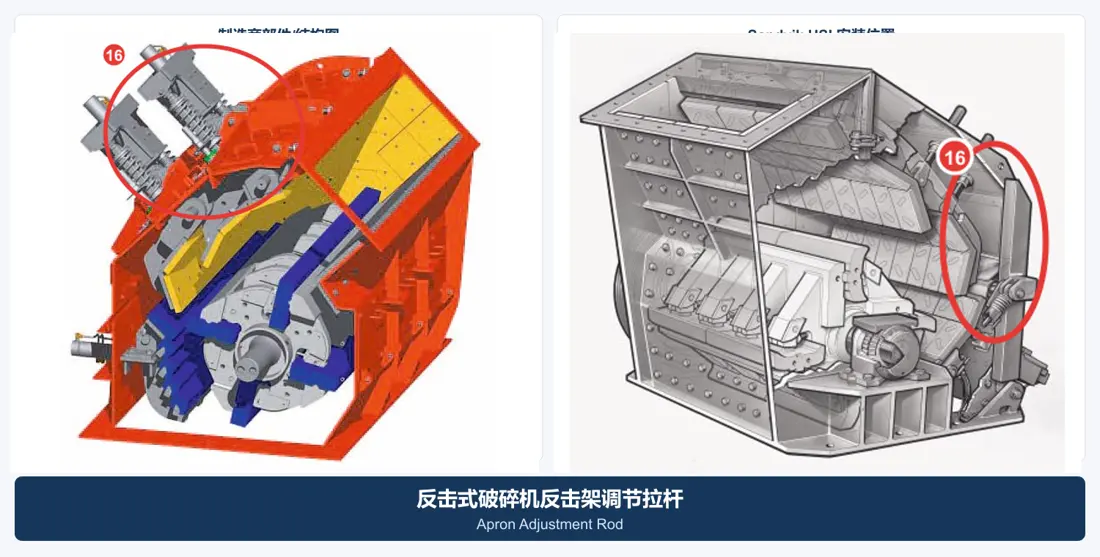
Impact Apron Assembly
- Installation Position
- Adjustable impact aprons above and behind the rotor
- Material Options
- High-strength cast steel or welded structural steel with replaceable working liners
- Function
- Supports the impact liners and provides an adjustable crushing gap
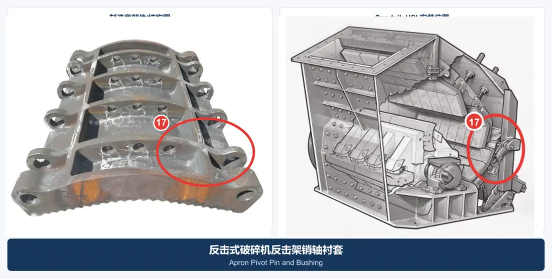
17
Apron Pivot Pin and Bushing
- Installation Position
- Impact apron pivots and adjustment linkage joints
- Material Options
- 42CrMo pins with copper-alloy or hardened steel bushings
- Function
- Provides pivot support under oscillation, impact and boundary lubrication
18
Bearing Housing
- Installation Position
- Outside the frame at both ends of the rotor shaft
- Material Options
- Ductile iron / cast steel / welded steel construction to the OEM design
- Function
- Locates bearings, seals and lubrication passages while maintaining alignment at both ends
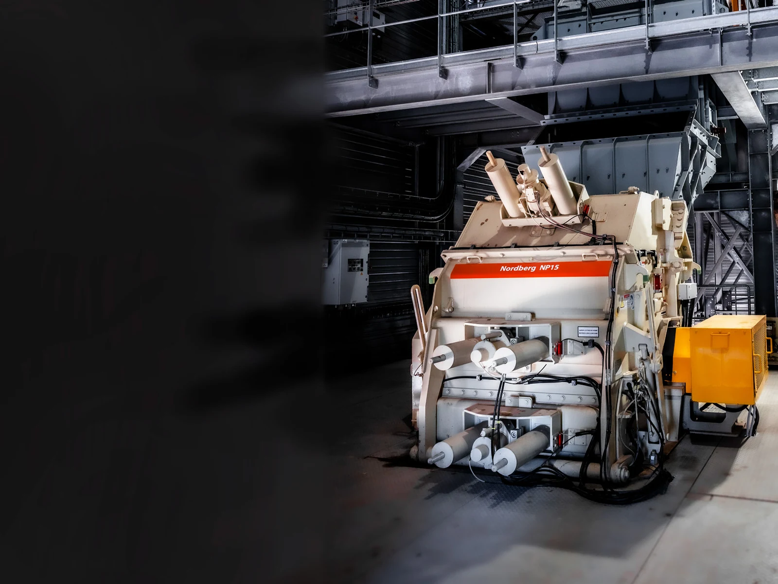
15
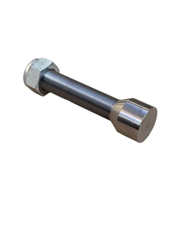
Apron Adjustment Cylinder
Materials for similarly named parts may differ by OEM, machine model and operating conditions. Confirm the machine model, drawing and measured dimensions before ordering or manufacture.
Material System
| Material Family | Typical Property Range | Recommended Operating Conditions | Main Limitations |
|---|
| Manganese Steel | Typical initial hardness of approximately 180–240 HB; relies on work hardening under impact | Large feed and high impact, with potential tramp material | May not work-harden sufficiently with low impact or fine feed |
| Martensitic Steel | Commonly around 45–55 HRC, balancing hardness with some toughness | Medium to high abrasion with moderate impact | Control heat treatment, hardness gradients in thick sections and residual stresses |
| High-Chromium White Cast Iron | Working layer commonly around 58–65 HRC | Low to moderate impact and high abrasion with relatively fine, consistent feed | Greater brittleness; unsuitable for heavy lump impact or frequent tramp metal |
| Ceramic / MMC Composites | Hard particles provide abrasion resistance while the steel or iron matrix carries the load | Stable, highly abrasive duties where longer wear life offers significant value | Validate insert placement, bonding quality, impact limits and recycling risks |
7. Procurement and Acceptance Checks
1. Provide the equipment OEM, model, serial number, rotor diameter and width, blow bar pocket dimensions, model details and used-part photos. 2. Weigh and match blow bars as a set. Metso NP replacement guidance permits a mass difference of up to 2% between opposed blow bars; follow the balancing specification for other brands. 3. Record composition, heat-treatment batch, hardness distribution, nondestructive test results and individual mass for bars, liners and wedges. 4. After rotor repair, check dimensions, weld NDT and static/dynamic balance; do not use hardfacing to conceal structural cracks. 5. Check shaft and housing concentricity, journal fits, tolerances, seal grooves and lubrication passages. 6. Specify the ceramic type, volume fraction or arrangement, matrix grade, bonding method, impact restrictions and site monitoring criteria for ceramic composites. 7. Clean and inspect wedges, support surfaces and locking parts during replacement. Worn wedges increase the risk of loose or broken blow bars.
Materials for similarly named parts may differ by OEM, machine model and operating conditions. Confirm the machine model, drawing and measured dimensions before ordering or manufacture.