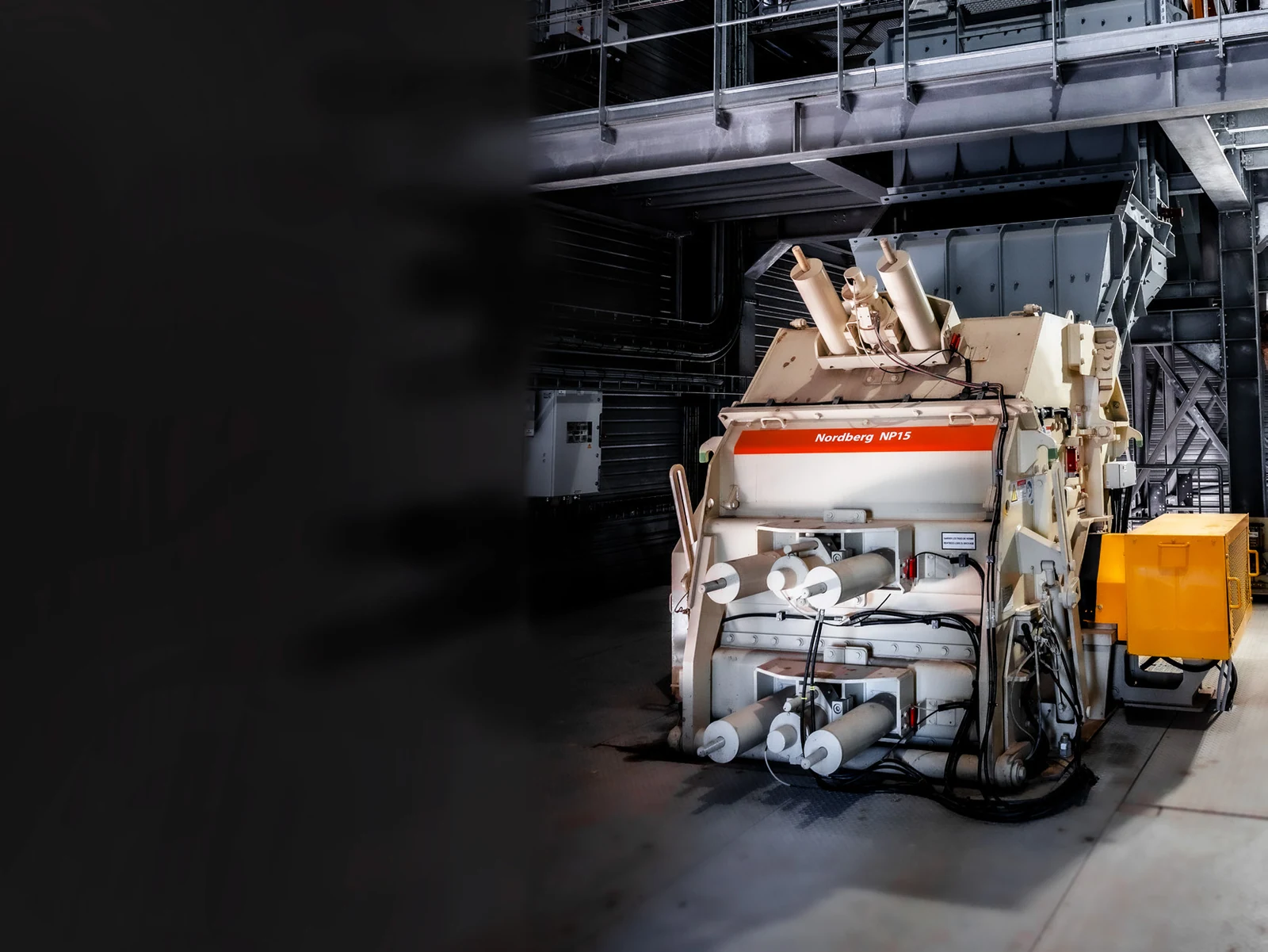
Concasseur à percussion

Utilisé pour le concassage secondaire et la mise en forme. Barres de frappe et blindages d'impact subissent une usure d'impact à haute vitesse ; fonte à haut chrome et composites céramiques selon l'abrasivité de l'alimentation.
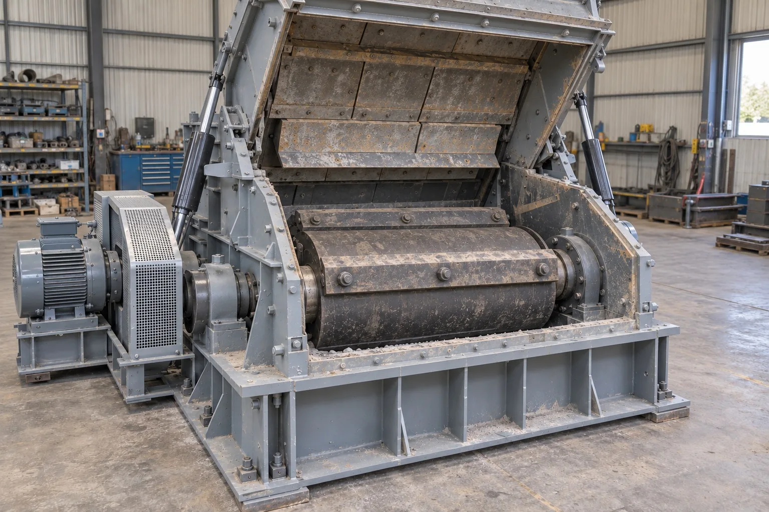
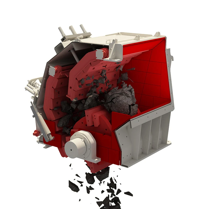
Concasseur à percussion

Dans un concasseur à percussion, les barres de frappe d'un rotor à haute vitesse frappent l'alimentation. Le matériau percute ensuite les premier, deuxième et éventuellement troisième blindages de tablier, ainsi que d'autres particules. L'usure se concentre dans quatre systèmes principaux.

Identification des pièces et détails techniques

Principaux : barres de frappe, coins/barres d'appui, blindages de tablier, blindages latéraux et protection de rotor ; texte au niveau famille/nom commercial.
Individual parts

Individual and Maintenance Parts

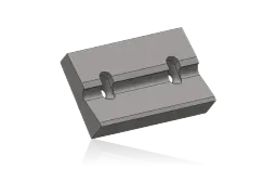
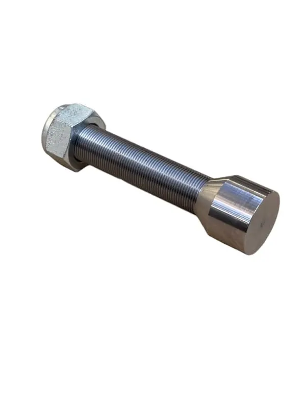
Blow Bar Locking Wedge
02

Blow Bar Locking Wedge

Blow Bar Retaining Wedge

Installation Position
Locking slot behind the side of the blow bar
Material Options
Quenched and tempered 42CrMo / 4140 alloy steel or OEM-specified high-strength cast steel
Function
Clamps the blow bar and transfers centrifugal and impact loads
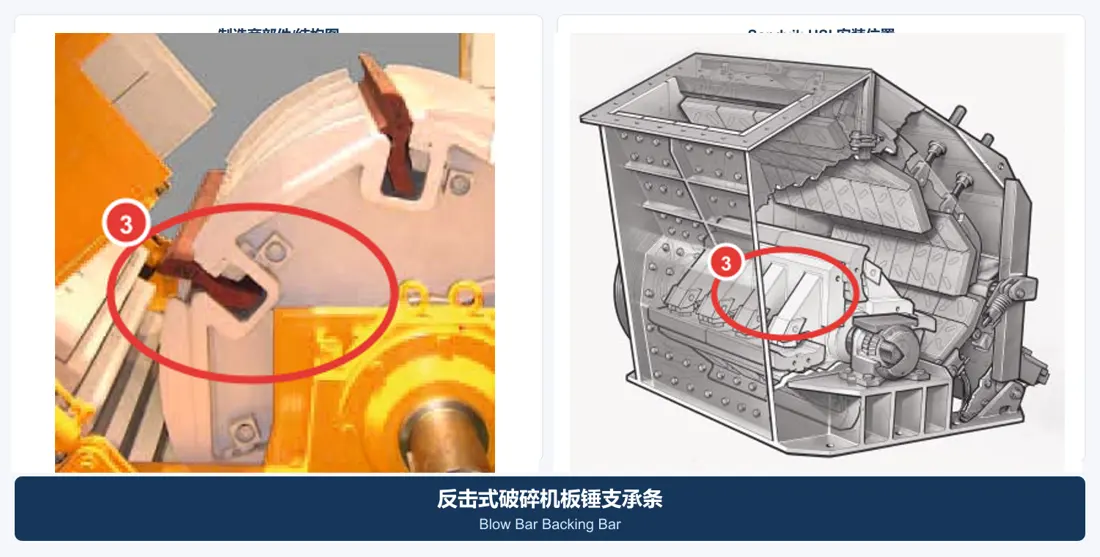
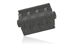
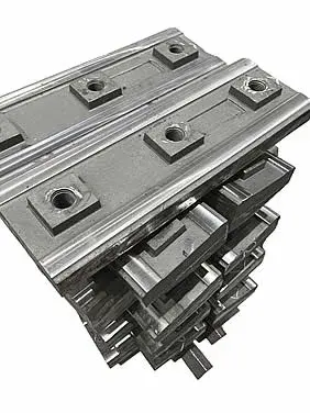
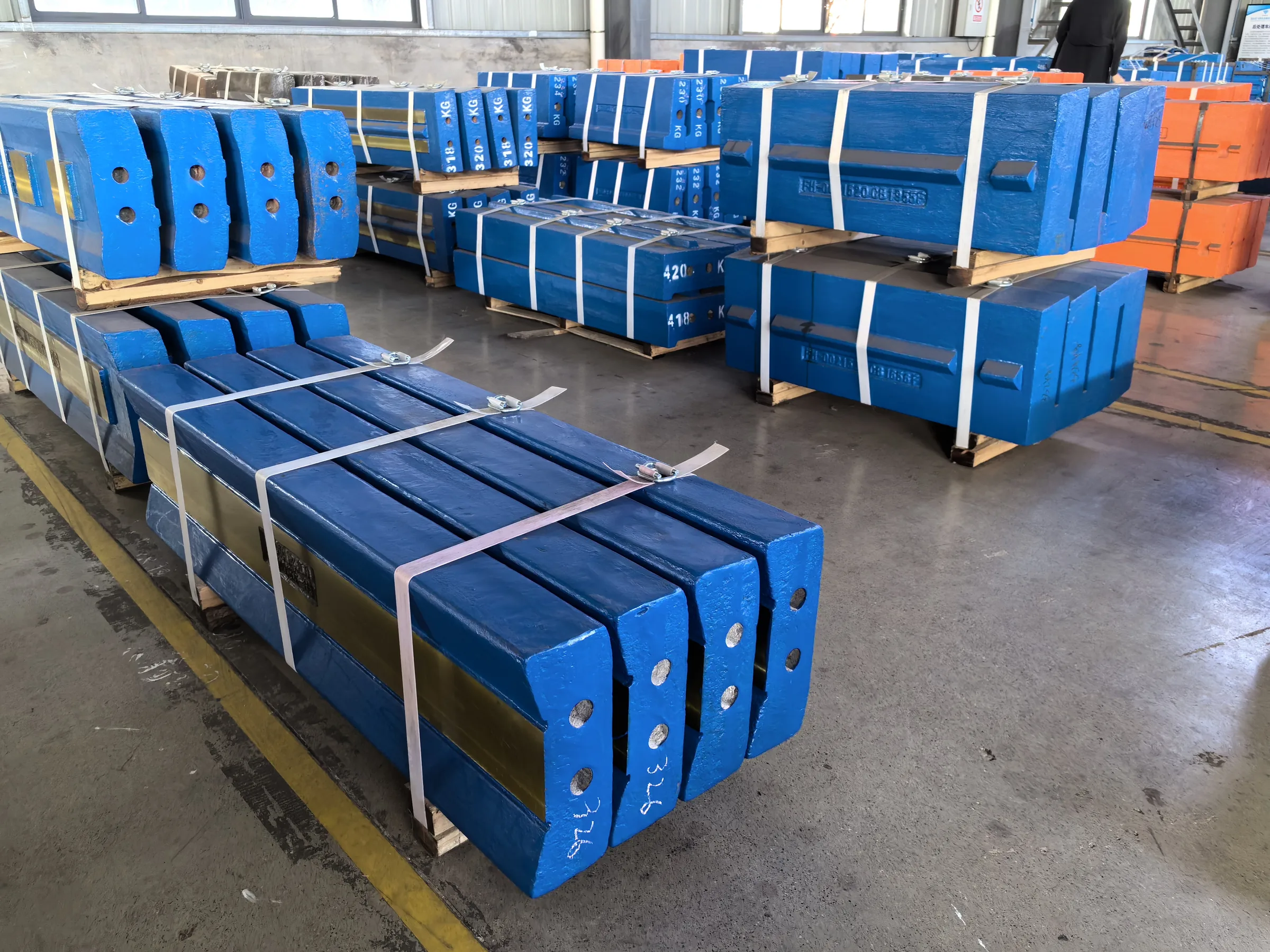
Blow Bar Support Strip
03

Blow Bar Support Strip

Blow Bar Backing Bar

Installation Position
Between the back of the blow bar and the rotor seat
Material Options
Quenched and tempered alloy steel / high-strength cast steel
Function
Supports the blow bar and maintains the seating surfaces and assembly clearances
Rotor Assemblies
04

Rotor Assemblies

Rotor Assembly

Installation Position
High-speed rotating assembly in the center of the crushing chamber
Material Options
High-strength low-alloy cast steel, welded forged construction or welded structural steel
Function
Carries the blow bars and stores rotational energy
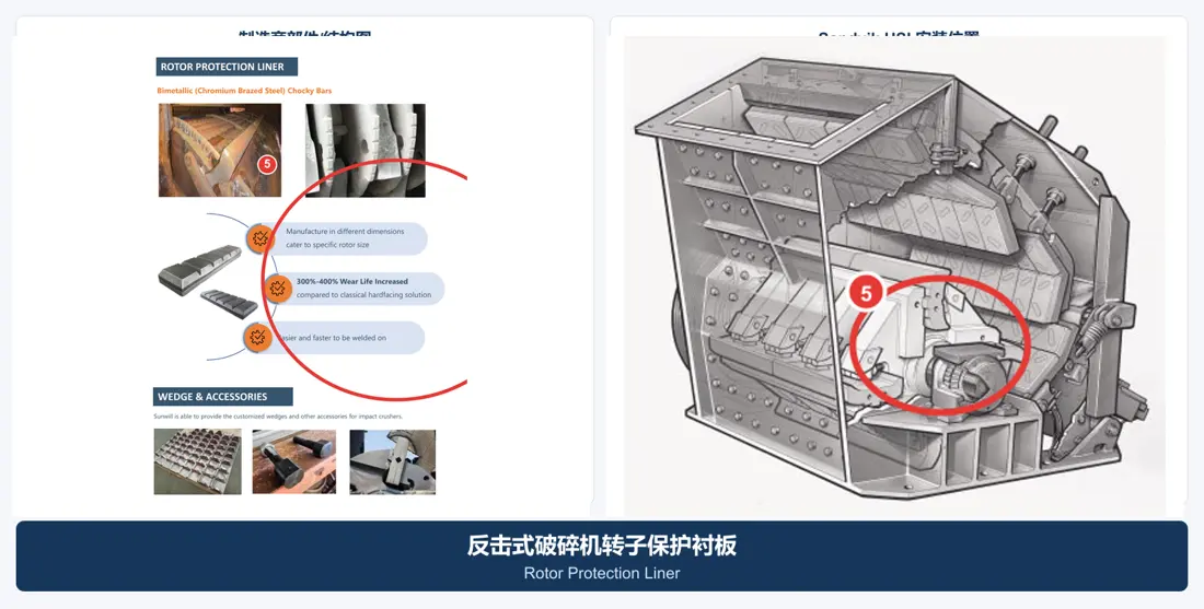
Rotor Protective Liner
05

Rotor Protective Liner

Rotor Protection Liner

Installation Position
Exposed surfaces of the rotor discs and blow bar seats
Material Options
Martensitic steel / high-chromium bimetallic material / ceramic composite
Function
Protects the rotor body from fines and rebounding material
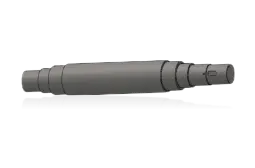
Rotor Main Shaft
06

Rotor Main Shaft

Rotor Shaft

Installation Position
Passes through the rotor and into the bearing housings on both sides
Material Options
Forged, quenched and tempered 42CrMo / 4140 / 34CrNiMo6 steel
Function
Transmits torque and carries bending, impact and fatigue loads
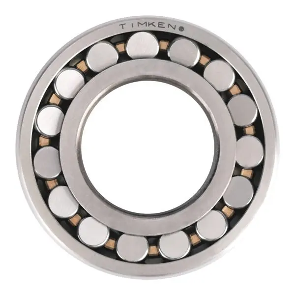
Rotor Bearing
07

Rotor Bearing

Rotor Bearing

Installation Position
Inside the bearing housings at both ends of the main shaft
Material Options
100Cr6 / SAE 52100 bearing steel
Function
Supports the heavily loaded high-speed rotor and controls radial and axial movement
Rotor Bearing Seal
08

Rotor Bearing Seal

Rotor Bearing Seal

Installation Position
At the bearing housing and projecting main shaft
Material Options
Labyrinth / Taconite arrangement with NBR, HNBR, FKM or V-ring seals
Function
Excludes dust and water while retaining grease
Primary Apron Liner
09

Primary Apron Liner

First Apron Liner

Installation Position
Working surface of the first impact apron on the feed side
Material Options
Manganese steel / martensitic steel / tough composite materials
Function
Handles the first rebound crushing stage with the largest particles and highest impact
Secondary Apron Liner
10

Secondary Apron Liner

Second Apron Liner

Installation Position
Second working surface downstream of the first impact apron
Material Options
Martensitic steel / high-chromium white iron / ceramic composite
Function
Provides further crushing and controls particle shape and discharge size
Third Apron Liners
11

Third Apron Liners

Third Apron Liner

Installation Position
Working surface of the optional third impact apron
Material Options
High-chromium white iron / martensitic steel / ceramic composite
Function
Provides further shaping and crushing of finer particles
Side Liners
12

Side Liners

Side Liner

Installation Position
Left and right sidewalls of the crushing chamber
Material Options
Manganese steel / martensitic steel / high-chromium or bimetallic material
Function
Protects the frame sidewalls from impact and abrasion
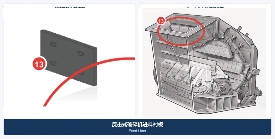
Feed Liners
13

Feed Liners

Feed Liner

Installation Position
Feed opening and upper feed guidance area
Material Options
Grade 400–500 wear plate / manganese steel / rubber-ceramic composite
Function
Absorbs feed impact and protects the inlet casing
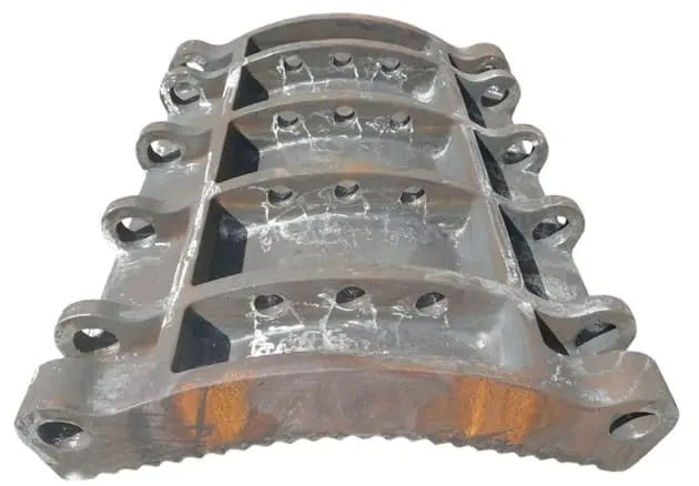
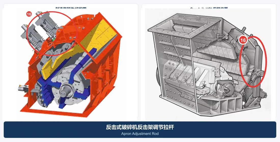
Impact Apron Assembly
14

Impact Apron Assembly

Impact Apron Assembly

Installation Position
Adjustable impact aprons above and behind the rotor
Material Options
High-strength cast steel or welded structural steel with replaceable working liners
Function
Supports the impact liners and provides an adjustable crushing gap
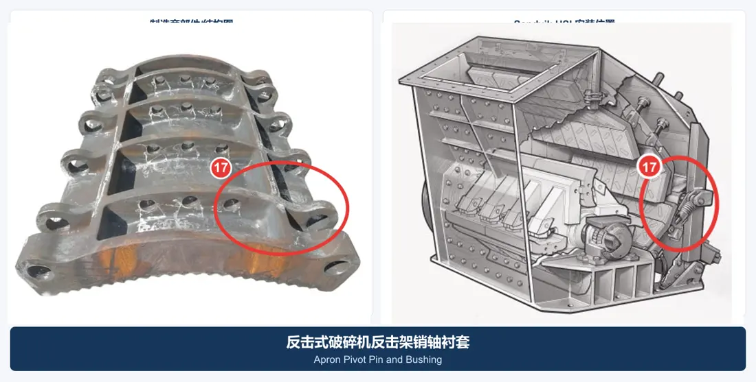
Apron Pivot Pin Bushing
17

Apron Pivot Pin Bushing

Apron Pivot Pin and Bushing

Installation Position
Impact apron pivots and adjustment linkage joints
Material Options
42CrMo pins with copper-alloy or hardened steel bushings
Function
Provides pivot support under oscillation, impact and boundary lubrication
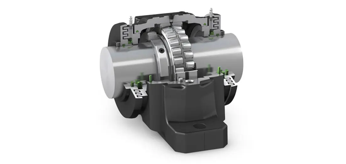
Bearing Housing
18

Bearing Housing

Bearing Housing

Installation Position
Outside the frame at both ends of the rotor shaft
Material Options
Ductile iron / cast steel / welded steel construction to the OEM design
Function
Locates bearings, seals and lubrication passages while maintaining alignment at both ends

Les matériaux de pièces de même nom peuvent différer selon l’OEM, le modèle et les conditions. Confirmez le modèle, le dessin et les cotes mesurées avant commande ou fabrication.

Les matériaux de pièces de même nom peuvent différer selon l’OEM, le modèle et les conditions. Confirmez le modèle, le dessin et les cotes mesurées avant commande ou fabrication.

Familles / noms commerciaux de barres de frappe (2026-10-31)

  • Noms commerciaux acier Mn (OEM-public) : XT510 / HMN / TRON.Mn — indice de sélection, pas une nuance chimique certifiée.
  • Familles martensitiques / Cr : HMA / HCR ; céramique ou MMC : MMC / TRON.MC+ / CC. Sélection selon mix impact–abrasion–tramp.
  • Retournement seulement si le texte OEM l'autorise et l'usure est symétrique ; valeurs HB des blindages latéraux ne sont pas une acceptation de barre de frappe.
  • Lignes catalogue (série/item/part no.) = indices RFQ, pas un tableau de dureté.
  • Interdiction ferme : pas de chimies d'alliage fixes, points de dureté, specs céramique, WPS générique, tailles de mise au rebut ni durée de vie fixe sur le tableau de paramètres.

Equipment Manufacturers and Series

Demander une proposition de pièces d'usure concasseur à percussion

Indiquez le modèle de machine, les conditions d’exploitation et la durée de vie cible afin que nos ingénieurs recommandent les matériaux et préparent un devis.

Equipment Brand and ModelDrawingDrawing or DimensionsCurrent MaterialPhotographs of Failed PartsTarget Service LifeOperating Conditions
Request a Quote

Or contact us directly: +86 156 3797 3199
zzx@anranst.com

Manufacturing Services in China

From Technical Assessment to Finished-Part Delivery

ANRANST provides customers worldwide with engineering assessment, production at certified foundries to drawing, quality control and finished-part delivery for custom wear parts and industrial spares, with scope to support other custom industrial parts.

01

Drawing and Engineering Review

We review mating surfaces and interface dimensions and assess material, heat treatment and manufacturing feasibility.

02

Material and Heat-Treatment Specification

Material grades and heat-treatment processes are specified order by order, stated in the technical agreement and tracked through production.

03

Quality Control

Drawing confirmation, material and process control, production tracking, inspection and acceptance coordination.

04

Finished-Part Delivery

We coordinate manufacturing, quality confirmation, packaging and delivery of complete finished parts in a workable, closed-loop supply process.

Provide the equipment brand, complete model and serial number, part name, part number or drawing number, drawing revision, quantity, material requirements and duty. If identifiers are unavailable, send photographs and key dimensions.

Submit an Enquiry