
01
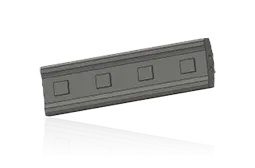
Blow Bars
Blow Bar
Mounted on the rotor under direct high-speed impact. Check section, length, weight, locking design, rotor slot, working-face direction and backing strips.
View the Component Page →Use current CI711–CI732 models to identify blow bars, impact plates, rotors, bearings, aprons, hydraulic adjustment parts and materials for quotation.
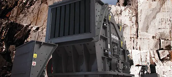
Models and key specifications identify the machine. Wear parts and general spares link to component and material pages. Drawings remain blank where no reliable match exists.
Weight, maximum feed, capacity and power come from Sandvik's current stationary HSI pages and support initial identification.
| Model | Weight | Maximum Feed | Capacity | Motor Power |
|---|---|---|---|---|
| CI732 | 29,650 kg | 350 mm | 250–575 t/h | 440 kW |
| CI731 | 27,750 kg | 1,000 mm | 400–700 t/h | 440 kW |
| CI722 | 16,256 kg | 350 mm | 150–250 t/h | 250 kW |
| CI721 | 16,000 kg | 900 mm | 200–400 t/h | 250 kW |
| CI712 | 11,184 kg | 300 mm | ≤150 t/h | 185 kW |
| CI711 | 11,005 kg | 600 mm | ≤200 t/h | 185 kW |
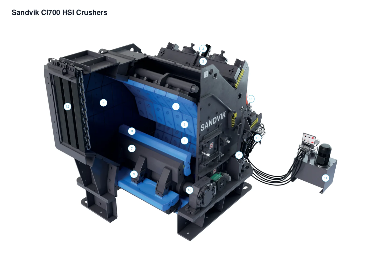
The numbers on the diagram correspond one to one with the rows below.
| No. | Component | Location | Applies to |
|---|---|---|---|
| 1 | First curtain | Curtain in the first crushing stage | CI700 OEM family view (dimensions not specified) |
| 2 | First curtain cross beam | Cross beam above the first curtain | CI700 OEM family view (dimensions not specified) |
| 3 | First curtain adjustment cylinder | Adjustment above the first curtain | CI700 OEM family view (dimensions not specified) |
| 4 | Second curtain | Second impact stage | CI700 OEM family view (dimensions not specified) |
| 5 | Curtain liners | Curtain working faces | CI700 OEM family view (dimensions not specified) |
| 6 | Frame liners | Frame inner walls of the crushing chamber | CI700 OEM family view (dimensions not specified) |
| 7 | Rotor | Lower crushing chamber | CI700 OEM family view (dimensions not specified) |
| 8 | Hammer / Blow bar | Rotor periphery | CI700 OEM family view (dimensions not specified) |
| 9 | Hammer locking wedge | Hammer-to-rotor connection | CI700 OEM family view (dimensions not specified) |
| 10 | Bearing housing | Outer rotor-shaft end | CI700 OEM family view (dimensions not specified) |
| 11 | Pivot frame cylinder | Rear-frame opening connection | CI700 OEM family view (dimensions not specified) |
| 12 | Primary feed hopper | Top inlet | CI700 OEM family view (dimensions not specified) |
| 13 | Hammer lifting jib | Lifting position above the frame | CI700 OEM family view (dimensions not specified) |
| 14 | Electric hydraulic powerpack | Separate module on the right | CI700 OEM family view (dimensions not specified) |
| 15 | Quick-release hydraulic fittings | External hydraulic-powerpack connection | CI700 OEM family view (dimensions not specified) |
Identify each position separately. Select materials for impact, abrasion, metal in feed, target particle shape, replacement access and current failure patterns.
Blow Bar
Mounted on the rotor under direct high-speed impact. Check section, length, weight, locking design, rotor slot, working-face direction and backing strips.
View the Component Page →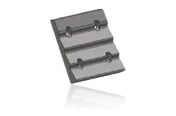
First Apron Liner
Take higher impact and erosion in the first stage. Check segment order, curvature, holes, thickness, overlap and apron location.
View the Component Page →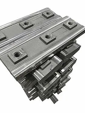
Second Apron Liner
Control shape and further size reduction. Check row position, curvature, holes, thickness and working clearance to the rotor.
View the Component Page →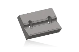
Third Apron Liner
For machines fitted with a third impact stage. Check configuration, position, segment count, holes, curvature and discharge gap.
View the Component Page →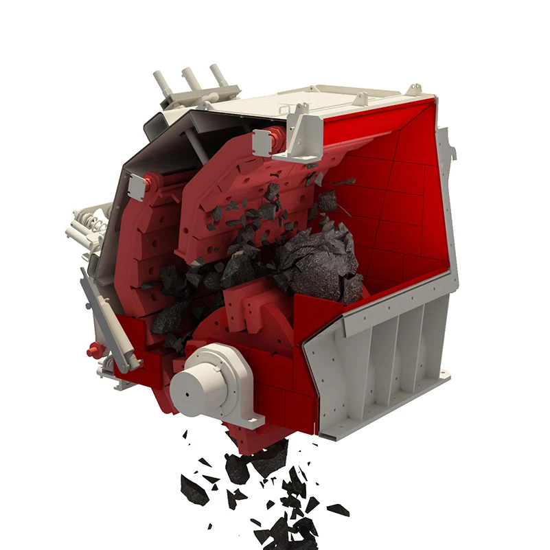
Side Liner
Protect body sides from ore friction. Check side, front/rear position, segment reference, holes, thickness and apron clearance.
View the Component Page →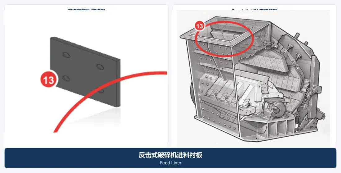
Feed Liner
Protect the feed passage and chamber entrance. Check segment sequence, feed direction, holes, thickness, overlap and safe clearance to rotor travel.
View the Component Page →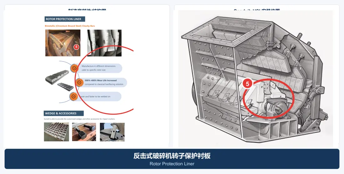
Rotor Protection Liner
Protect the rotor and bar mounting area. Check location, shape, holes, fasteners, weight balance and bar assembly interfaces.
View the Component Page →Verify drive, support, locking and hydraulic parts by full model, direction, key dimensions, fits, tolerances, pressure and assembly relationships.
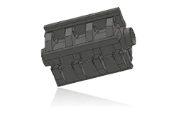
Rotor Assembly
The crusher's main high-speed rotating assembly. Check full model, diameter, width, bar slots, shaft ends, rotation, inertia, welding and balance.
View the Component Page →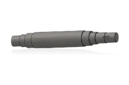
Rotor Shaft
Transmits motor power and supports the rotor. Check diameter, bearing seats, keyways, ends, rotation, material, heat treatment, runout and nondestructive testing.
View the Component Page →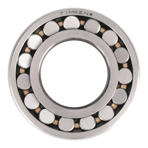
Rotor Bearing
Carry radial loads, impact and temperature rise. Check full designation, clearance, fits, tolerances, lubrication, seals and temperature monitoring.
View the Component Page →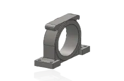
Bearing Housing
Locate and support bearings. Check side, centre height, mounting and bearing bores, tolerances, oil passages, seal interfaces and frame datums.
View the Component Page →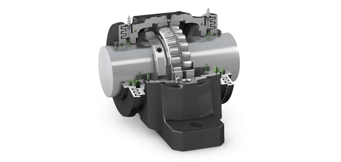
Rotor Bearing Seal
Exclude dust and retain lubrication. Check seal design, shaft diameter, direction, clearance, temperature, lubricant and end-cover interface.
View the Component Page →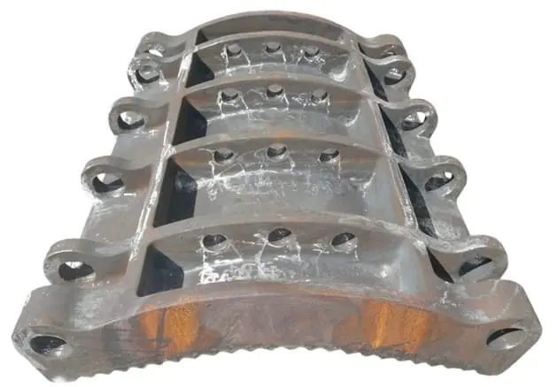
Impact Apron Assembly
Supports liners and forms the crushing gap. Check first/second/third stage, pivot shaft, supports, hydraulic interfaces, liner layout and working angle.
View the Component Page →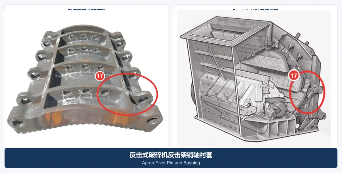
Apron Pivot Pin & Bushing
Support apron movement and adjustment. Check pin diameter, length, bushing diameters, oil grooves, retention, fits and orientation.
View the Component Page →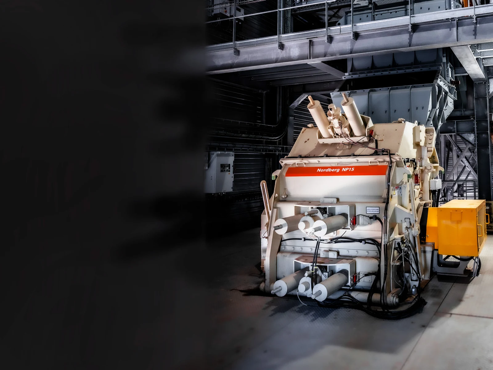
Apron Adjustment Cylinder
Adjust the crushing gap and move the apron. Check bore, rod diameter, stroke, trunnions, ports, pressure, seals and side.
View the Component Page →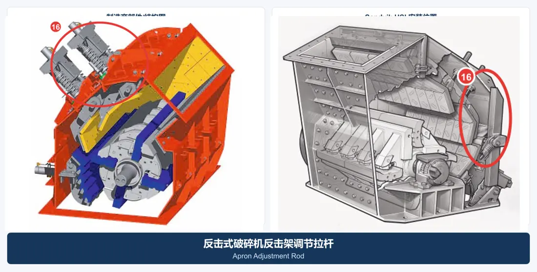
Apron Adjustment Rod
Connect the adjustment system and transfer preload or locating loads. Check length, thread, diameter, ends, springs and position.
View the Component Page →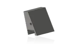
Blow Bar Retaining Wedge
Lock bars into rotor slots. Check angle, length, direction, contact faces, fastening and matching backing strips and bars.
View the Component Page →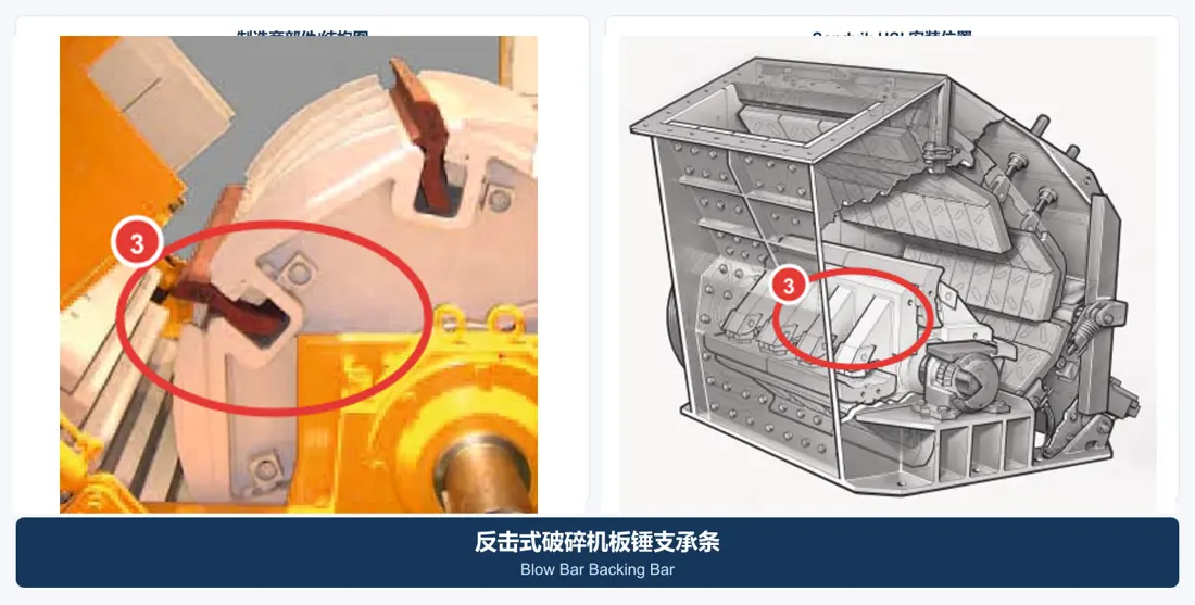
Blow Bar Backing Bar
Fit between bar and rotor locking system. Check section, length, faces, orientation and matching bar/wedge set.
View the Component Page →No. Check rotor slot, bar section, length, weight, lock, working direction, material and matching backing strips or wedges.
Not necessarily. Feed size, impact energy, abrasion, rotor speed, apron stages and gaps all influence bars and liners.
Yes. Send full model, serial number, location, photographs and key dimensions or drawings. We identify the part before confirming supply.
Provide full model, serial number, position, drawings or samples, photographs, drawings, material and duty for identification, material assessment, quality control and delivery.
Or contact us directly: +86 156 3797 3199
zzx@anranst.com
ANRANST provides customers worldwide with engineering assessment, production at certified foundries to the customer technical requirements, quality control and finished-part delivery for custom wear parts and industrial spares, with scope to support other custom industrial parts.
We review mating surfaces and interface dimensions and assess material, heat treatment and manufacturing feasibility.
Material grades and heat-treatment processes are specified order by order, stated in the technical agreement and tracked through production.
Drawing confirmation, material and process control, production tracking, inspection and acceptance coordination.
We coordinate manufacturing, quality confirmation, packaging and delivery of complete finished parts in a workable, closed-loop supply process.
Provide the existing model, drawings, drawing, materials or operating conditions so we can identify the appropriate technical review and supply route.
Submit an Enquiry