
01
Backup Rotor Tips
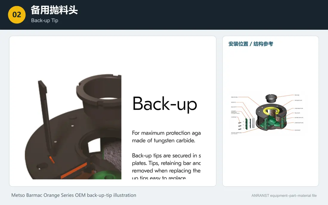
Back-up Tip
Located at rotor outlets, they continue protecting the rotor after main-tip wear. Check rotor model, handedness, holes, profile, matching tips and installation sequence.
View the Component Page →Use current CV215–CV229 models to identify rotor tip systems, feed parts, internal and external wear plates, main shafts, bearings, drives and materials for quotation.
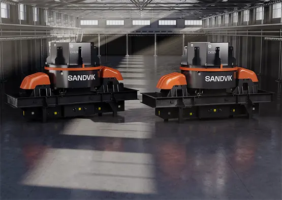
Models and key data identify the installation. Wear parts are grouped by rotor feed, discharge passages, internal/external protection and chamber position; shafts and drive parts are listed separately.
Weight, maximum feed, capacity and motor power come from current Sandvik stationary VSI product pages and support initial installation identification.
| Model | Weight | Maximum Feed | Capacity | Motor Power |
|---|---|---|---|---|
| CV229 | 14,826 kg | 55 mm | 445–600 t/h | 500 kW |
| CV228 | 14,826 kg | 55 mm | 271–444 t/h | 370 kW |
| CV218 | 11,776 kg | 55 mm | 193–270 t/h | 250 kW |
| CV217 | 9,500 kg | 50 mm | 122–192 t/h | 185 kW |
| CV216 | 9,500 kg | 50 mm | 51–121 t/h | 110 kW |
| CV215 | 6,000 kg | 40 mm | 10–50 t/h | 55 kW |
The numbers on the diagram correspond one to one with the rows below.
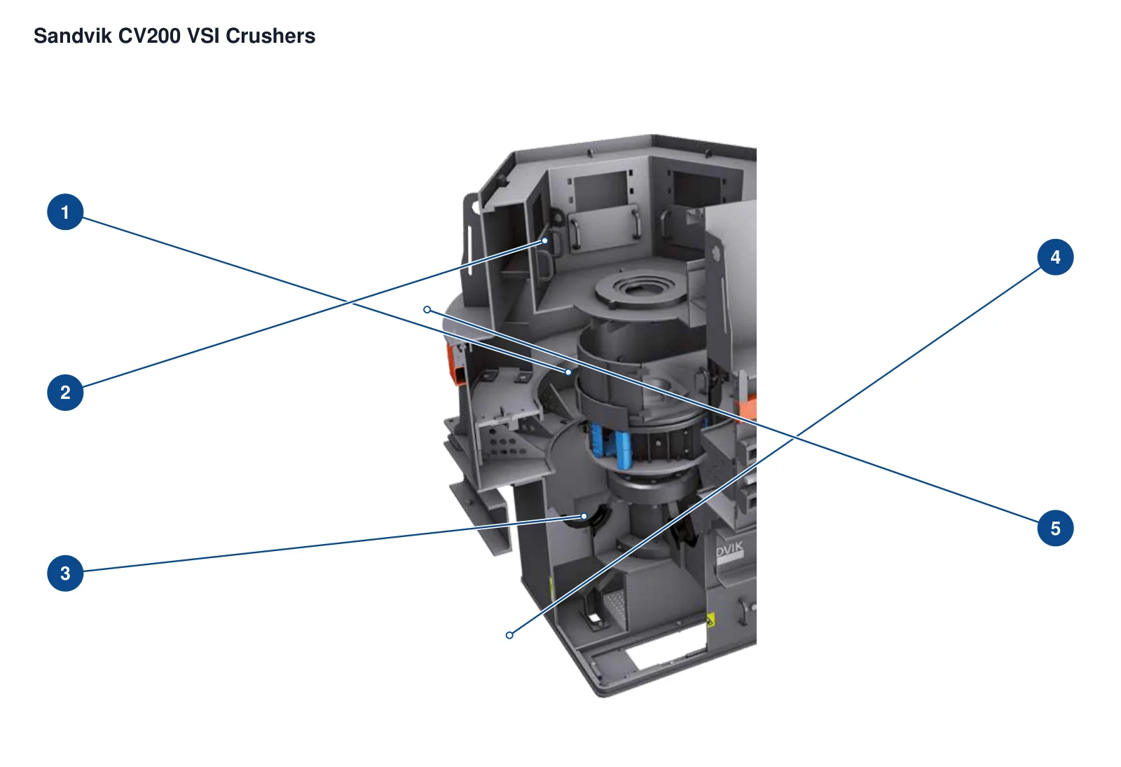
| No. | Component | Location | Applies to |
|---|---|---|---|
| 1 | Rotor | Central cylindrical rotating assembly | CV200 OEM family section (dimensions not specified) |
| 2 | Feed tube | From the top inlet to the rotor | CV200 OEM family section (dimensions not specified) |
| 3 | Main shaft assembly | Vertical support and drive beneath the rotor | CV200 OEM family section (dimensions not specified) |
| 4 | Drive motor | Motor module at the base | CV200 OEM family section (dimensions not specified) |
| 5 | Inspection door | Side opening into the crushing chamber | CV200 OEM family section (dimensions not specified) |
Identify each part by position. Material selection considers high-speed abrasion, centrifugal loads, local impact, fracture risk and rotor dynamic balance together.
Back-up Tip
Located at rotor outlets, they continue protecting the rotor after main-tip wear. Check rotor model, handedness, holes, profile, matching tips and installation sequence.
View the Component Page →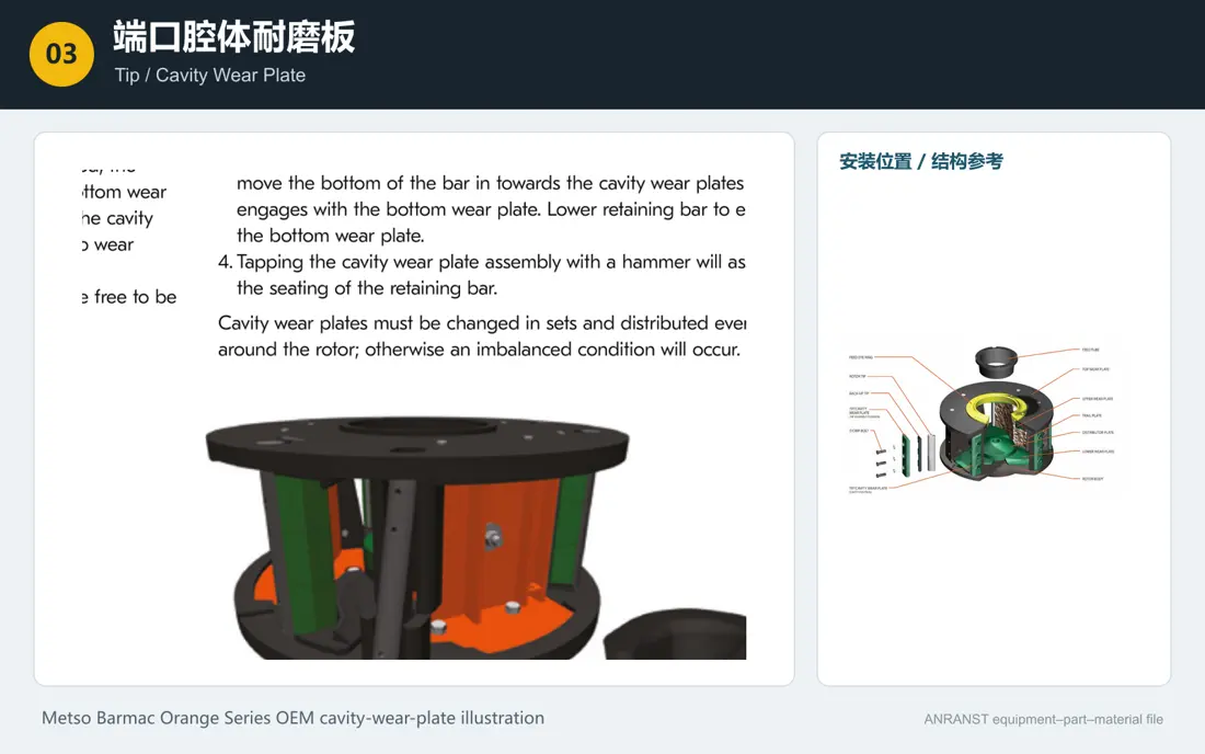
Tip Cavity Wear Plate
Protect the rotor cavity near the tips. Check rotor ports, orientation, plate profile, holes, thickness and compatibility with the tip system.
View the Component Page →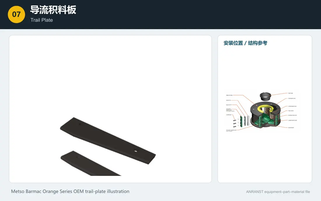
Trail Plate
Installed in trailing areas of rotor discharge passages, they face high-speed flow erosion. Check position reference, direction, curvature, holes and overlaps with upper/lower wear plates.
View the Component Page →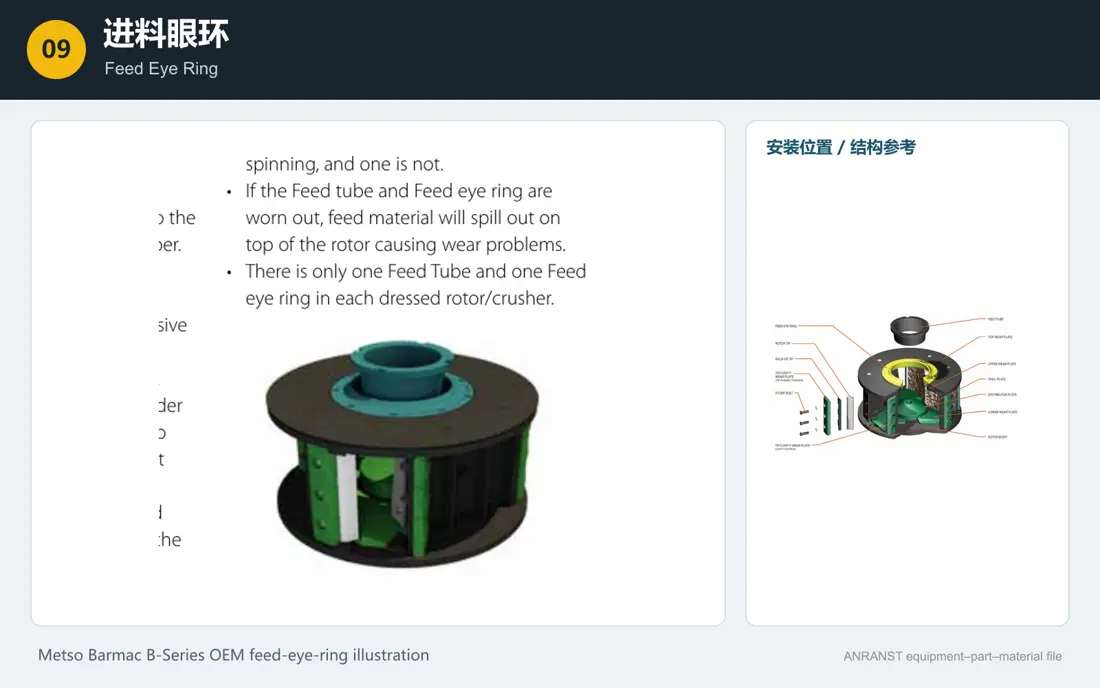
Feed Eye Ring
At the central rotor inlet, it guides feed and protects the edge. Check inside/outside diameters, thickness, holes, locating features and feed-tube clearance.
View the Component Page →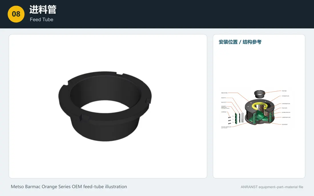
Feed Tube
Directs material into the rotor centre. Check diameters, length, flange, installation height, concentricity, flow direction and fit with the feed eye ring.
View the Component Page →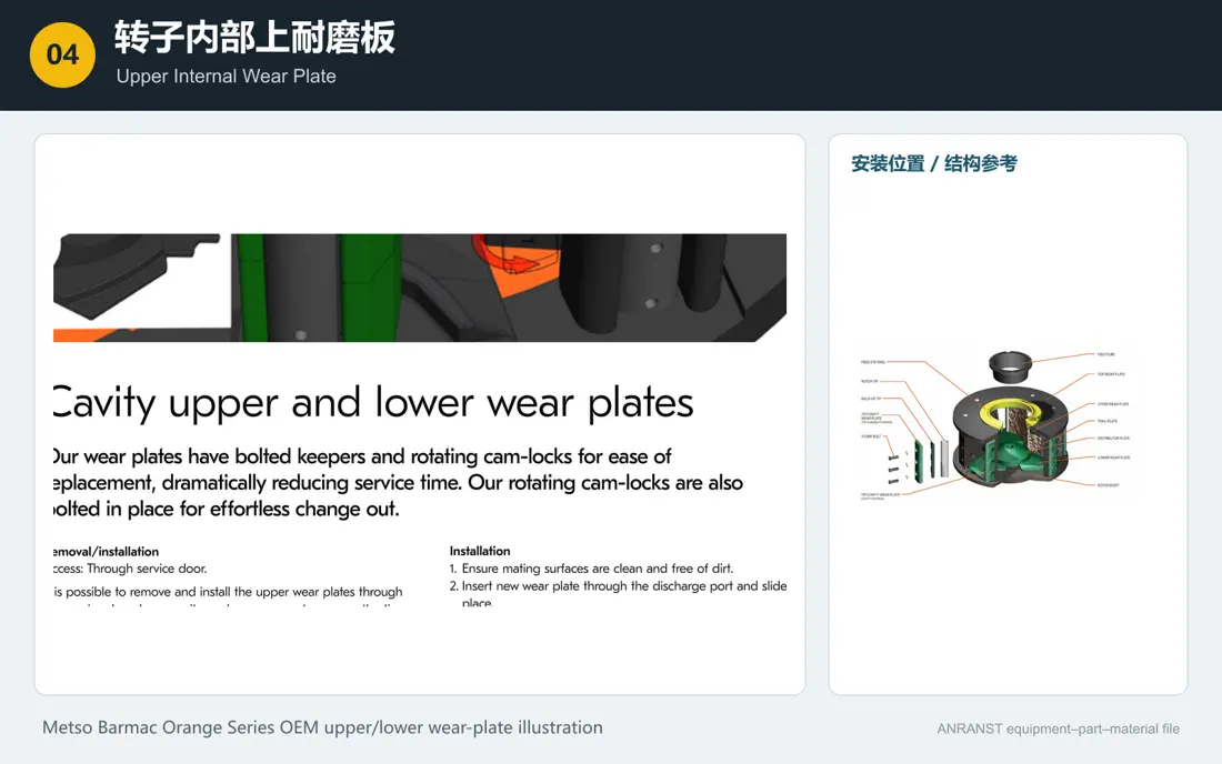
Upper Internal Wear Plate
Protect upper internal rotor flow passages. Check position, direction, holes, curvature, thickness and overlaps with adjacent plates.
View the Component Page →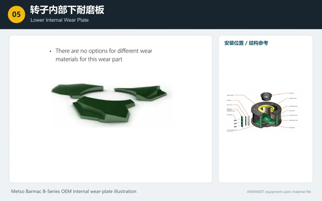
Lower Internal Wear Plate
Protect lower internal rotor passages. Check position, direction, segment sequence, holes, thickness and relationship with external plates.
View the Component Page →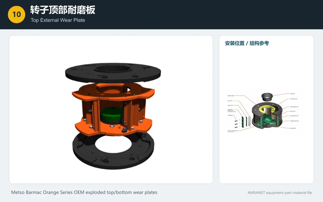
Top External Wear Plate
Protect exposed top rotor surfaces. Check rotor specification, orientation, holes, thickness, profile and dynamic clearances.
View the Component Page →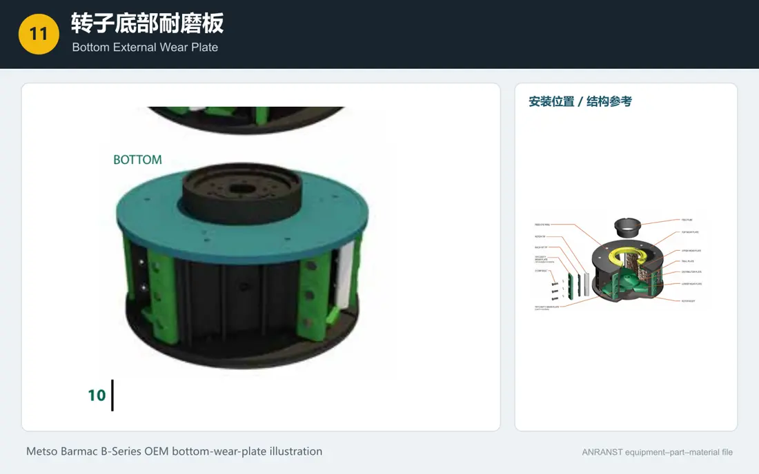
Bottom External Wear Plate
Protect the rotor's external bottom area. Check top/bottom orientation, direction, holes, thickness, profile, clearances and relationship with base guards.
View the Component Page →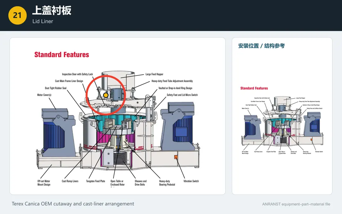
Lid Liner
Protect the chamber lid's inner surface. Check segment references, direction, holes, thickness, overlaps, access openings and rotor-sweep clearances.
View the Component Page →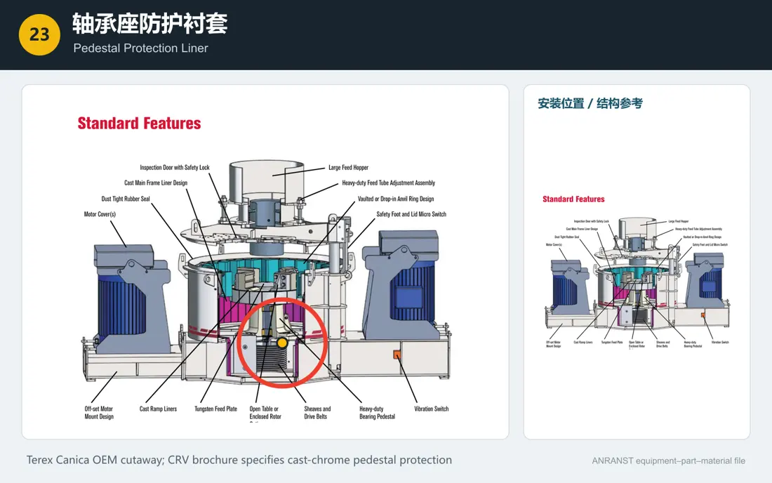
Pedestal Protection Liner
Protect the bearing pedestal and surrounding lower structure. Check installation zone, segmentation, holes, thickness and safe clearance to rotor bottom plates.
View the Component Page →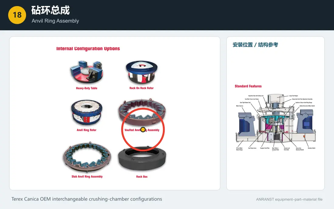
Anvil Ring Assembly
For installations configured for anvil crushing. Check crushing mode, ring dimensions, anvil count, positions, fastening and alignment with rotor discharge trajectories.
View the Component Page →Verify drive and support parts by full model, rotor specification, speed, direction, fits, tolerances, lubrication and dynamic balance.
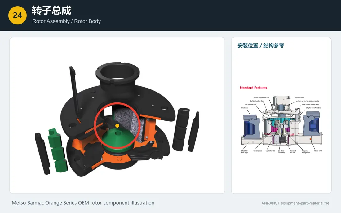
Rotor Assembly / Rotor Body
The VSI's main high-speed rotating assembly. Check rotor specification, diameter, ports, feed eye, discharge passages, shaft interface, rotation and balance requirements.
View the Component Page →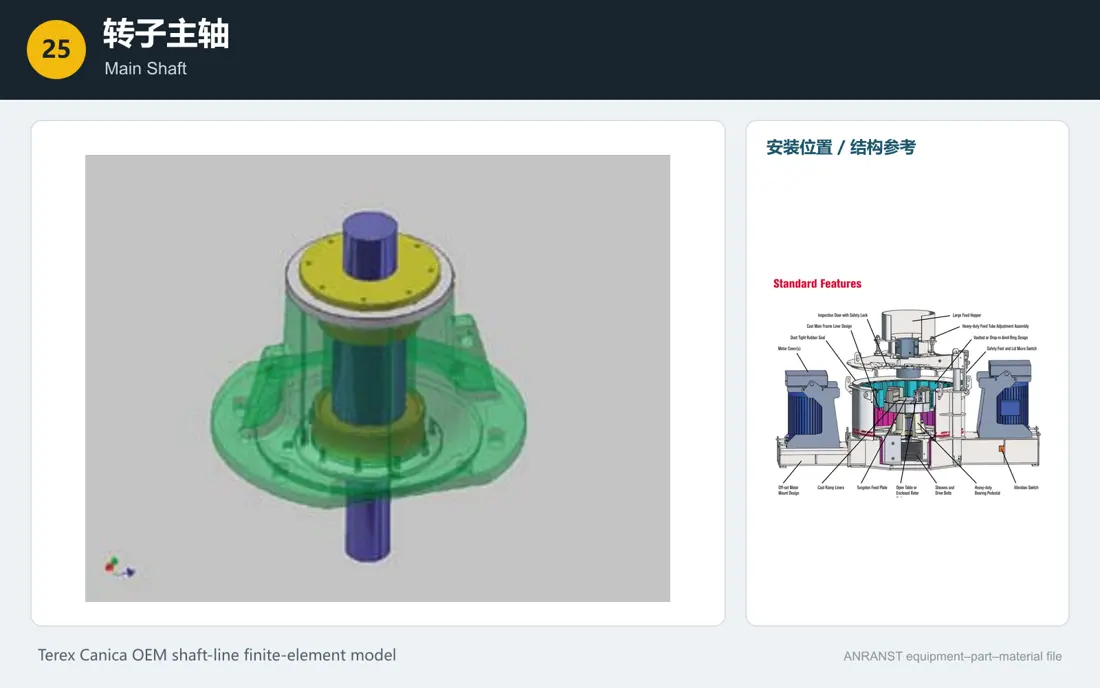
Main Shaft
Supports and drives the rotor. Check shaft diameters, bearing seats, taper-bush or key connection, ends, rotation, runout, heat treatment and non-destructive testing.
View the Component Page →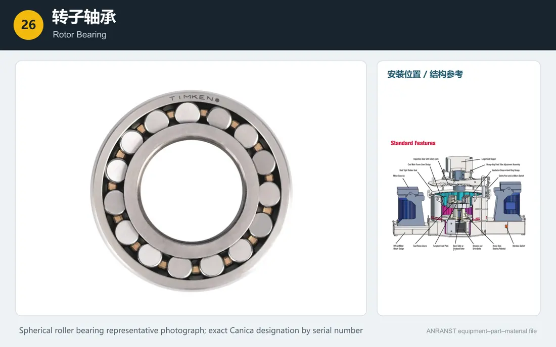
Rotor Bearing
Carry high-speed rotor loads. Check full bearing designation, clearance, fits, tolerances, speed, lubrication, seals, temperature rise and vibration monitoring.
View the Component Page →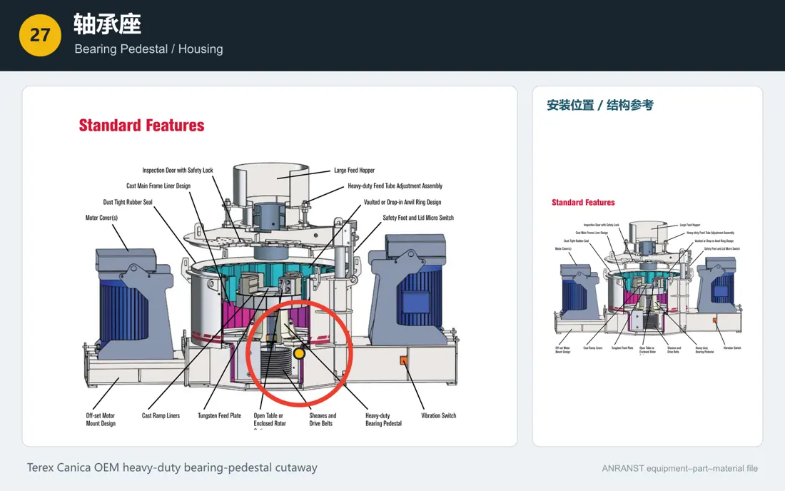
Bearing Pedestal / Housing
Locate main-shaft bearings and connect them to the frame. Check centre height, mounting and bearing bores, tolerances, oil passages, seal interfaces and datum surfaces.
View the Component Page →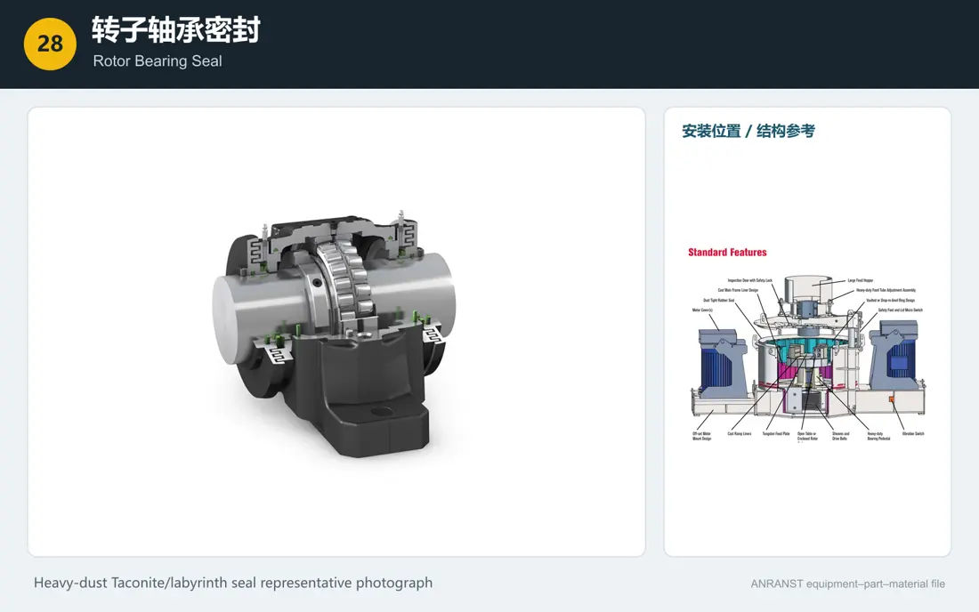
Rotor Bearing Seal
Exclude dust from high-speed bearings and retain lubrication. Check shaft diameter, seal design, direction, clearances, lubricant and operating temperature.
View the Component Page →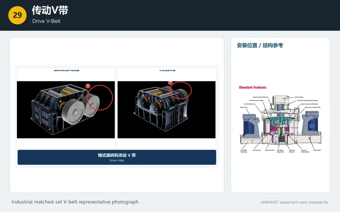
Drive V-belt
Transmit power from the motor to the main shaft. Check belt section, length, count, matched-set tolerances, pulley diameters, centres and tensioning.
View the Component Page →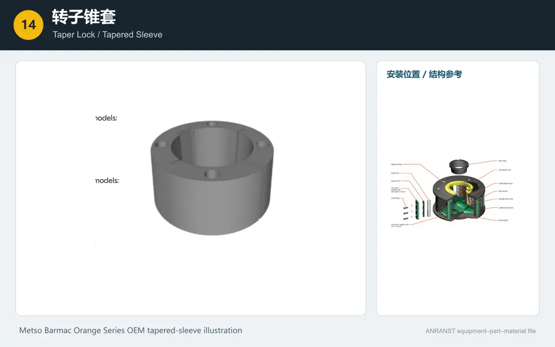
Taper-lock / Tapered Sleeve
Provide tapered locking between pulleys or rotating parts and shafts. Check taper, inside/outside diameters, keyways, bolt holes, shaft diameter and mating pulley.
View the Component Page →No. Also check rotor specification, ports and crushing mode, position, direction, part drawing, key dimensions, material and matched assemblies.
First verify rotor design and matched-part relationships. Similar shape does not imply identical position, direction, clearance, weight or balance requirements.
Yes. Send the full model, serial number, rotor and used-part photographs, position, key dimensions or drawings so we can first identify the part technically.
Provide the full model, serial number, rotor specification, position, drawings or samples, used-part photographs, drawings, material and duty. These support identification, material assessment, quality control and finished-part delivery.
Or contact us directly: +86 156 3797 3199
zzx@anranst.com
ANRANST provides customers worldwide with engineering assessment, production at certified foundries to the customer technical requirements, quality control and finished-part delivery for custom wear parts and industrial spares, with scope to support other custom industrial parts.
We review mating surfaces and interface dimensions and assess material, heat treatment and manufacturing feasibility.
Material grades and heat-treatment processes are specified order by order, stated in the technical agreement and tracked through production.
Drawing confirmation, material and process control, production tracking, inspection and acceptance coordination.
We coordinate manufacturing, quality confirmation, packaging and delivery of complete finished parts in a workable, closed-loop supply process.
Provide the existing model, drawings, drawing, materials or operating conditions so we can identify the appropriate technical review and supply route.
Submit an Enquiry