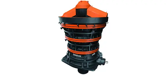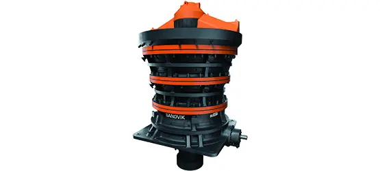
Sandvik CG800i Gyratory Crushers

From CG810i, CG820i, CG830i and CG850i Standard Models Entrance Spider and Liners Abrasion system, Main Shaft and Eccentric Bushing, Power Transmission Hydraulics, drawing number Confirmation and RFQ.

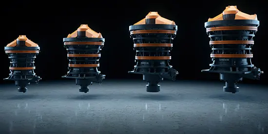
Sandvik CG800i Gyratory Crusher Official Series Figures
Sandvik Official CG800 gyratory crusher Series Graphs; specific installers CG810i, CG820i, CG830i or CG850i and serial number Confirmation.
OEM Equipment Details

model, wear parts and spare parts Completed on a page

CG800i — — This page retains only official specifications, core installment positions and material check-in cording to the distribution of Spare parts. The Open Model Card uses its current shortcut for technical table names in a series called "CG"

4 Current Standard Models
1,067–1,549 mm Feed Inlet
1,300–8,250 t/h Scope of official capacity
315–950 kW Installed Power
Standard Models and Key Dimensions

CG810i, CG820i, CG830i, CG850i

The following weight, Feed Inlet Power and power come from Sandvik Current CG800i Official Specifications; and finally nameplate, serial number smashing cavity Configuration and Equipment Documents confirmed.

ModelEquipment WeightFeed InletAbilityMotor Power
CG810i128 t1,067 mm1,300–2,700 t/h315 kW
CG820i244 t1,372 mm1,500–4,000 t/h525 kW
CG830i380 t1,525 mm2,700–6,000 t/h660 kW
CG850i500 t1,549 mm3,800–8,250 t/h950 kW
Sandvik CG810 Official full-length diagram
CG810 / CG810i: 42 in Feed Inlet Levels.
Sandvik CG830 Official full-length diagram
CG830 / CG830i: 60 in Feed Inlet Levels.
Sandvik CG850 Official full-length diagram
CG850 / CG850i: 61 in Feed Inlet Levels.

Capacity with ore characteristics, feed distributions and crushing cavity closed-side setting and changes in operating conditions; this table is used Installation Identification, not substitute Item Selected and original file.

Wear Parts

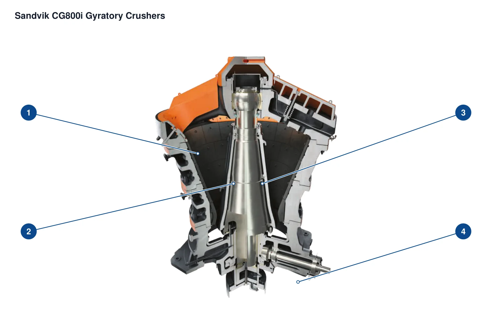
Spider, concave, mantle and Housing Abrasion system

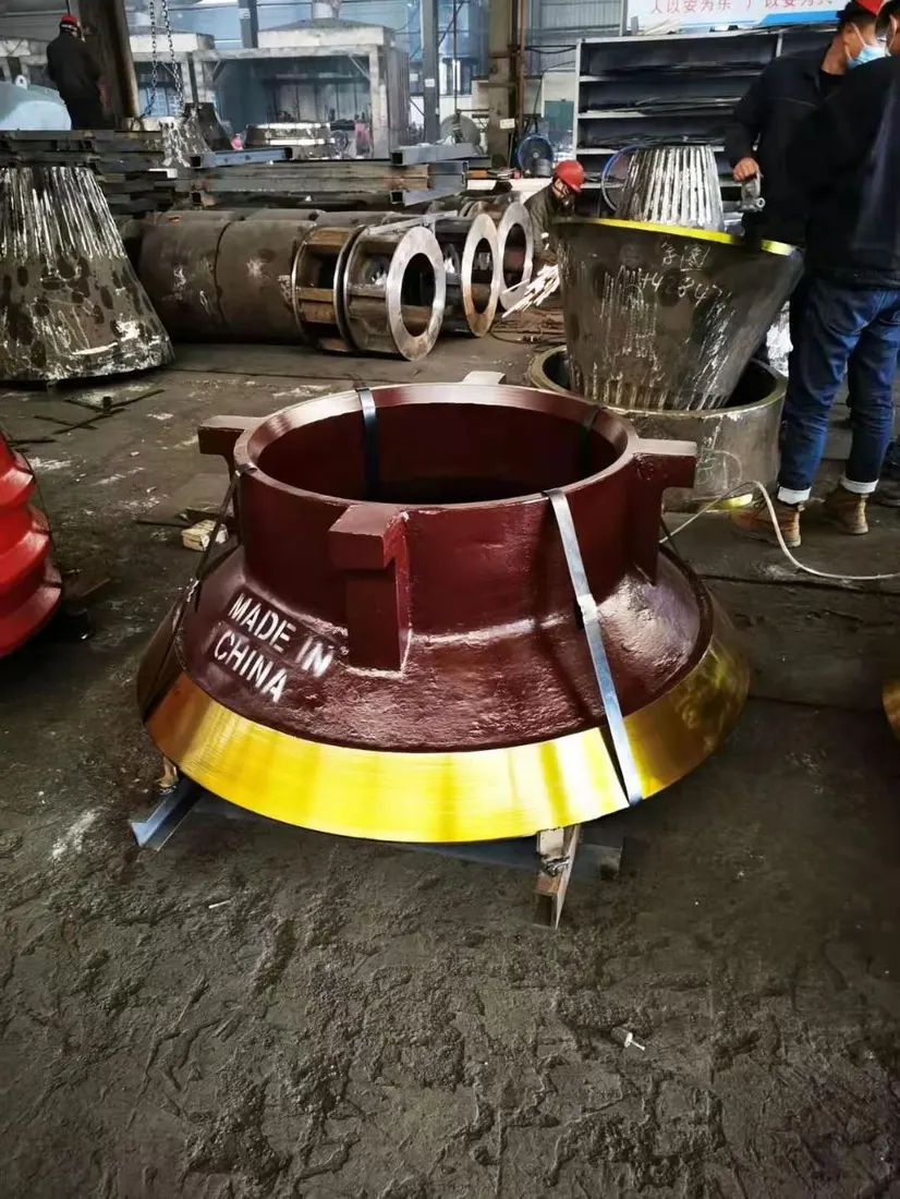
Priority displays are bulgings, convexliner and mantle liners as well with mainstay protection; each card specifies the installation position of a device that is configured to match its focus on equipment conditions.

Spider stern, Spider Hats and Arm Guard Identification Figures
01

Spider stern, Spider Hats and Arm Guard

Spider Cap, Shield & Arm Liner

Locations Feed Inlet Above, directly withstand the large ore impact and overload. sliding wear. Converged Spider Construction, number of arms and plate type; hole system: thicknesses.

Material Selection: high-manganese steel, Quenched and Tempered Wear Plate or Composite wear-resistant construction Confidentialized by impact energy, plate thickness and fixed manner.

View Part Details →
gyratory crusher Mantles and Concaves System General Indications
02

Concave Liner

Concaves

Walks along Housing Sub-paragraph Mounting, and mantle Forming a fractured cavity. Contrast cavity profile, number of layers and fragments; the bearing ring.

Material Selection: s high-manganese steel The system is the main candidate, specific labels and chemical composition. heat treatment and zoning programmes by ore operating conditions Confirmation with the original drawings.

View Part Details →
gyratory crusher Mantles and Concaves System General Indications
03

Mantle

Mantle

Package Main Shaft Cone and with Main Shaft sloppy, and concave Together, complete the break. Contrast up and down profile Head nut Interfaces siding, closed-side setting and wearable partitions.

Material Selection: s high-manganese steel The system is the main candidate; materials and heat treatment Combining feed granularity, impact intensity and ore Hardness Recognizes the wear record.

View Part Details →
Main Shaft Protective Sleeve Identification Figures
04

Main Shaft Protective Sleeve

Mainshaft Protective Sleeve

Installed outside the mainshaft to protect its working surface; it is a separate single piece, not equivalent of either spindle or head shackle. Contrast internal and external diameters / length & stop-over with cohesion

Material Selection: Bases, surface Hardness, heat treatment The requirements for the matching must be confirmed according to original design, and cannot use Main Shaft materials replace.

View Part Details →
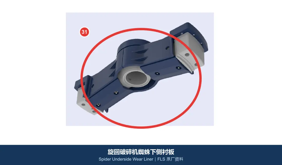
Spider s side liners Identification Figures
05

Spider s side liners

Spider Underside Wear Liner

Protection Spider The surface and adjacent areas are subjected to blasts, rebounding or mineral flows. Contrast the left-hand direction of plate layout; hole lines Spider slanted face.

Material Selection: Manganese steel or quenched and tempered abrasion-resistant plate By impact and sliding wear Proportionally Selected, Construction The welding parts must be reconciled with the solderability at once.

View Part Details →
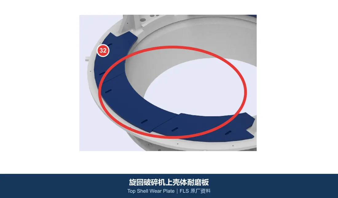
Upper Housing Wear Plate Identification Figures
06

Upper Housing Wear Plate

Top Shell Wear Plate

Protection of protection Housing Feeding and rebound areas. Converged Mounting partitioning, plate thicknesses and arcades; fitting with the connection. Construction and the concave liner Borders.

Material Selection: Quenched and Tempered Wear Plate, high-manganese steel or Composite wear-resistant construction By impact, abrasive wear and Installation Confirmation.

View Part Details →
Spare Parts

Spider, Main Shaft, Eccentric Bushing, gear, bearing Hydraulic sealing

The large shafts are separately identified with the main axle protection boomings; transmission, bearing and hydraulic sealing is verified by series of complete models.

Spider Assembly Identification Figures
01

Spider Assembly

Spider Assembly

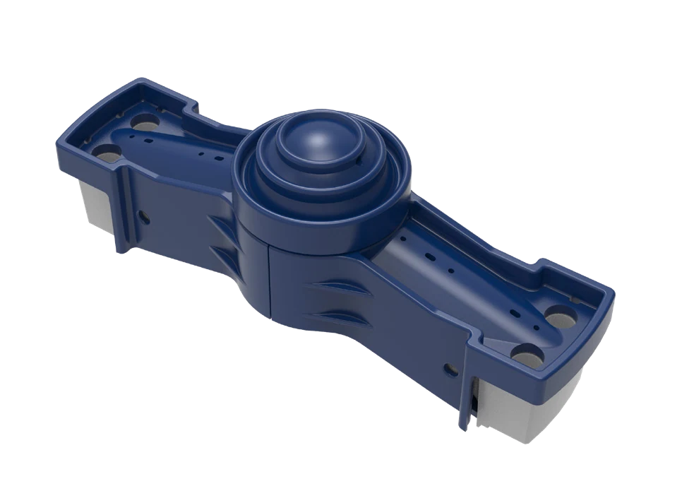
The whole graph is used Identification Top Spider installation position. Consolidation of the total Spider Arms Construction, the center of affinity and connection flange. bushings Floor and full Model No.

Material Selection: Large Cast Steel Or welding Construction, Connectors and Bearings materials Graphics, loads and NDT Requests for confirmation.

View Part Details →
Main Shaft (Big Axes) Identification Figures
02

Main Shaft (Big Axes)

Mainshaft

The whole diagram is used to identify the central axis of a spindle, not as single physical. It carries core parts and must be checked separately from external mains protection bushshinges

Material Selection: Large Forged Alloy Steel, heat treatment axis and neck precision, straightness NDT by complete model, payloads and original drawings confirmed.

View Part Details →
Pillars bushings With oil seals Identification Figures
03

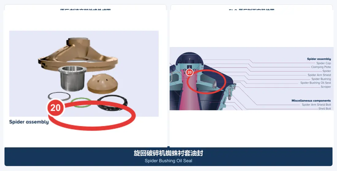
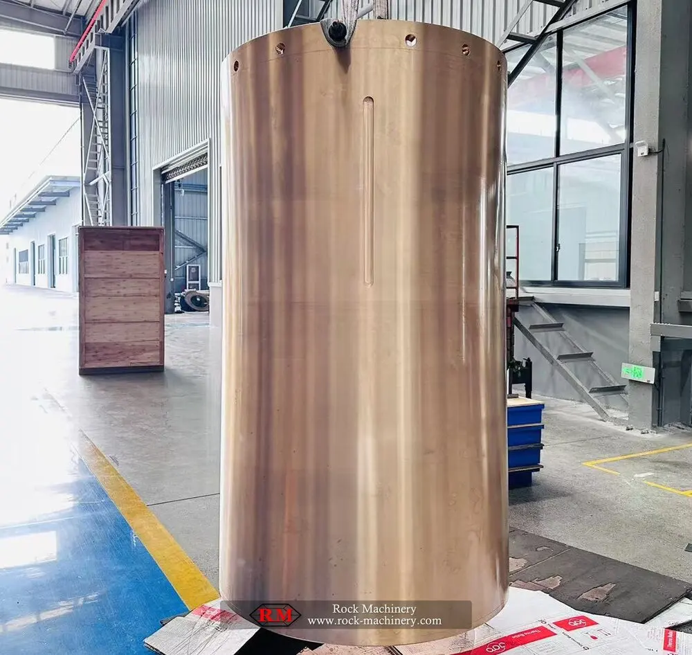
Pillars bushings With oil seals

Spider Bearing & Oil Seal

The pivot Main Shaft On the top and keep lubrication sealed. Contrast spherical bearings Construction axis, and bushings Internal and external diameters, flanges or oil rigging.

Material Selection: Copper Alloys for Bearings Steel fittings and Seal Materials Recognize by load, lubrication mode and temperature as well.

View Part Details →
gyratory crusher eccentric bushing General Ideas
04

Eccentric Bushing

Eccentric Bushing

In the eccentric body, forming and bearing Main Shaft. Contrast the polarization of distance, internal and external diameters; up-toe direction: oil sinking point Working clearances.

Material Selection: Copper Alloys for Bearings.Certificate and casting Quality, oil tank and matching gap by loads of the loading. Lubrication with original drawings confirmed

View Part Details →
gyratory crusher Gear Wheel General Ideas
05

Gear Wheel

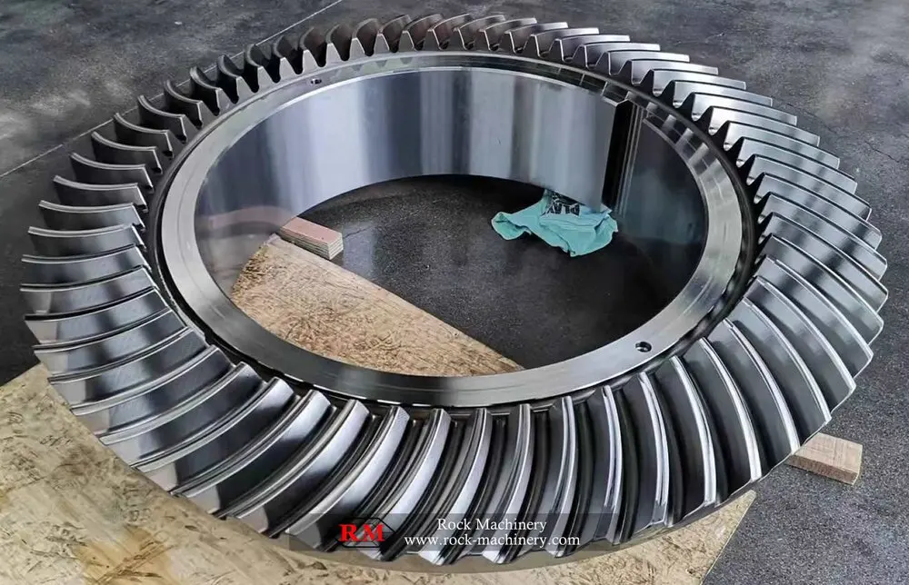
Bevel Gear

Pictures for Cone gear Power Transmission Category Identification. Gear Wheel. Must and pinion The number of pairs, the numbers teeth and pressure angles are paired with a spiral direction; Mounting Distance and Contact stained.

Material Selection: Carbon permeation or morphology Alloy Steels for Drive Parts Touching the teeth Hardness, core toughness and accuracy of pairing Inspection Confirmed according to the original design.

View Part Details →
pinion Identification Figures
06

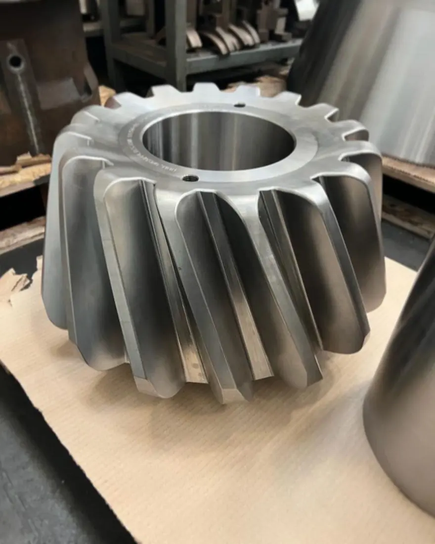
Pinion

Pinion

and Gear Wheel The pairing of horizontal axis power. Converging number, rotational parameters and axes Interfaces, and the record of a pairing.

Material Selection: Forged Alloy Steels for Drive Parts and corresponding heat treatment, by torque and impact loads. Hardness and the sturdyness of your heart.

View Part Details →
Pinion Shaft Bearing Identification Figures
07

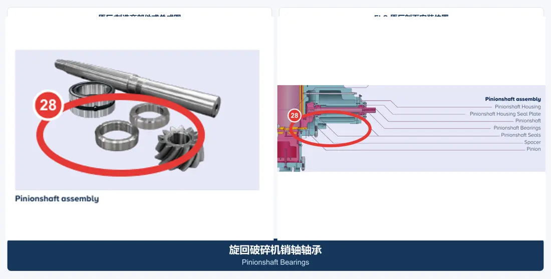
Pinion Shaft Bearing

Pinionshaft Bearings

Level of sizing Pinion Shaft and maintain gear The center distance. Convergence bearing model, the gaps and load direction of axle neck & seat hole tolerance as well.

Material Selection: bearing Steel, slab and accessories for the use of materials by Speed, loads and temperature risers bearing Specifications confirmed.

View Part Details →
Pinion Shaft Seal Identification Figures
08

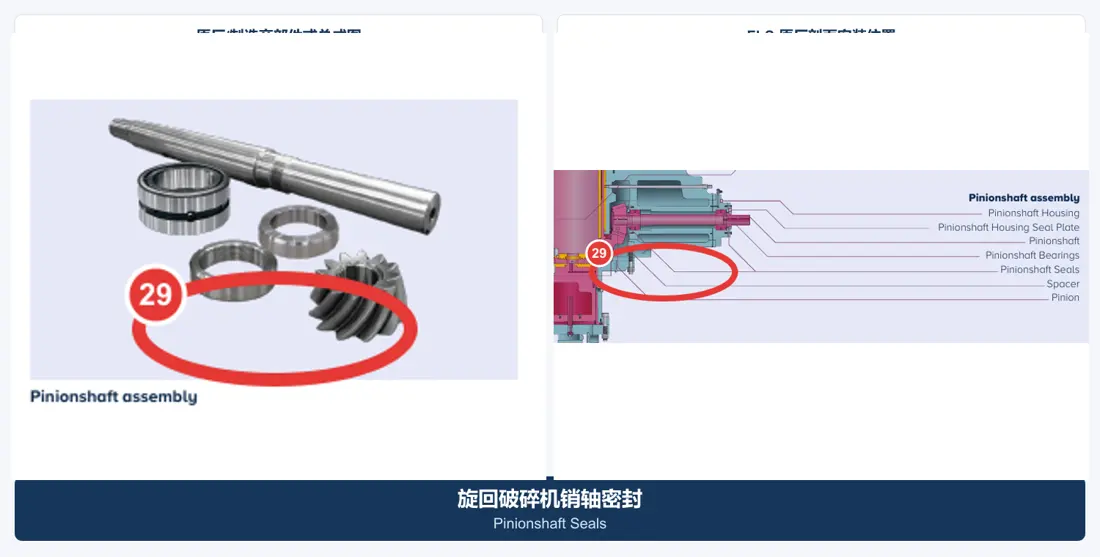
Pinion Shaft Seal

Pinionshaft Seals

Separation of dust and preservation Power Transmission lubricating the box. Converging axle diameter, Refining Grooves lip direction, temperature and oil products. Speed The top Construction.

Material Selection: NBR, HNBR, FKM, polyurethane Other Works Seal Materials Recognized by temperature, medium and mode of movement.

View Part Details →
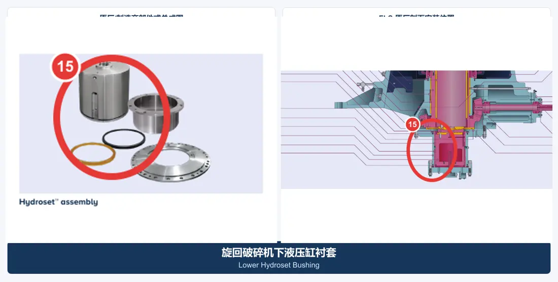
Hydroset Bushings Identification Figures
09

Hydroset Bushings

Hydroset Bushings

Hydraulic adjustment and Main Shaft The bearing system: check the upper and lower position, internal or external diameters of axle height; oil tanking with gap-convenient systems Interfaces.

Material Selection: Copper Alloys for Bearings Hydraulics and hydraulic Construction Steel parts are confirmed by surface pressure, lubrication and size stability.

View Part Details →
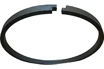
Hydroset Piston seals Identification Figures
10

Hydroset Piston seals

Hydroset Piston Seal

Keep the hydraulic adjustment system pressure and isolate contaminants. Contrast cylinder diameter, rod radius Refining Grooves, pressures and temperature of the medium in combination with sealing directions.

Material Selection: polyurethane, NBR, HNBR, FKM, PTFE or composite seals are confirmed by pressure, medium and temperature.

View Part Details →
Dust Seal System Identification Figures
11

Dust Seal System

Dust Sealing System

Protection of eccentric and lube areas, sealing the ring; Refining Grooves, Contact Faces, sweeping or overpressure conditions and accessories Dust collar Construction.

Material Selection: elastomers, polyurethane or engineered plastics are confirmed by dust, temperature and oil products as well the relative motion.

View Part Details →
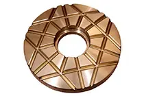
Main Shaft Step Plate Conclusions Identification Figures
12

Main Shaft Step Plate Conclusions

Step Bearing Components

Receivers Main Shaft Axle loads work in conjunction with hydraulic adjustment systems. Converging the order, Contact Diameter, oil film gaps and stop-topping surfaces as well assembly height.

Material Selection: Wear-Resistant Alloy Steel and Copper Alloys for Bearings Confirm by surface pressure, lubrication and flatness requirements.

View Part Details →
Drawing and Spare Part Numbers

Numbers must correspond to specific model, installation position and Drawing Revision

CG800i — — The local nuclear information has not yet formed a list of publicly rebuttable CGs dedicated part numbers, so this page does NOT create the number. After receiving complete data OEM drawing or third party portion count correspond to model and parts name respectively as well for installation positioning with core size

Open Principles: Only posters can be traced back model, installation position and the original base number; OEM drawing number With third parties spare parts The column records, not mixed and uncounted.

CG810, CG820, CG830, CG850 and CG810i How do you understand the name?

CG810 / CG820 / CG830 / CG850 / CG810i / CG820i / CG830i / CG850i — / / / / / / / — Sandvik Current Product Cards CG, CG, CG, CG abbreviated official Technology Tables and manual usage CGi, CGi, CGi, CGi; RFQ. when nameplate Full name and serial number OK, for sure (;;;;;;; )

Main Shaft and Main Shaft Protective Sleeve Is it the same? parts ?

No. Main Shaft loaded Core Parts, Main Shaft Protective Sleeve y Mounting Main Shaft Externally independent protections, both check-in drawing number Scales and materials.

Why this page does not show unconfirmed CG Specialized part number ?

The part number must be traced back to the specific model, installation position and drawing version. It is not computed publicly when there are no reliable bases; it can submit OEM or third-party numbers for matching checks

Submission Sandvik CG model, drawing number, Liners scattering or spare parts Demand

Provide complete model, serial number / OEMs or third party numbers and drawings of used parts materials as well for operation conditions. We are able to perform part identification (part recognition), material assessment; manufacturing matching - quality control & finished-party delivery accordingly).

Manufacturing Services in China

From Technical Assessment to Finished-Part Delivery

ANRANST provides customers worldwide with coordinated consulting, supplier sourcing, quality control and finished-part delivery for custom parts, wear parts and industrial spares from China, with scope to support other custom industrial parts.

01

Technical Advice

Equipment and part identification, drawing review, material selection and manufacturing feasibility assessment.

02

Supplier Introductions

Match requirements with suitable manufacturers in China and coordinate the exchange of technical information.

03

Quality Control

Drawing confirmation, material and process control, production tracking, inspection and acceptance coordination.

04

Finished-Part Delivery

Coordinate manufacturing, quality confirmation, packaging and delivery of complete finished parts.

Provide the existing model, drawings, drawing or part numbers, materials or operating conditions so we can identify the appropriate technical review and supply route.

Submit an Enquiry