Sandvik الكسارات الدورانية CG800i

Start with CG810i, CG820i, CG830i and CG850i models to identify spider and liner systems, mainshafts, bushings, drive and hydraulic parts, then confirm drawings and request a quotation.

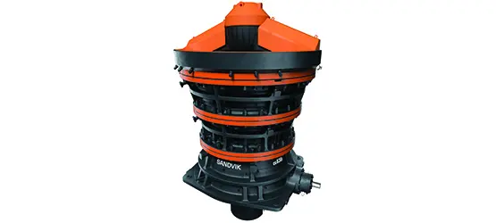
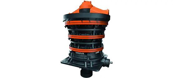
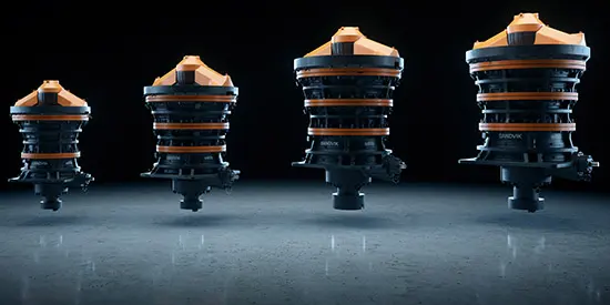
Official Sandvik CG800i gyratory crusher family image
Official Sandvik CG800 gyratory crusher family image. Confirm the installed CG810i, CG820i, CG830i or CG850i model and serial number.
OEM المعدات Reference

Models, wear parts and spares on one page

This page covers official specifications, key installation positions, material checks, drawing identification and enquiries relevant to spare-part supply. Model cards use the current short names on the manufacturer's website; the technical table retains CG800i designations.

4 Current standard models
1,067–1,549 mm Feed opening
1,300–8,250 t/h Published capacity range
315–950 kW Installed power
Standard models and key dimensions

CG810i, CG820i, CG830i, CG850i

Weights, feed openings, capacities and power ratings below come from Sandvik's current official CG800i specification table. Confirm the installed machine using its nameplate, serial number, chamber configuration and equipment documents.

ModelMachine weightFeed openingCapacityMotor power
CG810i128 t1,067 mm1,300–2,700 t/h315 kW
CG820i244 t1,372 mm1,500–4,000 t/h525 kW
CG830i380 t1,525 mm2,700–6,000 t/h660 kW
CG850i500 t1,549 mm3,800–8,250 t/h950 kW
Official Sandvik CG810 machine image
CG810 / CG810i: 42 in feed-opening class.
Official Sandvik CG830 machine image
CG830 / CG830i: 60 in feed-opening class.
Official Sandvik CG850 machine image
CG850 / CG850i: 61 in feed-opening class.

Capacity varies with ore properties, feed distribution, chamber, discharge setting and operating conditions. This table supports machine identification and does not replace project sizing or original equipment documents.

قطع الغيار المستهلكة

Spider, concave, mantle and shell wear protection

Spider protection, concaves, mantles and mainshaft sleeves are shown first. Each card identifies the installation position, service conditions and material checks, with a link to the shared component page.

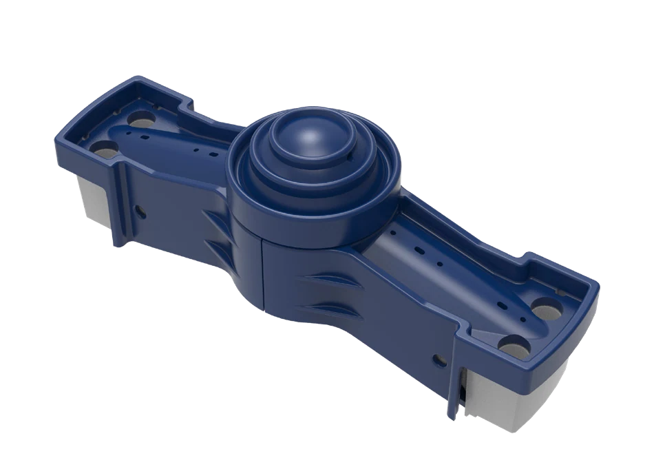
Spider shields, cap and arm liners identification image
01

Spider Shields, Cap and Arm Liners

Spider Cap, Shield & Arm Liner

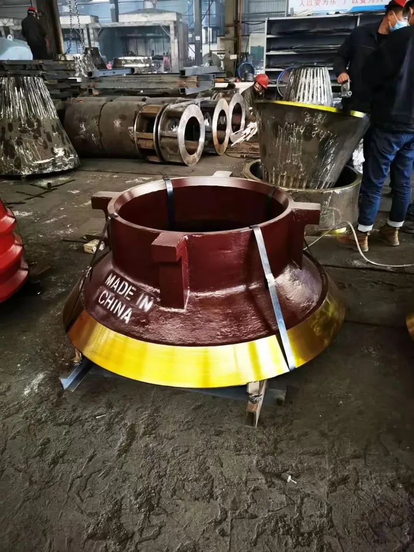
Above the feed opening, these parts face direct impact from large rocks, uneven loading and sliding wear. Check spider geometry, arm count, plate profile, hole pattern, thickness and feed direction.

Material selection: Confirm manganese steel, quenched-and-tempered wear plate or composite protection against impact energy, thickness and fastening method.

View the common part page →
Generic gyratory crusher mantle and concave system
02

Concaves

Concaves

Segments line the upper shell and form the chamber with the mantle. Check chamber type, tiers, segmentation, support rings, backing clearance and wear profile at each tier.

Material selection: Manganese steel is the main candidate. Confirm grade, chemistry, heat treatment and zoning against ore conditions and original drawings.

View the common part page →
Generic gyratory crusher mantle and concave system
03

بطانة المخروط المتحرك

بطانة المخروط المتحرك

The mantle covers the mainshaft head and moves with the gyrating shaft to crush against the concaves. Check upper and lower profiles, head-nut interface, backing, discharge setting and wear zones.

Material selection: Manganese steel is the main candidate; confirm material and heat treatment against feed size, impact severity, ore hardness and wear records.

View the common part page →
Mainshaft protective sleeve identification image
04

Mainshaft Protective Sleeve

Mainshaft Protective Sleeve

Mounted around the mainshaft to protect its working surface. This separate component is neither the mainshaft nor the mainshaft assembly. Check bore, outside diameter, length, locating shoulders and fits.

Material selection: Confirm base material, surface hardness, heat treatment and fits against the original design; the mainshaft material is not a substitute specification.

View the common part page →
Spider underside liner identification image
05

Spider Underside Wear Liners

Spider Underside Wear Liner

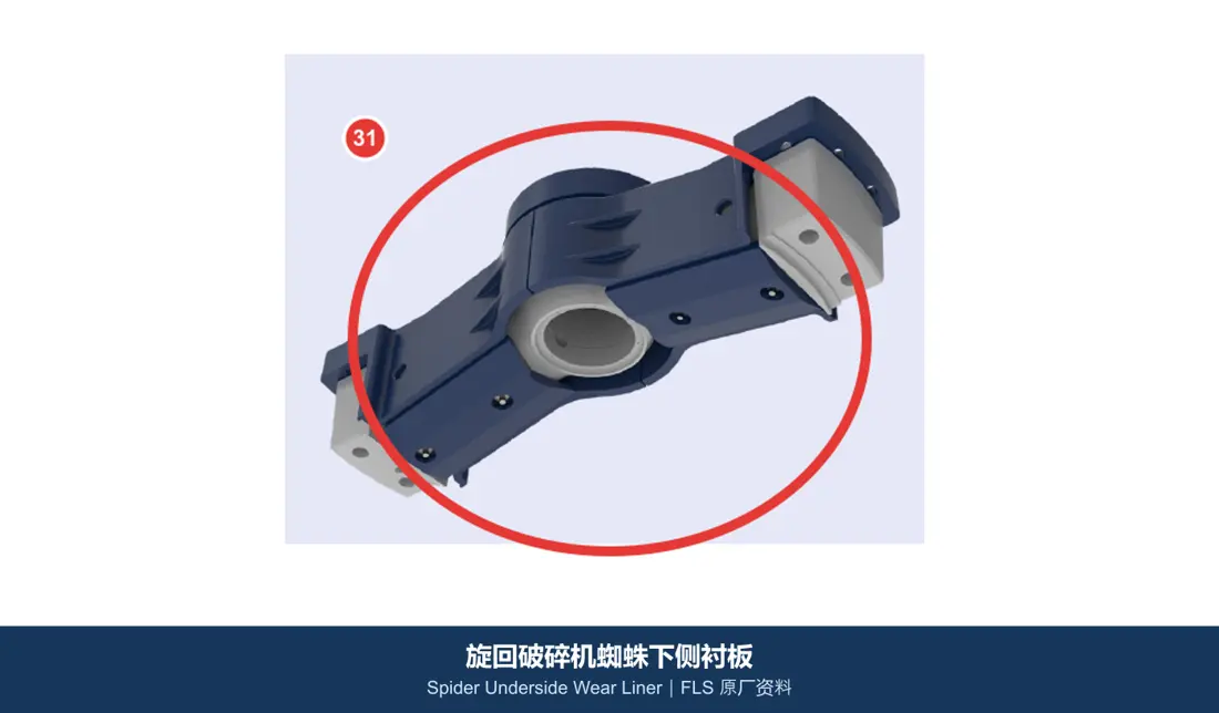
Protect the spider underside and adjacent areas against rock impact, rebound and abrasive flow. Check left/right orientation, plate layout, holes and contact surfaces against the spider.

Material selection: Choose manganese steel or quenched-and-tempered wear plate according to the balance of impact and sliding wear. For welded structures, also check weldability.

View the common part page →
Top shell wear plate identification image
06

Top Shell Wear Plates

Top Shell Wear Plate

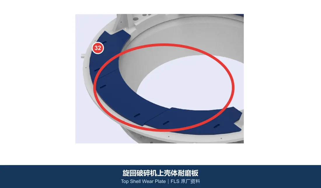
Protect feed and rebound zones in the upper shell. Check installation zones, thickness, curvature, overlaps, fastening and boundaries with the concaves.

Material selection: Confirm quenched-and-tempered wear plate, manganese steel or composite protection against impact, abrasion and mounting method.

View the common part page →
قطع الغيار

Spider, mainshaft, bushings, gears, bearings and hydraulic seals

Identify the mainshaft separately from its protective sleeve. Check drive, load-bearing, bearing and hydraulic sealing parts by series, full model, serial number, drawing revision and mating dimensions.

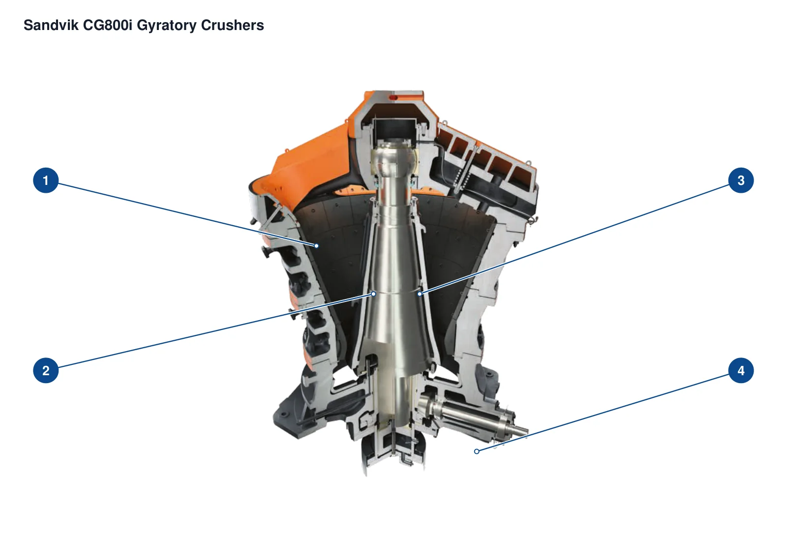
Machine image locating the spider assembly
01

Spider Assembly

Spider Assembly

The machine image locates the upper spider. For the assembly, check arm structure, central support, connecting flanges, lifting points, bushing seat and machine model.

Material selection: Confirm large cast-steel or welded structures, fasteners and support materials against original drawings, loads and nondestructive examination requirements.

View the common part page →
Machine image locating the mainshaft
02

Mainshaft

Mainshaft

The machine image indicates the mainshaft centreline; it is not a photograph of the separate shaft. This critical load-bearing component must be checked separately from its external protective sleeve.

Material selection: Confirm forged alloy steel, heat treatment, journal accuracy, straightness and nondestructive examination against the full model, loads and original drawings.

View the common part page →
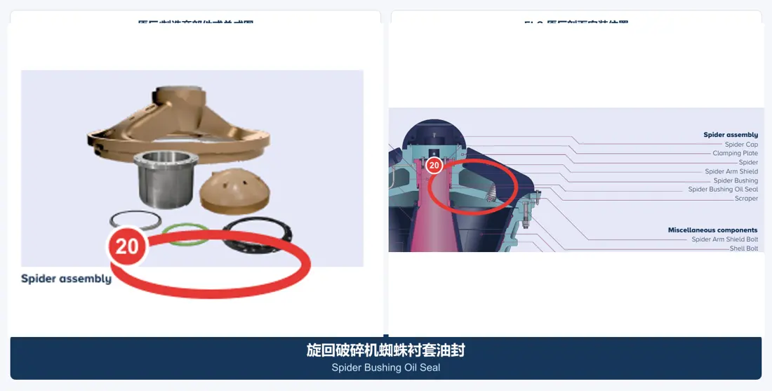
Spider bushing and oil seal identification image
03

Spider Bushing and Oil Seal

Spider Bearing & Oil Seal

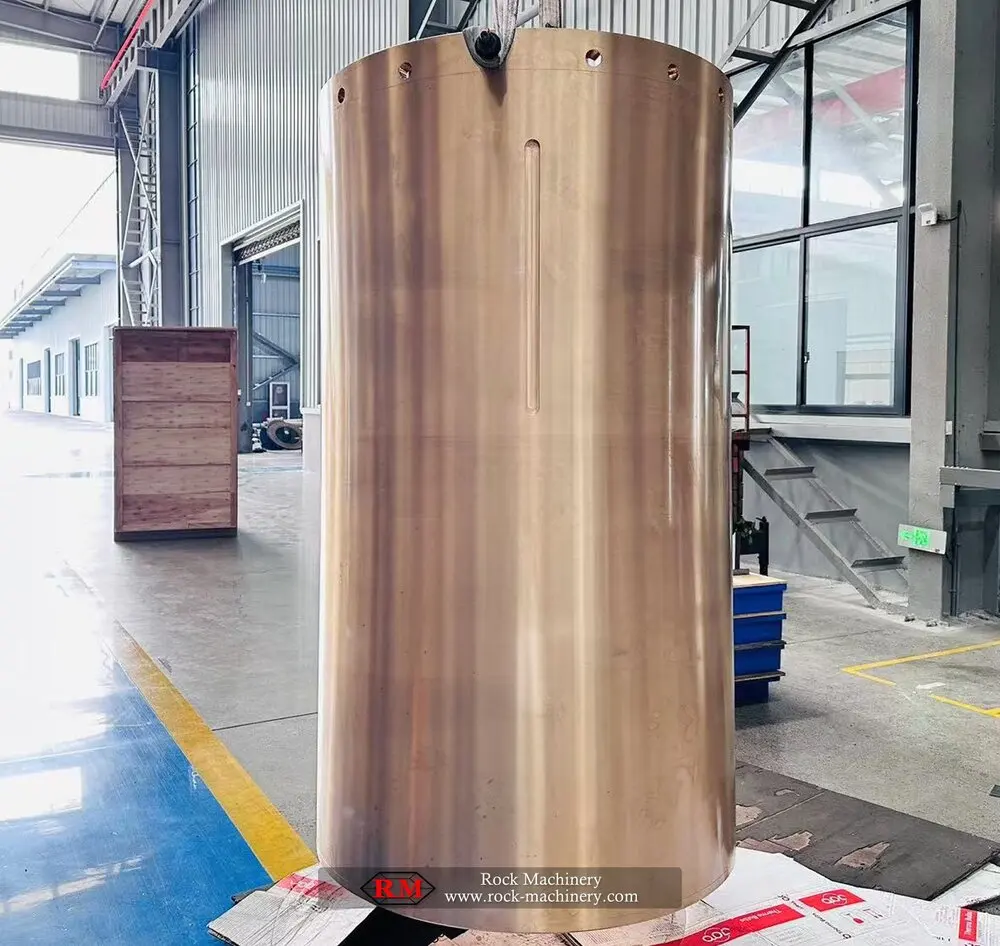
Support the upper mainshaft while retaining lubrication and sealing. Check spherical support geometry, shaft diameter, bushing bore and outside diameter, flange, oil grooves and seal type.

Material selection: Confirm bearing copper alloys, steel support parts and seal materials against loads, lubrication, temperature and fluid.

View the common part page →
Generic gyratory crusher eccentric bushing
04

جلبة لامركزية

جلبة لامركزية

Located within the eccentric mechanism to generate and support mainshaft gyration. Check eccentricity, bore and outside diameter, top/bottom orientation, oil grooves, shoulders and running clearance.

Material selection: Confirm bearing copper-alloy grade, casting quality, oil grooves and fitting clearance against loads, lubrication and original drawings.

View the common part page →
Generic gyratory crusher bevel gear
05

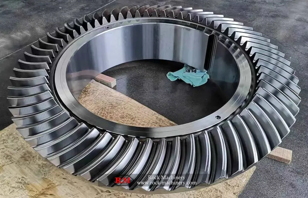
Bevel Gear

Bevel Gear

The image identifies the bevel-gear drive category. Check the gear and pinion as a pair for module, tooth count, pressure angle, spiral direction, mounting distance and contact pattern.

Material selection: Use carburized or quenched-and-tempered transmission alloy steel. Confirm tooth hardness, core toughness, accuracy and paired inspection against the original design.

View the common part page →
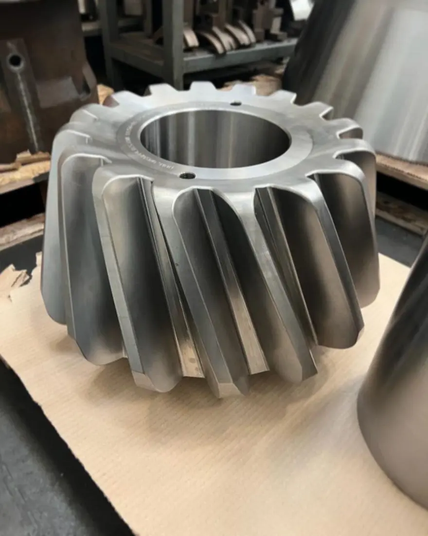
ترس صغير identification image
06

ترس صغير

ترس صغير

Works with the bevel gear to transmit horizontal-shaft power. Check tooth count, spiral direction, tooth geometry, shaft interface, backlash and paired mesh records.

Material selection: Confirm forged transmission alloy steel and heat treatment against torque, impact loads, tooth hardness and core toughness.

View the common part page →
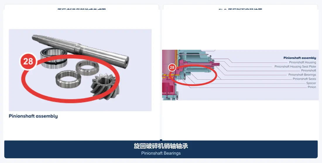
Pinionshaft bearings identification image
07

Pinionshaft Bearings

Pinionshaft Bearings

Support the horizontal pinionshaft and maintain gear centre distance. Check bearing designation, clearance, load direction, journal and housing tolerances and lubrication.

Material selection: Confirm bearing steel, cage and lubricant against speed, load, temperature rise and original bearing specifications.

View the common part page →
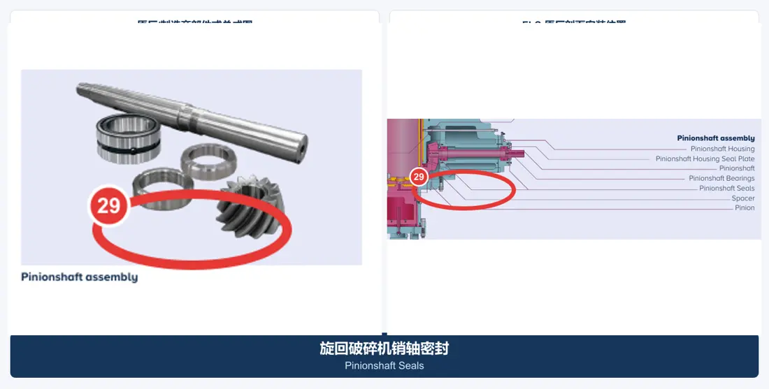
Pinionshaft seals identification image
08

Pinionshaft الموانع

Pinionshaft الموانع

Keep dust out and lubricant in the drive housing. Check shaft diameter, grooves, lip direction, temperature, oil, speed and end-cover geometry.

Material selection: Confirm NBR, HNBR, FKM, polyurethane or other engineering seal materials against temperature, fluid and motion.

View the common part page →
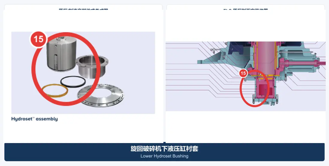
Hydroset bushing identification image
09

Hydroset Bushings

Hydroset Bushings

Used in the hydraulic adjustment and mainshaft support system. Check upper/lower position, diameters, axial height, oil grooves, fitting clearance and hydraulic interfaces.

Material selection: Confirm bearing copper alloys and hydraulic steel components against contact pressure, lubrication, dimensional stability and original drawings.

View the common part page →
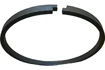
Hydroset piston seal identification image
10

Hydroset Piston Seal

Hydroset Piston Seal

Retains hydraulic adjustment pressure and excludes contamination. Check cylinder and rod diameters, grooves, pressure, temperature, fluid and seal-stack orientation.

Material selection: Confirm polyurethane, NBR, HNBR, FKM, PTFE or composite seals against pressure, fluid and temperature.

View the common part page →
Dust sealing system identification image
11

Dust Sealing System

Dust Sealing System

Protects eccentric and lubrication areas. Check sealing rings, grooves, contact faces, purge or overpressure conditions and associated dust-ring geometry.

Material selection: Confirm elastomers, polyurethane or engineering plastics against dust exposure, temperature, oil and relative motion.

View the common part page →
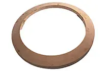
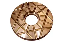
Mainshaft step plates and thrust support identification image
12

Mainshaft Step Plates and Thrust Supports

Step Bearing Components

Carry mainshaft axial loads in conjunction with the hydraulic adjustment system. Check stacking order, contact diameters, oil-film clearance, thrust faces and assembly height.

Material selection: Confirm wear-resistant alloy steel and bearing copper alloys against contact pressure, lubrication, flatness and fit requirements.

View the common part page →
Drawing and Part Numbers

Every number must match a model, installation position and drawing revision

The locally verified records do not yet provide a publicly traceable CG800i-specific parts list, so no numbers are invented here. With complete information, OEM drawing numbers and third-party part numbers are mapped separately to the model, part name, installation position and key dimensions.

Publication policy: Publish only numbers traceable to a model, installation position and original evidence. Record OEM drawing numbers separately from third-party part numbers; do not mix or infer them.

How do names such as CG810, CG820, CG830, CG850 and CG810i relate?

Sandvik's current product cards use CG810, CG820, CG830 and CG850; official technical tables and brochures use CG810i, CG820i, CG830i and CG850i. Enquiries should use the full nameplate designation and serial number.

هل العمود الرئيسي والجلبة الواقية قطعة واحدة؟

No. The mainshaft is a critical load-bearing component; the sleeve is a separate protective part fitted around it. Check drawing numbers, dimensions and materials separately.

Why are unverified CG-specific part numbers not shown?

Part numbers must be traceable to the model, installation position and drawing revision. Without reliable evidence, inferred numbers are not published. Submit an OEM or third-party number for cross-checking.

Submit a Sandvik CG model, drawing number, liner layout or spare-parts request

Provide the full model, serial number, OEM or third-party number, drawings, used-part photos, material and operating conditions. These support part identification, material assessment, manufacturing matching, quality control and finished-part delivery.

Submit التفاصيل for a Quote

رقم الهاتف: +86 156 3797 3199
zzx@anranst.com

خدمات صنع في الصين

من التقييم الفني إلى تسليم المنتج بالكامل

توفر شركة ANRANST للعملاء العالميين تقييمات هندسية، واختيار التصنيع الصيني، ومراقبة الجودة، وتسليم الأجزاء النهائية لقطع الغيار الصناعية المقاومة للتآكل حسب الطلب، ويمكنها أيضًا دعم قطع الغيار الصناعية الأخرى حسب الطلب.

01

مراجعة الرسومات والهندسة

قم بمراجعة أسطح التزاوج وأبعاد الواجهة، وقم بتقييم جدوى المواد والمعالجة الحرارية والتصنيع.

02

تحديد المادة والمعالجة الحرارية

تُحدَّد درجات المواد وعمليات المعالجة الحرارية لكل طلب على حدة، وتُثبَّت في الاتفاقية الفنية وتُتابَع أثناء الإنتاج.

03

ضبط الجودة

يشمل ذلك تأكيد الرسم، ومراقبة المواد والعمليات، وتتبع الإنتاج، وتنسيق عمليات الفحص والقبول.

04

تسليم المنتج النهائي

تنظيم عمليات التصنيع والتحقق من الجودة والتعبئة والتغليف وتسليم المنتجات النهائية الكاملة لتشكيل حلقة إمداد قابلة للتنفيذ.

قم بتزويدنا بالنماذج الحالية، والرسومات، وأرقام الرسومات، وأرقام الأجزاء، والمواد، أو معلومات ظروف التشغيل، وسنقوم بتحديد التحقق الفني ومسار التوريد وفقًا لذلك.

إرسال طلب