
01
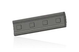
قضبان الصدم
قضيب الصدم
تركب على الدوار تحت الصدم المباشر عالي السرعة. طابق المقطع والطول والوزن وبنية القفل ومجرى الدوار واتجاه سطح العمل وشرائط الإسناد.
عرض صفحة المكون →استخدم الطرازات الحالية CI711–CI732 لتحديد قضبان الصدم وألواح الصدم والدوارات والمحامل ومجموعات الصدم وقطع الضبط الهيدروليكي والمواد للتسعير.
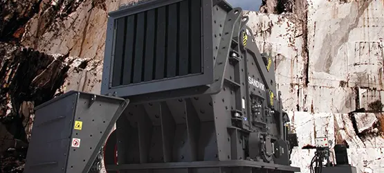
تحدد الطرازات والمواصفات الرئيسية المعدة. ترتبط قطع التآكل وقطع الغيار العامة بصفحات المكونات والمواد. تترك الرسومات فارغة عند غياب مطابقة موثوقة.
يؤخذ الوزن والحجم الأقصى للتغذية والإنتاجية والقدرة من صفحات Sandvik الحالية لHSI الثابتة، وتساعد في التحديد الأولي.
| Model | Weight | التغذية القصوى | Capacity | قدرة المحرك |
|---|---|---|---|---|
| CI732 | 29,650 kg | 350 mm | 250–575 t/h | 440 kW |
| CI731 | 27,750 kg | 1,000 mm | 400–700 t/h | 440 kW |
| CI722 | 16,256 kg | 350 mm | 150–250 t/h | 250 kW |
| CI721 | 16,000 kg | 900 mm | 200–400 t/h | 250 kW |
| CI712 | 11,184 kg | 300 mm | ≤150 t/h | 185 kW |
| CI711 | 11,005 kg | 600 mm | ≤200 t/h | 185 kW |
تتطابق الأرقام على المخطط مع الصفوف أدناه.
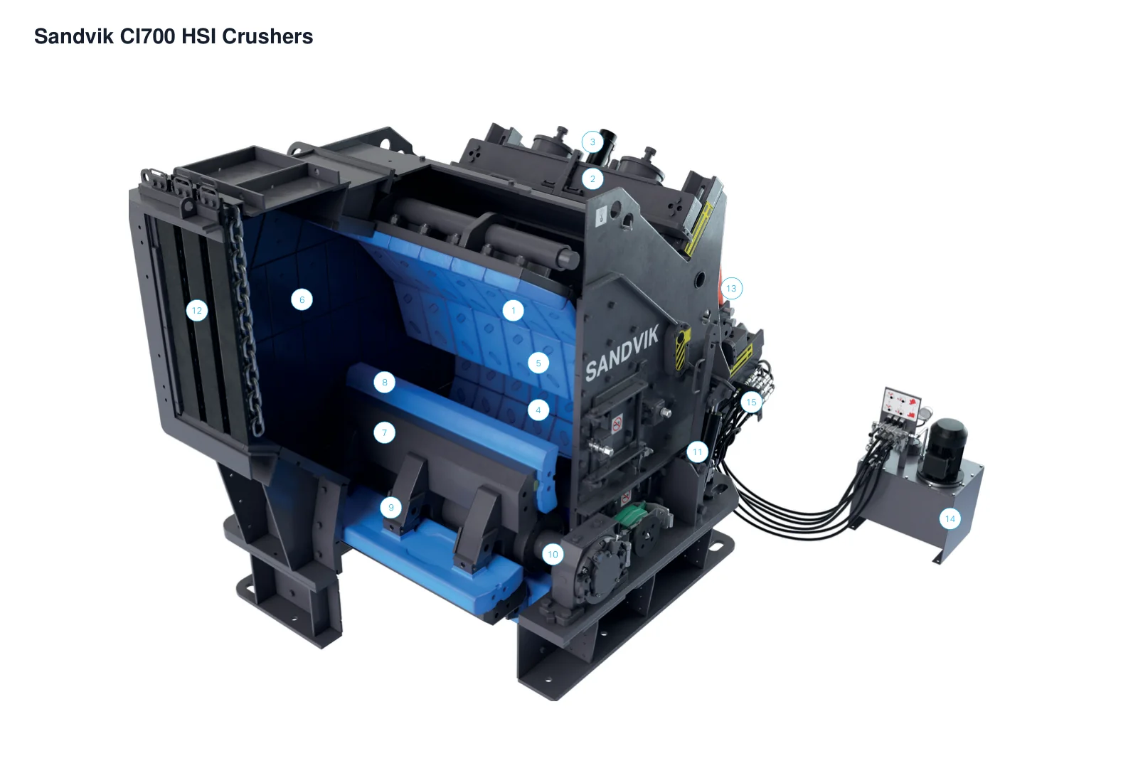
| الرقم | المكوّن | الموضع | ينطبق على |
|---|---|---|---|
| 1 | لوح الصدم الأول | لوح الصدم في مرحلة التكسير الأولى | CI700 - صورة عائلة OEM (الأبعاد غير محددة) |
| 2 | العارضة العرضية للوح الصدم الأول | عارضة عرضية فوق لوح الصدم الأول | CI700 - صورة عائلة OEM (الأبعاد غير محددة) |
| 3 | أسطوانة ضبط لوح الصدم الأول | آلية الضبط فوق لوح الصدم الأول | CI700 - صورة عائلة OEM (الأبعاد غير محددة) |
| 4 | لوح الصدم الثاني | مرحلة التكسير الصدمي الثانية | CI700 - صورة عائلة OEM (الأبعاد غير محددة) |
| 5 | بطانات ألواح الصدم | أسطح عمل ألواح الصدم | CI700 - صورة عائلة OEM (الأبعاد غير محددة) |
| 6 | بطانات الهيكل | الجدران الداخلية لهيكل حجرة التكسير | CI700 - صورة عائلة OEM (الأبعاد غير محددة) |
| 7 | Rotor | حجرة التكسير السفلية | CI700 - صورة عائلة OEM (الأبعاد غير محددة) |
| 8 | مطرقة / قضيب الصدم | محيط الدوار | CI700 - صورة عائلة OEM (الأبعاد غير محددة) |
| 9 | إسفين قفل المطرقة | وصلة المطرقة بالدوار | CI700 - صورة عائلة OEM (الأبعاد غير محددة) |
| 10 | غلاف المحمل | الطرف الخارجي لعمود الدوار | CI700 - صورة عائلة OEM (الأبعاد غير محددة) |
| 11 | أسطوانة الهيكل المحوري | وصلة فتح الهيكل الخلفي | CI700 - صورة عائلة OEM (الأبعاد غير محددة) |
| 12 | قادوس التغذية الأولي | المدخل العلوي | CI700 - صورة عائلة OEM (الأبعاد غير محددة) |
| 13 | ذراع رفع المطارق | موضع الرفع فوق الهيكل | CI700 - صورة عائلة OEM (الأبعاد غير محددة) |
| 14 | وحدة قدرة هيدروليكية كهربائية | وحدة منفصلة على اليمين | CI700 - صورة عائلة OEM (الأبعاد غير محددة) |
| 15 | وصلات هيدروليكية سريعة الفصل | وصلة خارجية لوحدة القدرة الهيدروليكية | CI700 - صورة عائلة OEM (الأبعاد غير محددة) |
حدد كل موضع منفصلا. اختر المواد بحسب الصدمات والكشط ووجود المعادن في التغذية وشكل الجسيمات المطلوب والوصول للاستبدال وأنماط الأعطال الحالية.
قضيب الصدم
تركب على الدوار تحت الصدم المباشر عالي السرعة. طابق المقطع والطول والوزن وبنية القفل ومجرى الدوار واتجاه سطح العمل وشرائط الإسناد.
عرض صفحة المكون →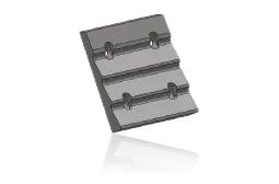
بطانة لوح الصدم الأول
تتحمل صدمات وكشطا أشد في المرحلة الأولى. طابق تسلسل الأجزاء والتقوس والثقوب والسماكة والتراكب وموضع لوح الصدم.
عرض صفحة المكون →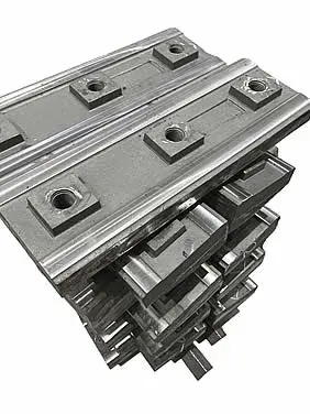
بطانة لوح الصدم الثاني
تضبط الشكل وتواصل تصغير الحجم. طابق موضع الصف والتقوس والثقوب والسماكة وخلوص العمل مع الدوار.
عرض صفحة المكون →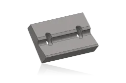
بطانة لوح الصدم الثالث
للمعدات المزودة بمرحلة صدم ثالثة. طابق التكوين والموضع وعدد الأجزاء والثقوب والتقوس وفتحة التفريغ.
عرض صفحة المكون →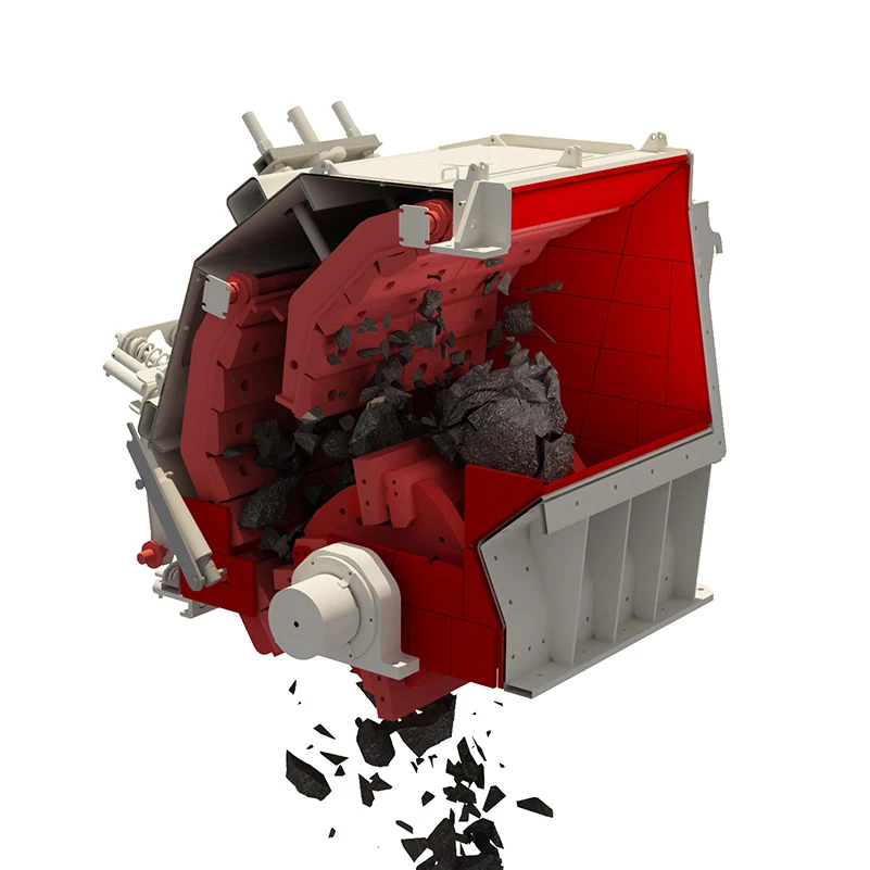
بطانة جانبية
تحمي جانبي الهيكل من احتكاك الخام. طابق الجانب والموضع الأمامي/الخلفي ومرجع الجزء والثقوب والسماكة والخلوص مع لوح الصدم.
عرض صفحة المكون →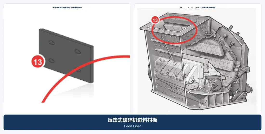
بطانة التغذية
تحمي مسار التغذية ومدخل الحجرة. طابق ترتيب الأجزاء واتجاه التغذية والثقوب والسماكة والتراكب والخلوص الآمن مع مسار الدوار.
عرض صفحة المكون →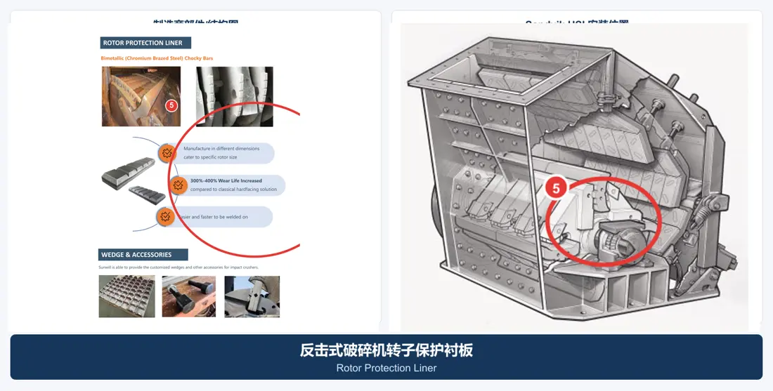
بطانة حماية الدوار
تحمي الدوار ومنطقة تركيب قضبان الصدم. طابق الموضع والشكل والثقوب والمثبتات وتوازن الوزن وواجهات مجموعة القضيب.
عرض صفحة المكون →طابق قطع الإدارة والدعم والقفل والهيدروليك بحسب الطراز الكامل والاتجاه والأبعاد الرئيسية والتوافقات والتفاوتات والضغط وعلاقات المجموعات.
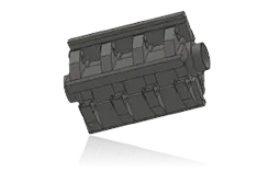
مجموعة الدوار
المجموعة الدوارة الرئيسية عالية السرعة للكسارة. طابق الطراز الكامل والقطر والعرض ومجاري القضبان ونهايات العمود والدوران والقصور الذاتي واللحام والتوازن.
عرض صفحة المكون →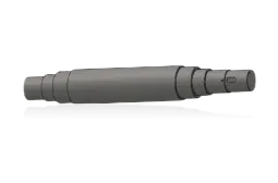
عمود الدوار
ينقل قدرة المحرك ويدعم الدوار. طابق القطر ومقاعد المحامل ومجاري المفاتيح والنهايات والدوران والمادة والمعالجة الحرارية والانحراف والفحص غير الإتلافي.
عرض صفحة المكون →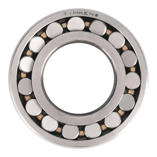
محمل الدوار
تتحمل الأحمال الشعاعية والصدمات وارتفاع الحرارة. طابق التسمية الكاملة والخلوص والتوافقات والتفاوتات والتزييت والأختام ومراقبة الحرارة.
عرض صفحة المكون →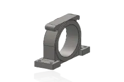
مبيت المحمل
تحدد مواضع المحامل وتدعمها. طابق الجانب وارتفاع المركز وثقوب التركيب والمحامل والتفاوتات وممرات الزيت وواجهات الأختام ومراجع الهيكل.
عرض صفحة المكون →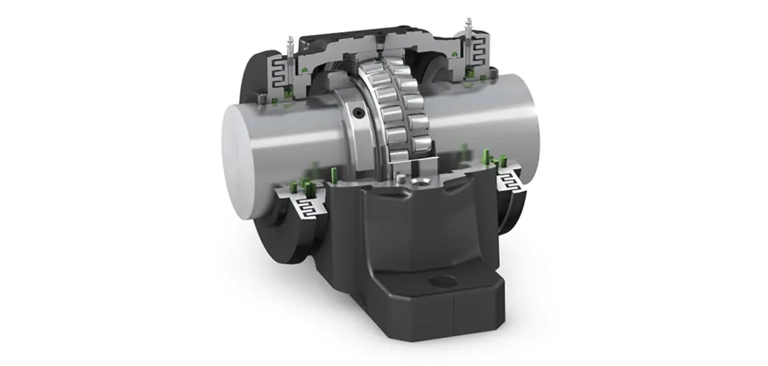
مانع تسرب محمل الدوار
تمنع دخول الغبار وتحفظ مادة التزييت. طابق تصميم الختم وقطر العمود والاتجاه والخلوص والحرارة ومادة التزييت وواجهة غطاء النهاية.
عرض صفحة المكون →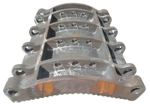
مجموعة لوح الصدم
تدعم البطانات وتشكل فتحة التكسير. طابق المرحلة الأولى/الثانية/الثالثة ومحور الارتكاز والدعامات والواجهات الهيدروليكية وترتيب البطانات وزاوية العمل.
عرض صفحة المكون →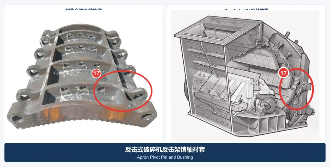
محور مفصل لوح الصدم & جلبته
تدعم حركة لوح الصدم وضبطه. طابق قطر المحور وطوله وأقطار الجلبة وأخاديد الزيت والتثبيت والتوافقات والاتجاه.
عرض صفحة المكون →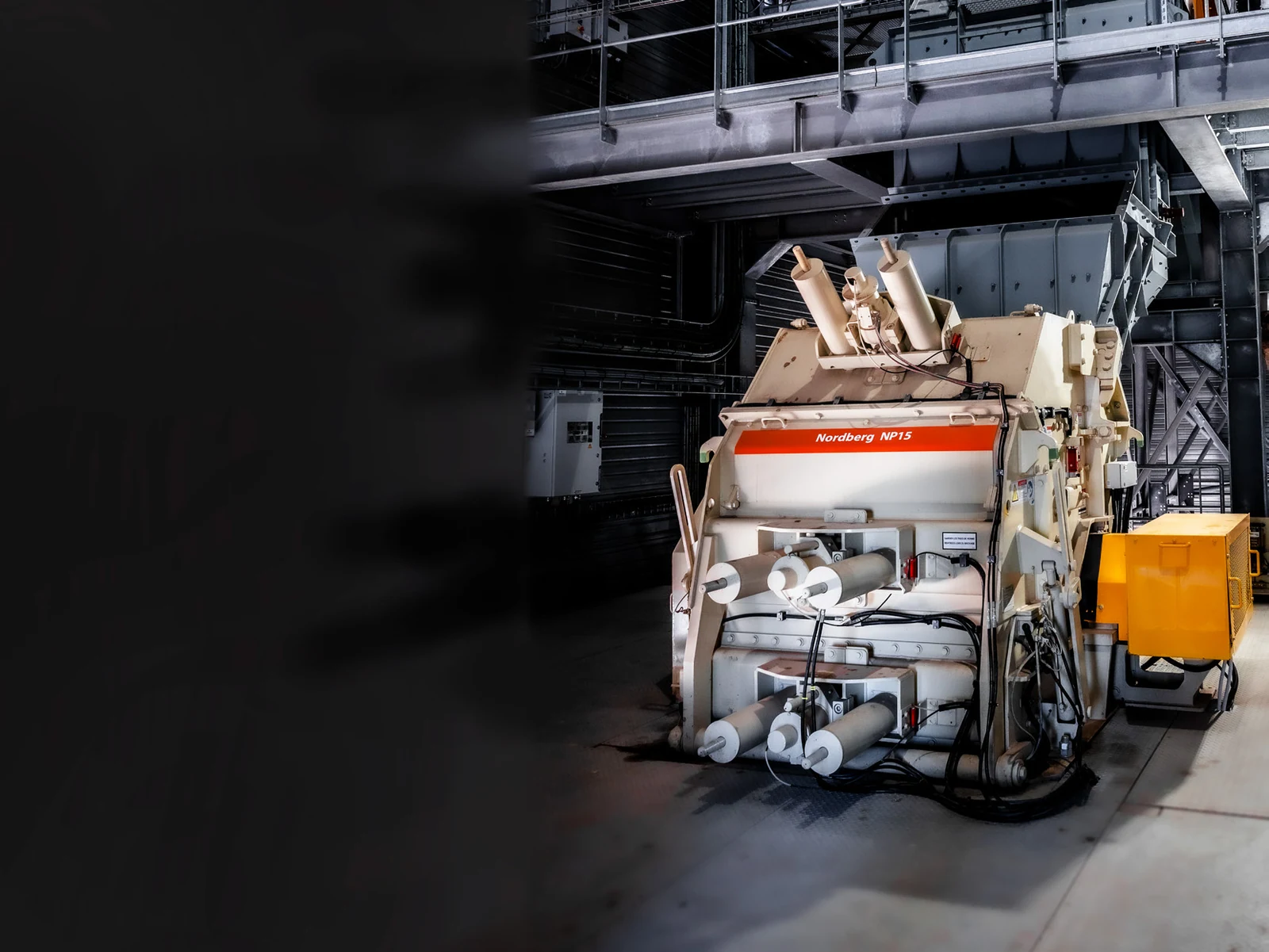
أسطوانة ضبط اللوح الصدمي
تضبط فتحة التكسير وتحرك لوح الصدم. طابق قطر الأسطوانة والقضيب والشوط ومحاور الدوران والمنافذ والضغط والأختام والجانب.
عرض صفحة المكون →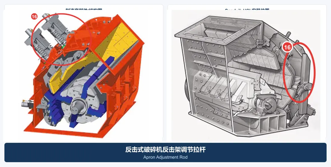
قضيب ضبط لوح الصدم
تربط نظام الضبط وتنقل التحميل المسبق أو أحمال تحديد الموضع. طابق الطول واللولب والقطر والنهايات والنوابض والموضع.
عرض صفحة المكون →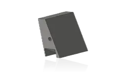
إسفين إمساك قضيب الصدم
تقفل القضبان في مجاري الدوار. طابق الزاوية والطول والاتجاه وأسطح التلامس والتثبيت وشرائط الإسناد والقضبان المتوافقة.
عرض صفحة المكون →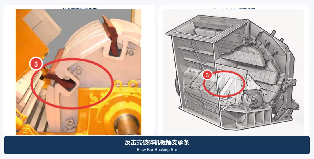
قضيب إسناد قضيب الصدم
تركب بين القضيب ونظام قفل الدوار. طابق المقطع والطول والأسطح والاتجاه ومجموعة القضيب/الإسفين المتوافقة.
عرض صفحة المكون →لا. طابق مجرى الدوار ومقطع القضيب وطوله ووزنه وقفله واتجاه عمله ومادته وشرائط الإسناد أو الأسافين المتوافقة.
ليس بالضرورة. يؤثر حجم التغذية وطاقة الصدم والكشط وسرعة الدوار ومراحل الصدم والفتحات في القضبان والبطانات.
نعم. أرسل الطراز الكامل والرقم التسلسلي والموضع والصور والأبعاد الرئيسية أو الرسومات. نحدد القطعة قبل الاتفاق على التوريد.
قدم الطراز الكامل والرقم التسلسلي والموضع والرسومات أو العينات والصور والمادة وظروف العمل لتحديد القطعة وتقييم المادة ومراقبة الجودة والتسليم.
أو تواصل معنا مباشرة: +86 156 3797 3199
zzx@anranst.com
تقدّم ANRANST لعملائها حول العالم التقييم الهندسي والإنتاج في مسابك معتمدة وفق المتطلبات الفنية للعميل ومراقبة الجودة وتسليم القطع الجاهزة لقطع التآكل المخصّصة وقطع الغيار الصناعية، مع إمكانية دعم قطع صناعية مخصّصة أخرى.
نراجع أسطح التزاوج وأبعاد الوصلات، ونقيّم إمكانية التصنيع من حيث المادة والمعالجة الحرارية.
Material grades and heat-treatment processes are specified order by order, stated in the technical agreement and tracked through production.
تأكيد الرسم، ومراقبة المواد والعمليات، ومتابعة الإنتاج، والفحص، وتنسيق القبول.
ننسّق التصنيع وتأكيد الجودة والتغليف والتسليم للقطع الكاملة ضمن سلسلة توريد متكاملة وعملية.
زوّدنا بالطراز الحالي والرسومات والمواد أو ظروف التشغيل لنتمكن من تحديد المراجعة الفنية ومسار التوريد المناسبين.
أرسل استفساراً