
01
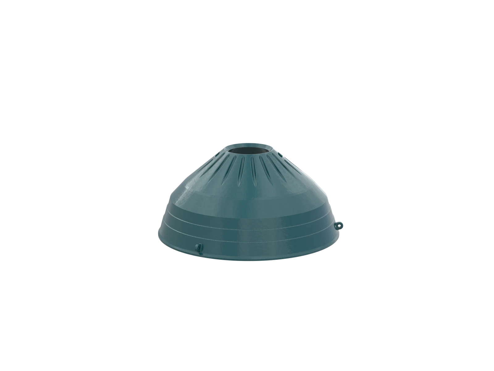
Mantle
Mantle / Head Liner
Mounted on the head and moving eccentrically to form the crushing chamber with the concave. Check chamber, profile, head interface, backing clearance, setting and wear zones.
View the common part page →Start with CH, CS and 800i standard models to identify mantles, concaves, frame wear parts, copper-alloy bushings, drives, hydraulics and known references for an enquiry.
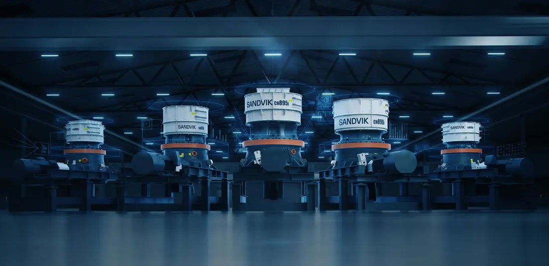
This page retains current standard models, key dimensions, positions, materials and reference checks directly relevant to spare-part supply. Legacy H/S mappings require separate confirmation from a nameplate or equipment documents.
Maximum feed, nominal capacity and motor power follow Sandvik stationary cone crusher pages and model data. Confirm final values against chamber, eccentric throw, setting and project configuration.
| Model | Maximum feed size | Nominal capacity | Motor power |
|---|---|---|---|
| CH895i | 127 mm | 258–1,077 t/h | 750 kW |
| CH890i | 428 mm | 275–1,837 t/h | 750 kW |
| CH870i | 350 mm | 202–1,370 t/h | 600 kW |
| CH865i | 123 mm | 155–517 t/h | 500 kW |
| CH860i | 315 mm | 250–910 t/h | 500 kW |
| CH840i | 250 mm | 212–659 t/h | 330 kW |
| CH830i | 211 mm | 61–283 t/h | 250 kW |
| CS840i | 431 mm | 212–659 t/h | 330 kW |
| CH662 | 286 mm | 116–646 t/h | 315 kW |
| CH660 | 321 mm | 116–646 t/h | 315 kW |
| CH442 | 250 mm | 58–336 t/h | 220 kW |
| CH440 | 250 mm | 58–336 t/h | 220 kW |
| CH430 | 214 mm | 42–215 t/h | 132 kW |
| CH420 | 155 mm | 21–135 t/h | 90 kW |
| CS660 | 622 mm | 314–908 t/h | 315 kW |
| CS440 | 500 mm | 191–510 t/h | 220 kW |
| CS430 | 400 mm | 99–298 t/h | 132 kW |
| CS420 | 267 mm | 70–172 t/h | 90 kW |
The numbers on the diagram correspond one to one with the rows below.
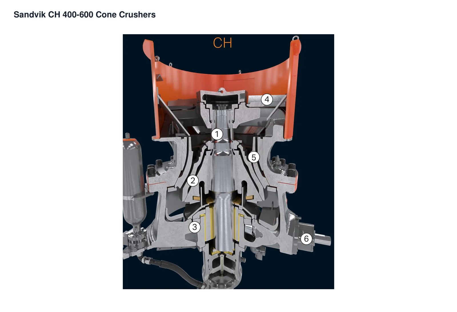
| No. | Component | Location | Applies to |
|---|---|---|---|
| 1 | Main shaft sleeve and inner head nut | Upper main-shaft protection and locking | CH420/CH430/CH440/CH660 OEM family section (dimensions not specified) |
| 1 | Feed opening | Large upper feed opening | CS420/CS430/CS440/CS660 OEM family section (dimensions not specified) |
| 2 | Crushing liners | Opposing mantle and concave working faces | CH420/CH430/CH440/CH660 OEM family section (dimensions not specified) |
| 2 | Crushing chamber | Crushing area between the liners | CS420/CS430/CS440/CS660 OEM family section (dimensions not specified) |
| 3 | Bevel gears | Lower drive engagement | CH420/CH430/CH440/CH660 OEM family section (dimensions not specified) |
| 3 | Bottom shell | Lower frame with a shared CH/CS design | CS420/CS430/CS440/CS660 OEM family section (dimensions not specified) |
| 4 | Top-shell arms | Top-shell supports beside the feed opening | CH420/CH430/CH440/CH660 OEM family section (dimensions not specified) |
| 4 | Crushing liners | Opposing mantle and concave working faces | CS420/CS430/CS440/CS660 OEM family section (dimensions not specified) |
| 5 | Crushing chamber | Chamber between mantle and concave | CH420/CH430/CH440/CH660 OEM family section (dimensions not specified) |
| 5 | Crushing chamber profile | OEM CCP chamber-profile location | CS420/CS430/CS440/CS660 OEM family section (dimensions not specified) |
| 6 | Pinion shaft assembly | Lateral drive shaft and its bearings | CH420/CH430/CH440/CH660 OEM family section (dimensions not specified) |
| 6 | Pinion shaft assembly | Lower lateral shaft housing | CS420/CS430/CS440/CS660 OEM family section (dimensions not specified) |
Mantles and concaves are followed by feed, mainframe and arm protection parts. Cards link each position to common-part and material information.
Mantle / Head Liner
Mounted on the head and moving eccentrically to form the crushing chamber with the concave. Check chamber, profile, head interface, backing clearance, setting and wear zones.
View the common part page →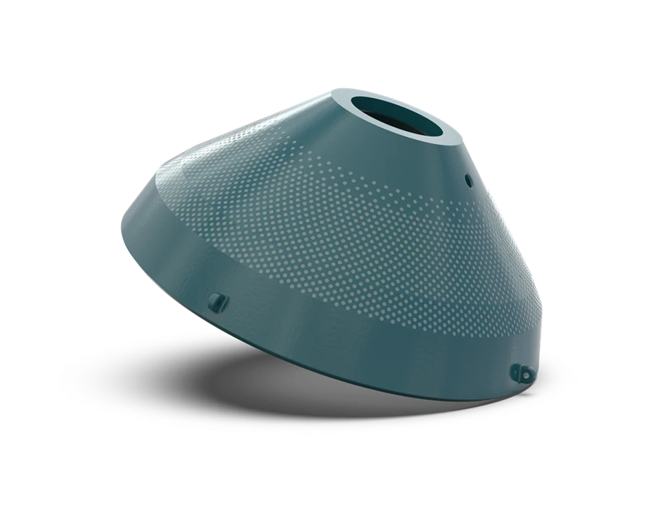
Concave / Bowl Liner
Fixed in the upper shell or adjustment ring to form the specified chamber with the mantle. Check chamber, angle, support face, locking, closed-side setting and wear profile.
View the common part page →
Feed Plate / Feed Cone
At the crusher top, distribute ore and protect the head. Check outside diameter, center bore, conical surface, fastening, rotation and feed impact point.
View the common part page →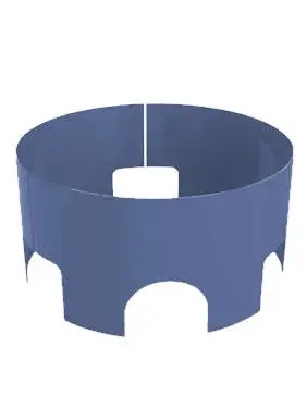
Main Frame Liner
Protect frame areas exposed to falling material, rebound and dust erosion. Check sections, curvature, openings, thickness, holes and drive-side clearance.
View the common part page →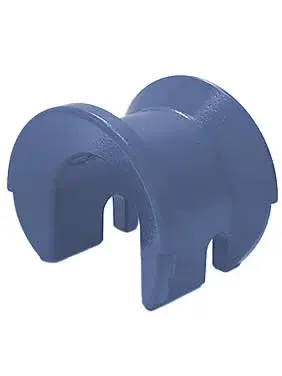
Arm Guard / Arm Liner
Protect frame arms and discharge areas from flying-rock impact and material friction. Check arm position, left/right orientation, holes, mating face and removal access.
View the common part page →Identify drive and support parts separately. Check complete model, serial number, drawing revision, orientation, fits, gear parameters and hydraulic interfaces.
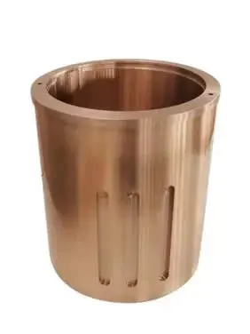
Eccentric Bushing
Installed in the eccentric mechanism to support mainshaft movement. Check inside/outside diameters, eccentricity, upper/lower orientation, oil grooves, shoulders and working clearance.
View the common part page →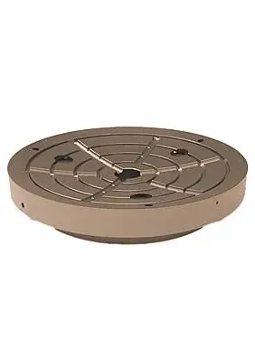
Socket Liner
Carries the head load through spherical support. Check spherical radius, thickness, oil grooves, contact pattern, shoulders and lubrication passages.
View the common part page →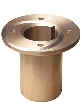
Countershaft Bushing
Supports the horizontal drive shaft and maintains gear center distance. Check flange orientation, diameters, keyway, oil holes, axial location and clearance.
View the common part page →Drive Gear
The official machine image identifies the equipment category, not an individual gear. Check the gear and pinion together for module, tooth count, hand, mounting distance, backlash and contact pattern.
View the common part page →Pinion & Countershaft
The official machine image identifies the equipment category, not an individual part. Check tooth form, shaft diameter, bearing seats, rotation, end connections and drive-housing construction.
View the common part page →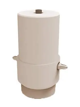
Clamping Cylinder Assembly
Clamps or holds the adjustment system. Check bore, stroke, pressure, mounting trunnions, oil ports, seal grooves and control logic.
View the common part page →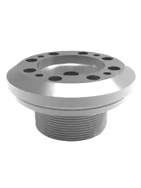
Locking Nut
Secures the mantle or associated head structure. Check thread, hand, end face, holes, locking method and installation-tool interfaces.
View the common part page →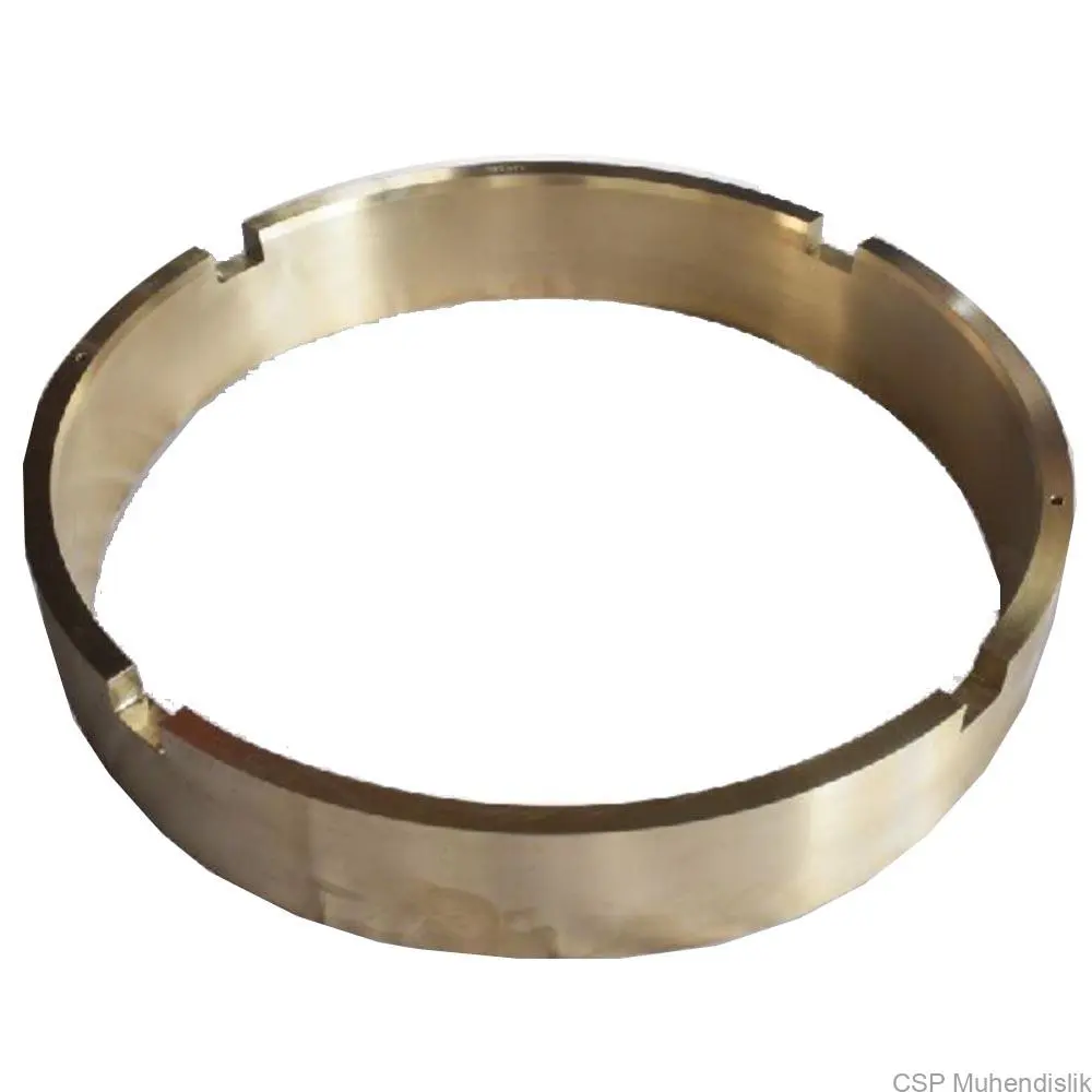
Upper Head Bushing
The image identifies a copper-alloy bushing category. Check upper position, inside/outside diameters, length, oil grooves, locating shoulders and mainshaft fit.
View the common part page →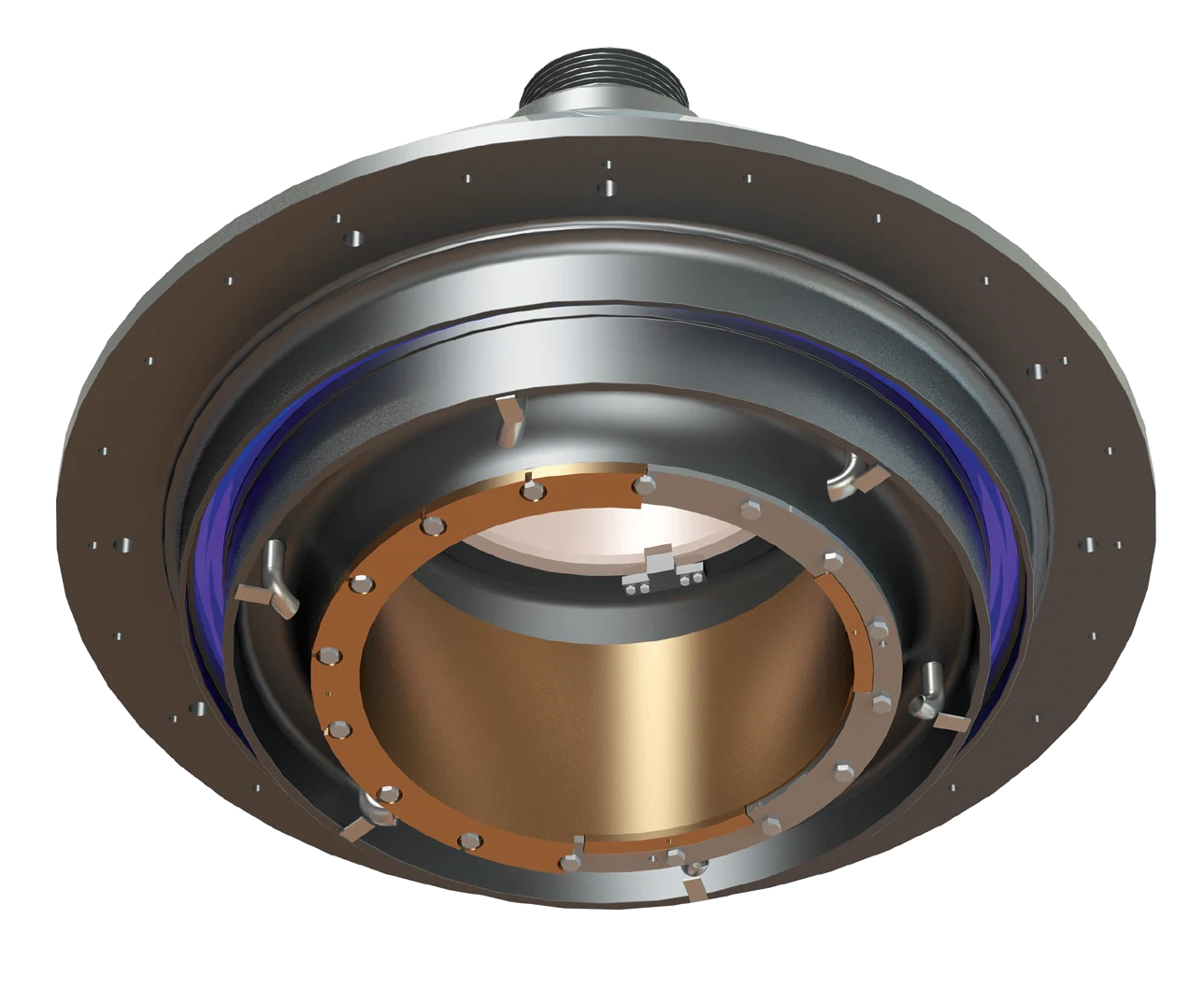
Lower Head Bushing
The image identifies a copper-alloy bushing category. Check lower position, inside/outside diameters, length, oil grooves, locating shoulders and working clearance.
View the common part page →No. Even similar model numbers require checks of complete model, chamber, serial number, drawings, orientation, interfaces and fits.
No. They are explicitly identified as third-party evidence for preliminary searching only. Verify nameplate, BOM, drawing revision and position before manufacture.
No. Also consider chamber, feed, impact, ore hardness, wear zones, casting and heat-treatment quality, and the site's service-life target.
Provide complete model, serial number, drawings or samples, used-part photographs, materials and conditions. We use these for identification, material assessment, manufacturing matching, quality control and delivery.
Or contact us directly: +86 156 3797 3199
zzx@anranst.com
ANRANST provides customers worldwide with engineering assessment, production at certified foundries to the customer technical requirements, quality control and finished-part delivery for custom wear parts and industrial spares, with scope to support other custom industrial parts.
We review mating surfaces and interface dimensions and assess material, heat treatment and manufacturing feasibility.
Material grades and heat-treatment processes are specified order by order, stated in the technical agreement and tracked through production.
Drawing confirmation, material and process control, production tracking, inspection and acceptance coordination.
We coordinate manufacturing, quality confirmation, packaging and delivery of complete finished parts in a workable, closed-loop supply process.
Provide the existing model, drawings, drawing, materials or operating conditions so we can identify the appropriate technical review and supply route.
Submit an Enquiry