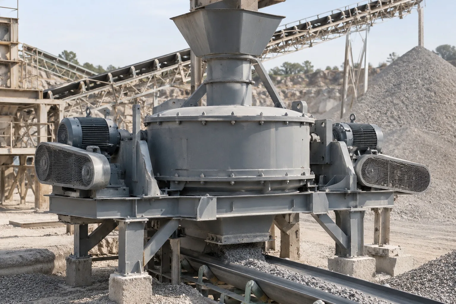
VSI crushers use a high-speed vertical rotor to accelerate material against fixed anvils or an autogenous rock bed. Impact, splitting, abrasion and particle collisions produce fine crushing and shaping. Wear life depends on more than part hardness: feed size, abrasiveness, moisture, rotor tip speed, cascade feed ratio, rock-bed shape and uncrushable material all affect performance.
Equipment Parts
Part Identification and Technical Details
Explore part names, images, material options and technical requirements. Select a card to open the corresponding replacement part page.
Individual parts
Individual and Maintenance Parts
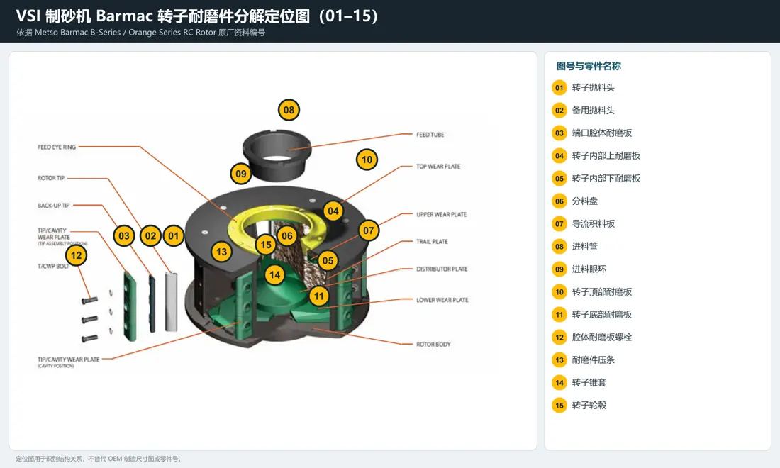
01
Rotor Tip Set
- Equipment Configuration
- Barmac / Enclosed Rotor
- Installation and Function
- Outermost edge of each rotor discharge port
- Material Options
- WC-Co Cemented Carbide with a High-Strength Steel / Wear-Resistant Cast Steel Support Body
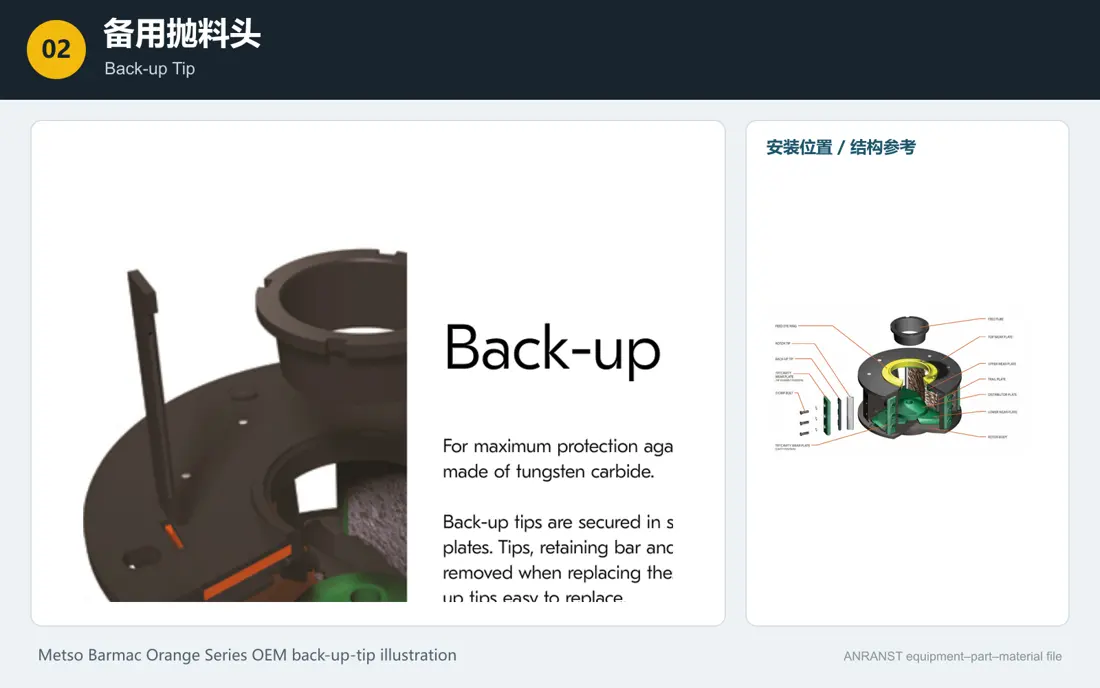
02
Back-up Tip
- Equipment Configuration
- Barmac / Enclosed Rotor
- Installation and Function
- Behind the main rotor tip
- Material Options
- Wear-Resistant Cast Steel / High-Strength Steel with WC Inserts
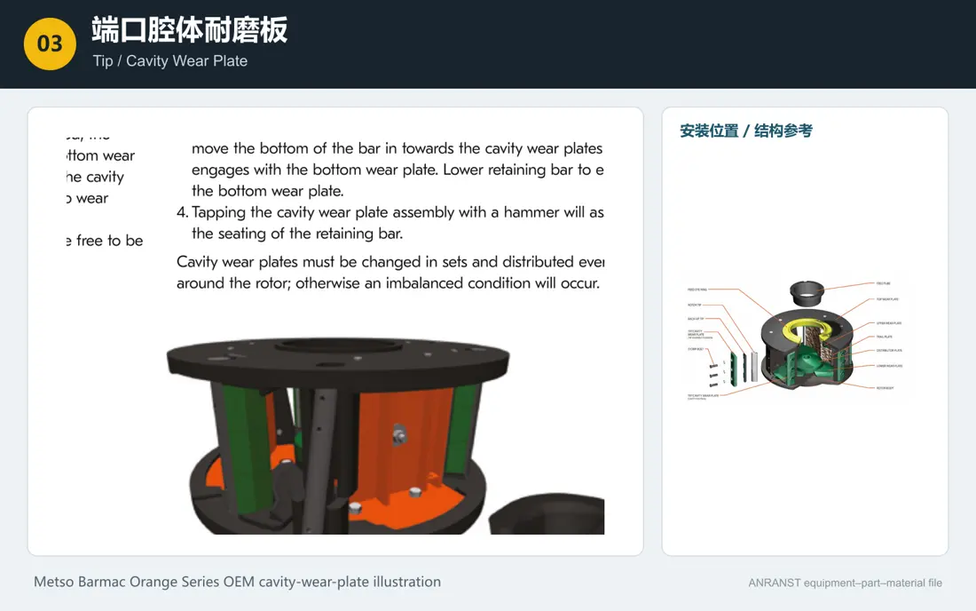
03
Tip / Cavity Wear Plate
- Equipment Configuration
- Barmac / Enclosed Rotor
- Installation and Function
- Leading edge of the discharge port and the area next to the rotor tip
- Material Options
- High-Chromium White Cast Iron / Martensitic Wear-Resistant Steel / OEM Wear-Resistant Castings
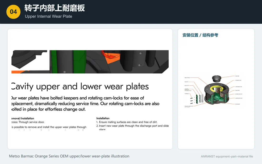
04
Upper Internal Wear Plate
- Equipment Configuration
- Barmac / Enclosed Rotor
- Installation and Function
- Upper level inside the rotor
- Material Options
- High-Chromium White Cast Iron / Martensitic Wear-Resistant Cast Steel
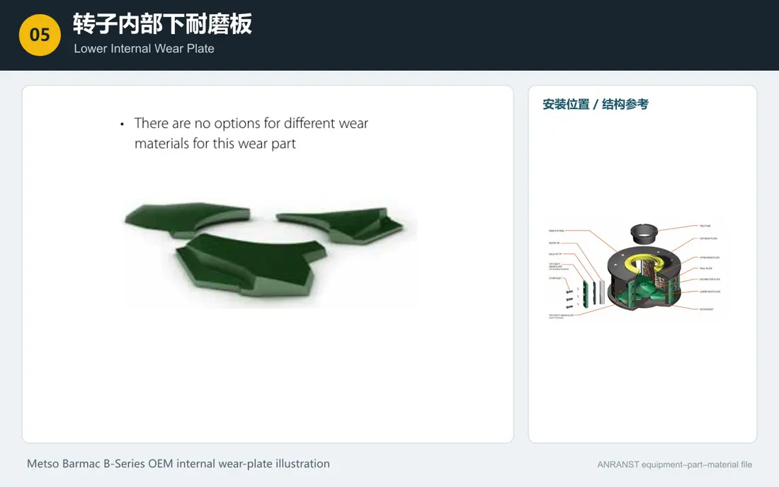
05
Lower Internal Wear Plate
- Equipment Configuration
- Barmac / Enclosed Rotor
- Installation and Function
- Lower level inside the rotor
- Material Options
- High-Chromium White Cast Iron / Martensitic Wear-Resistant Cast Steel
06
Distributor Plate
- Equipment Configuration
- Enclosed Rotor Designs
- Installation and Function
- At the rotor center, above the main shaft
- Material Options
- High-Chromium White Cast Iron / Wear-Resistant Cast Steel / WC Cap / MMC
07
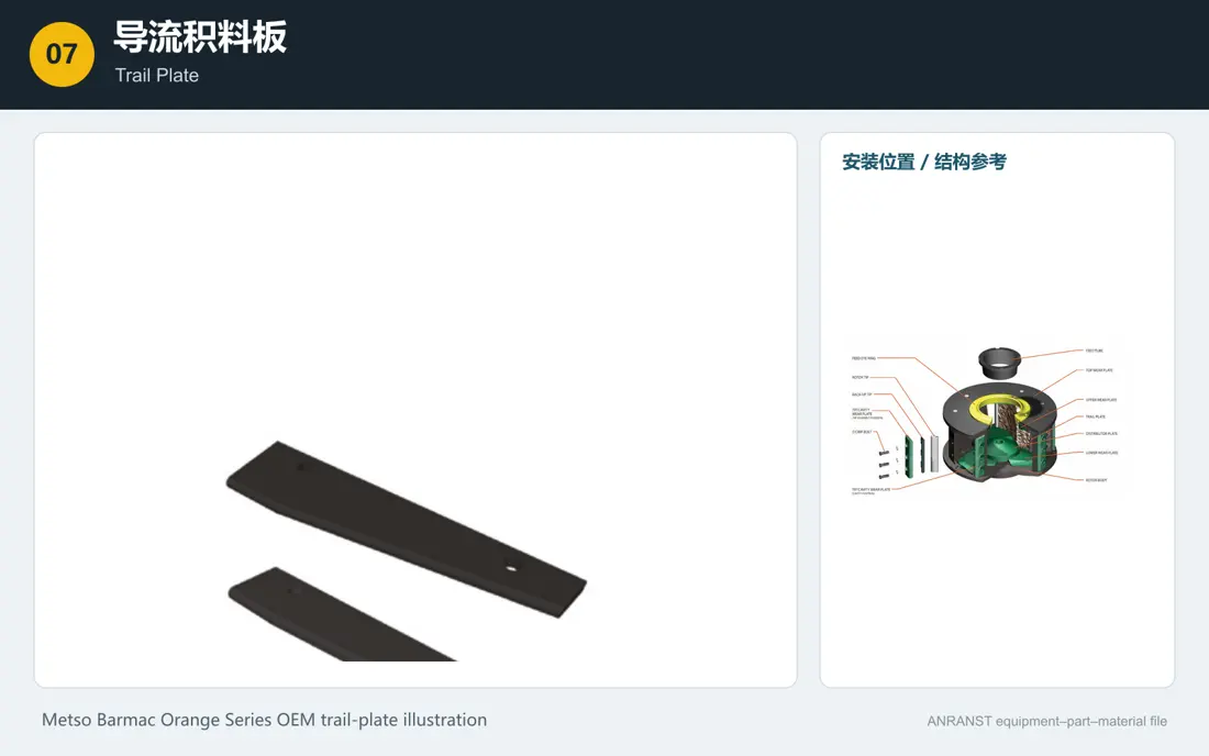
Trail Plate
- Equipment Configuration
- Barmac / Enclosed Rotor
- Installation and Function
- Inner trailing edge of each rotor port
- Material Options
- Wear-Resistant Steel / Martensitic Steel / Hardfaced or WC Edge
08
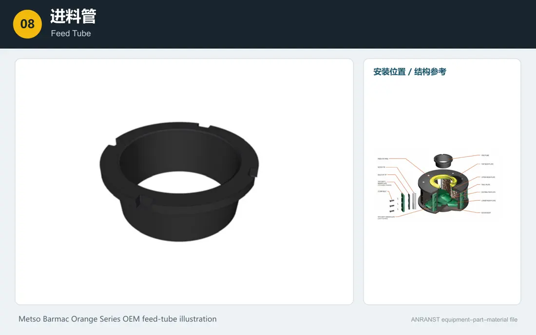
Feed Tube
- Equipment Configuration
- Common to Multiple Designs
- Installation and Function
- Below the hopper, above the rotor feed eye
- Material Options
- High-Chromium Castings / Wear-Resistant Cast Steel / Ceramic or MMC
09
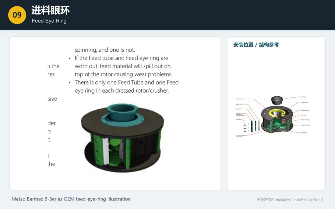
Feed Eye Ring
- Equipment Configuration
- Barmac / Enclosed Rotor
- Installation and Function
- Central feed opening at the top of the rotor
- Material Options
- High-Chromium White Cast Iron / Wear-Resistant Alloy Cast Steel
10
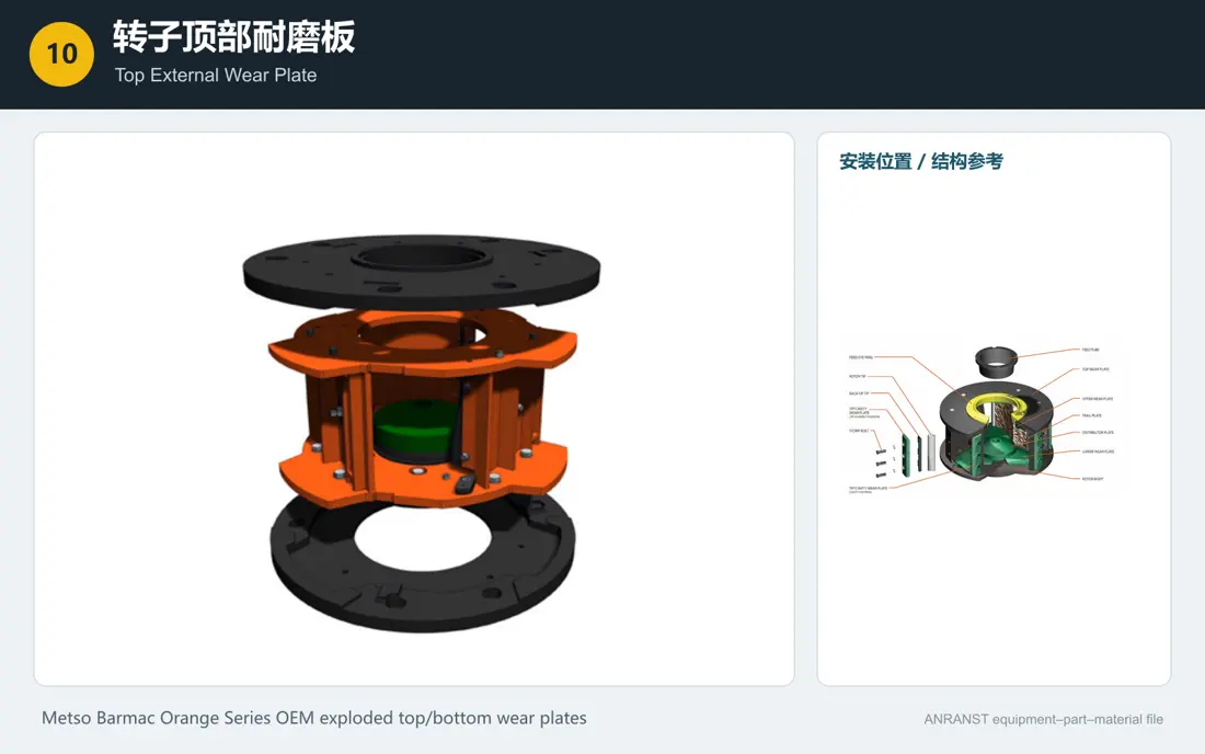
Top External Wear Plate
- Equipment Configuration
- Barmac / Enclosed Rotor
- Installation and Function
- External top surface of the rotor body
- Material Options
- Wear-Resistant Steel; Hardened Wear Lip. Confirm hardness, tensile strength and other numerical properties against a material specification, manufacturer data or approved project record before publishing.
11
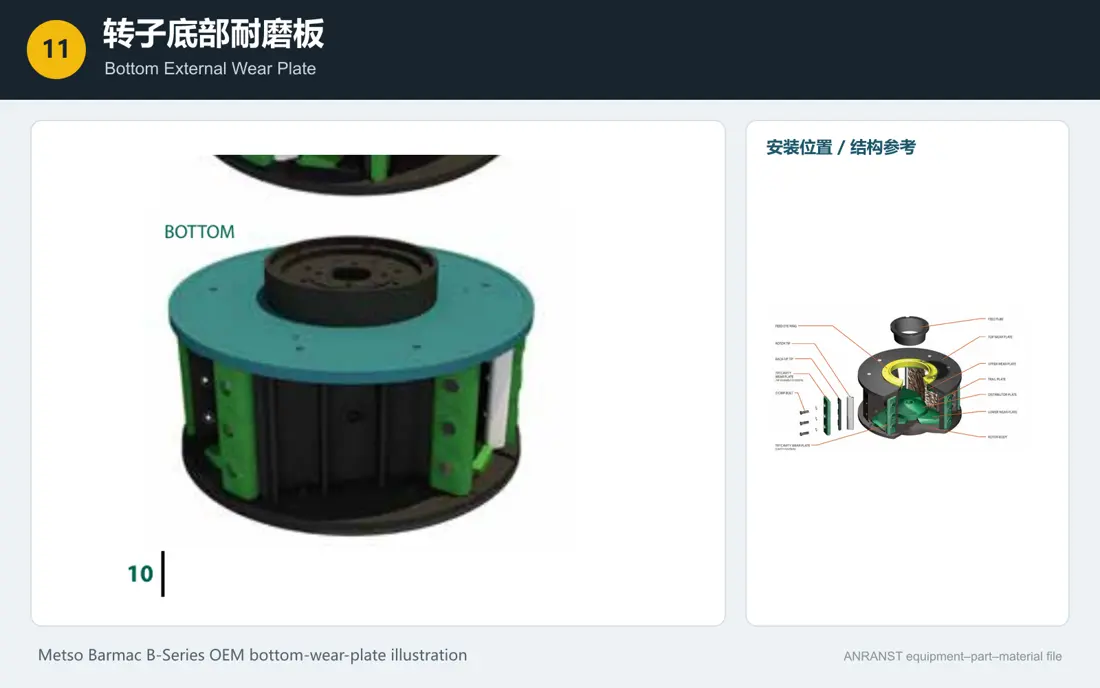
Bottom External Wear Plate
- Equipment Configuration
- Barmac / Enclosed Rotor
- Installation and Function
- External bottom surface of the rotor body
- Material Options
- Wear-Resistant Steel; Hardened Wear Lip. Confirm hardness, tensile strength and other numerical properties against a material specification, manufacturer data or approved project record before publishing.
12
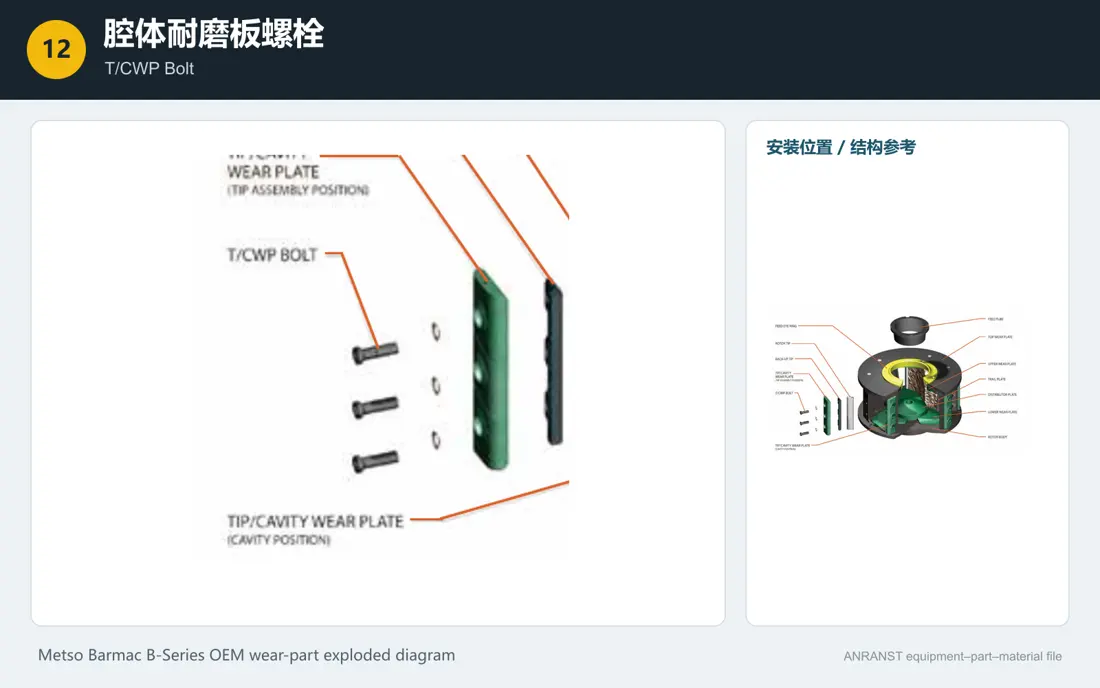
T/CWP Bolt
- Equipment Configuration
- Conventional Barmac Rotor
- Installation and Function
- Fixing point for the port cavity wear plate
- Material Options
- Property class 10.9/12.9 alloy steel fasteners or OEM-specific fasteners
13
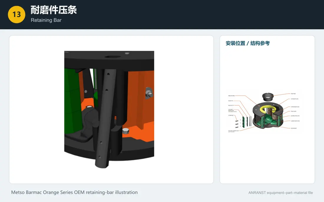
Retaining Bar
- Equipment Configuration
- Orange Series RC Rotor
- Installation and Function
- Vertical locking position at each rotor port
- Material Options
- 42CrMo/4140 Quenched and Tempered Steel or OEM High-Strength Wear-Resistant Steel
14
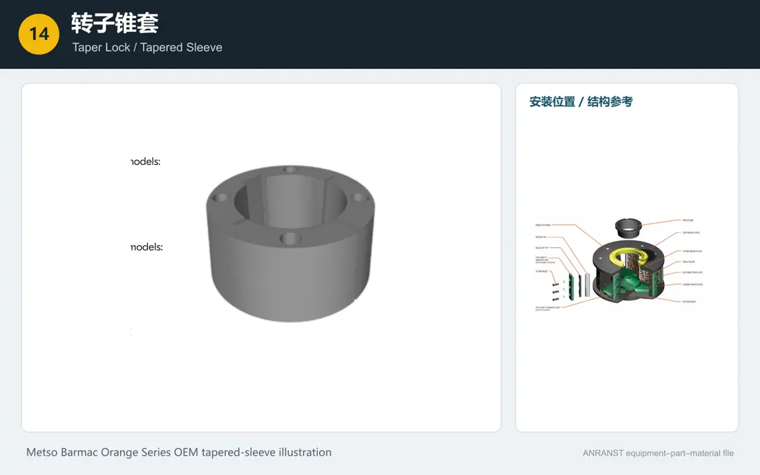
Taper Lock / Tapered Sleeve
- Equipment Configuration
- Taper-bush shaft arrangements, including MK/8000
- Installation and Function
- Between the tapered main shaft section and the rotor hub
- Material Options
- 42CrMo/4140 Quenched and Tempered Alloy Steel
15
Rotor Boss
- Equipment Configuration
- Enclosed Rotor
- Installation and Function
- At the rotor center, below the distributor plate
- Material Options
- High-Strength Cast Steel / Forged Alloy Steel / High-Strength Welded Structure
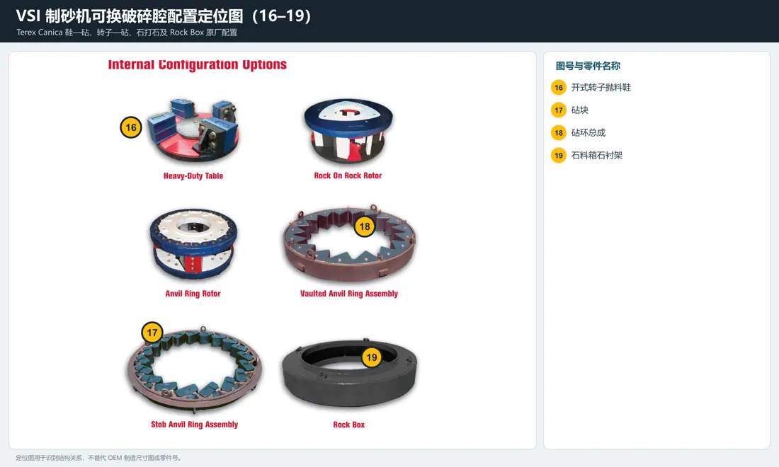
16
Open-table Shoe / Impeller
- Equipment Configuration
- Shoe-and-Anvil / Mag’Impact Chamber
- Installation and Function
- Outer edge of the open rotor table
- Material Options
- High-Chromium White Cast Iron / Martensitic Steel / WC or Ceramic MMC
17
Anvil
- Equipment Configuration
- Rock-on-Steel Chamber
- Installation and Function
- Stationary working surface around the rotor
- Material Options
- High-Chromium White Cast Iron / Martensitic Steel / MMC
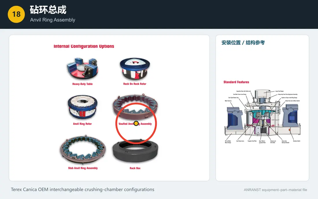
18
Anvil Ring Assembly
- Equipment Configuration
- Rock-on-Steel Chamber
- Installation and Function
- Around the rotor, inside the housing
- Material Options
- High-Strength Steel Ring Frame with Replaceable Anvils and High-Strength Fasteners
19
Rock Box / Rock Shelf
- Equipment Configuration
- Rock-on-Rock Chamber
- Installation and Function
- Rock bed area around the rotor
- Material Options
- High-Strength Steel Frame with Localized Wear Parts and an Autogenous Rock Bed
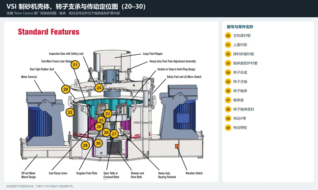
20
Mainframe Liner
- Equipment Configuration
- Common to Multiple Designs
- Installation and Function
- Inner wall of the crushing chamber
- Material Options
- High-Chromium Castings ; Wear-Resistant Steel. Confirm hardness, tensile strength and other numerical properties against a material specification, manufacturer data or approved project record before publishing.
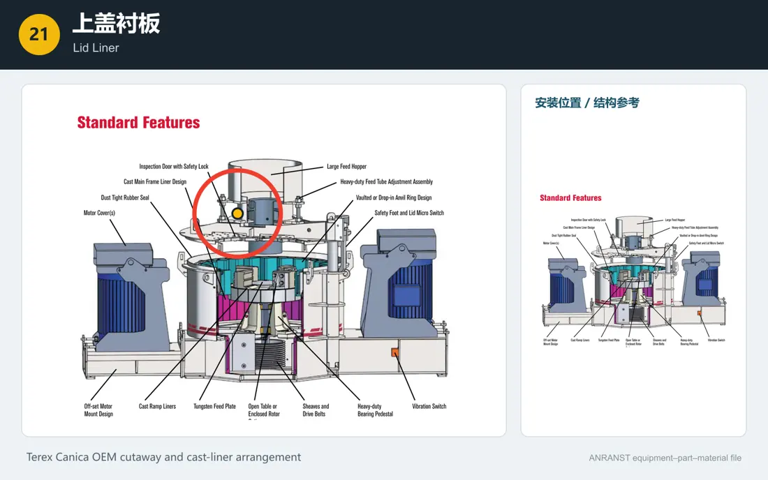
21
Lid Liner
- Equipment Configuration
- Models with an Opening Top Cover
- Installation and Function
- Inner surface of the top cover
- Material Options
- High-Chromium ; Wear-Resistant Steel. Confirm hardness, tensile strength and other numerical properties against a material specification, manufacturer data or approved project record before publishing.
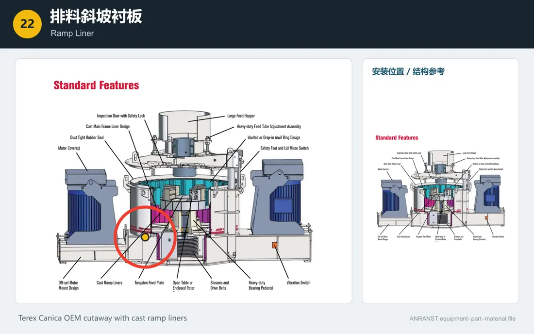
22
Ramp Liner
- Equipment Configuration
- Common to Multiple Designs
- Installation and Function
- Slope below the rotor leading to the discharge opening
- Material Options
- High-Chromium Castings / Wear-Resistant Steel / Hardfaced or Ceramic Composite
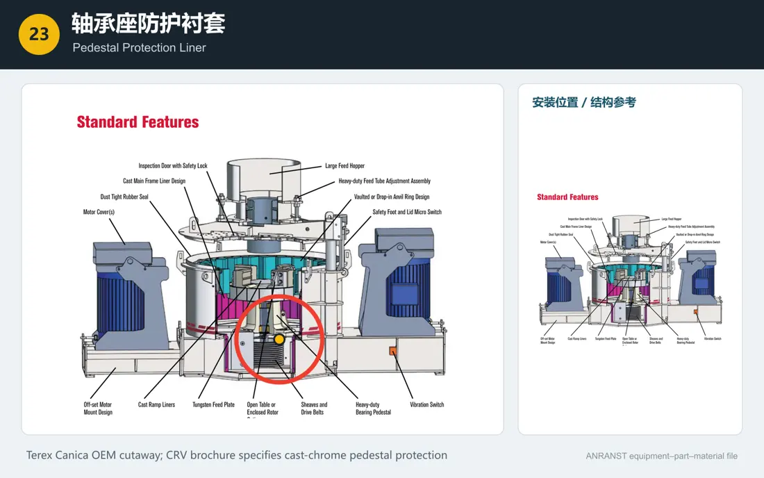
23
Pedestal Protection Liner
- Equipment Configuration
- Designs with external protection, including Canica
- Installation and Function
- Around the main shaft, above the bearing housing
- Material Options
- Cast Chrome / High-Chromium Wear-Resistant Castings
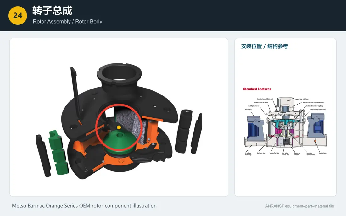
24
Rotor Assembly / Rotor Body
- Equipment Configuration
- Common to Multiple Designs
- Installation and Function
- Center of the crushing chamber
- Material Options
- High-Strength Welded Structural Steel / Cast Steel with a Complete Set of Wear Parts
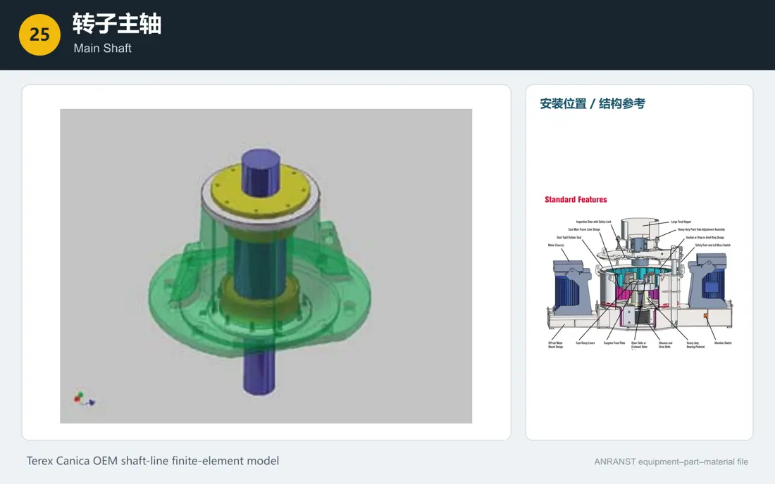
25
Main Shaft
- Equipment Configuration
- Common to Multiple Designs
- Installation and Function
- Passes vertically through the bearing housing
- Material Options
- Canica Astralloy / 42CrMo / 4140 / 34CrNiMo6 Forged Steel
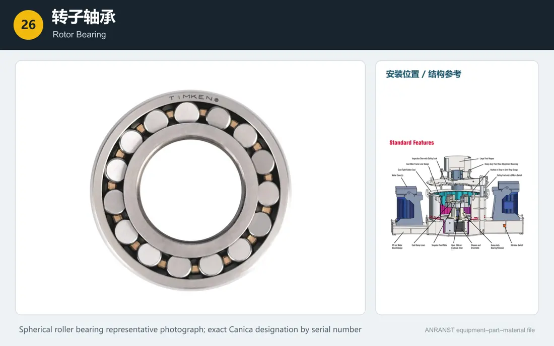
26
Rotor Bearing
- Equipment Configuration
- Common to Multiple Designs
- Installation and Function
- Inside the vertical main shaft bearing housing
- Material Options
- 100Cr6/SAE 52100 Bearing Steel
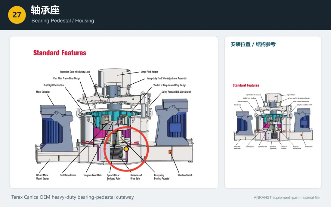
27
Bearing Pedestal / Housing
- Equipment Configuration
- Common to Multiple Designs
- Installation and Function
- Central support position below the rotor
- Material Options
- Ductile Iron / Cast Steel / High-Strength Welded Structural Steel
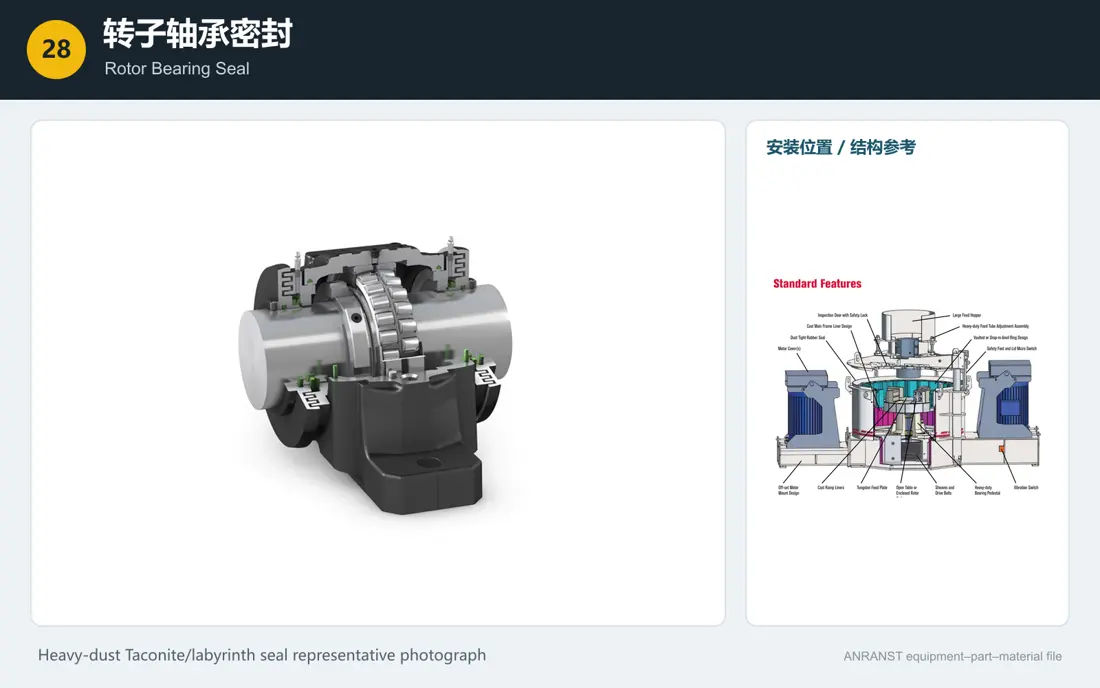
28
Rotor Bearing Seal
- Equipment Configuration
- Common to Multiple Designs
- Installation and Function
- Contamination barrier where the main shaft exits the bearing housing
- Material Options
- Labyrinth/Taconite + NBR/HNBR/FKM/V-ring
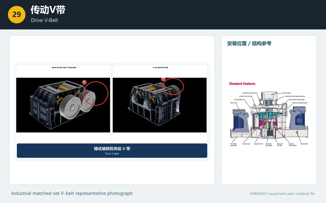
29
Drive V-Belt
- Equipment Configuration
- Belt-Driven Models
- Installation and Function
- Between the motor and main shaft pulleys
- Material Options
- EPDM / Chloroprene Rubber with Polyester / Aramid Tensile Cords
30
Drive Sheave / Pulley
- Equipment Configuration
- Belt-Driven Models
- Installation and Function
- Lower end of the main shaft and the motor shaft end
- Material Options
- Gray Iron / Ductile Iron / Cast Steel or Fabricated Steel Pulley
Materials for similarly named parts may differ by OEM, machine model and operating conditions. Confirm the machine model, drawing and measured dimensions before ordering or manufacture.
7. Procurement and Acceptance Checks
1. Confirm the manufacturer, model, serial number, rotor diameter and depth, port count, and ROR, ROS, shoe-and-anvil or Mag’Impact chamber configuration. 2. Conventional Barmac and Orange Series RC rotors use different retainers, bolts, cavity plates and upper and lower plate fastenings; do not order simply by the label “Barmac parts.” 3. Assemble rotor tips, backup tips, cavity plates, internal upper and lower plates and distributor plates in OEM-specified mass-matched sets, distributed evenly across the ports. 4. Recheck runout and dynamic balance after rotor weld repairs, material changes, hub or taper-bush replacement, or complete wear-set replacement. 5. For WC-Co, high-chromium or MMC upgrades, check maximum feed size, speed, tramp material and impact loading to avoid chipping failures. 6. Inspect mainshafts, hubs and taper bushes for material, heat treatment, UT/MT, taper contact, circular runout and connection torque. 7. Record the complete bearing designation, clearance, fits, mounting temperature, lubricant, seals, baseline vibration and temperature rise. 8. Check liner material, segment profile, seating, hole positions, height alignment, fastening and safe rotor clearance.
Materials for similarly named parts may differ by OEM, machine model and operating conditions. Confirm the machine model, drawing and measured dimensions before ordering or manufacture.