Metso Barmac B Series Vertical Shaft Impact Crushers

Use B6150SE, B7150SE, B9100SE and historical B5100SE models to identify rotor wear parts, tungsten-carbide materials, shafts, drives and dedicated maintenance tools.

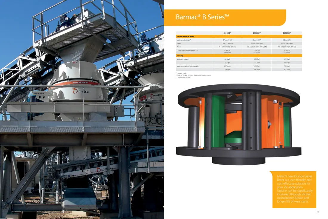
OEM reference for the Metso Barmac B6150SE installation and B Series models
Official Metso B Series installation image, B6150SE / B7150SE / B9100SE model table and Orange Series rotor.
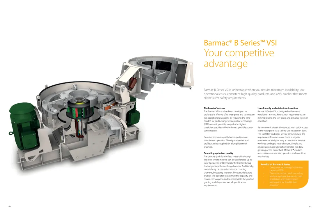
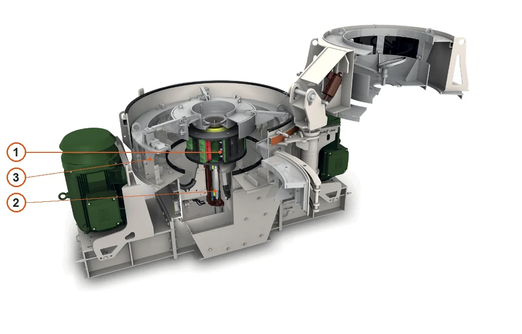
OEM cutaway drawing of Metso Barmac B Series VSI
Official Barmac B cutaway showing upper feed, rotor, vertical shaft, belt drive and maintenance areas.
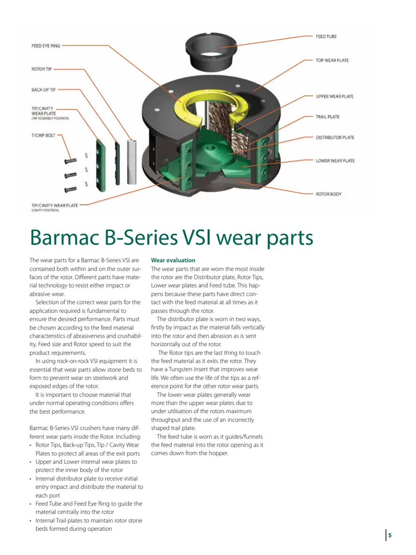
OEM diagram of rotor wear-part positions in Metso Barmac B Series
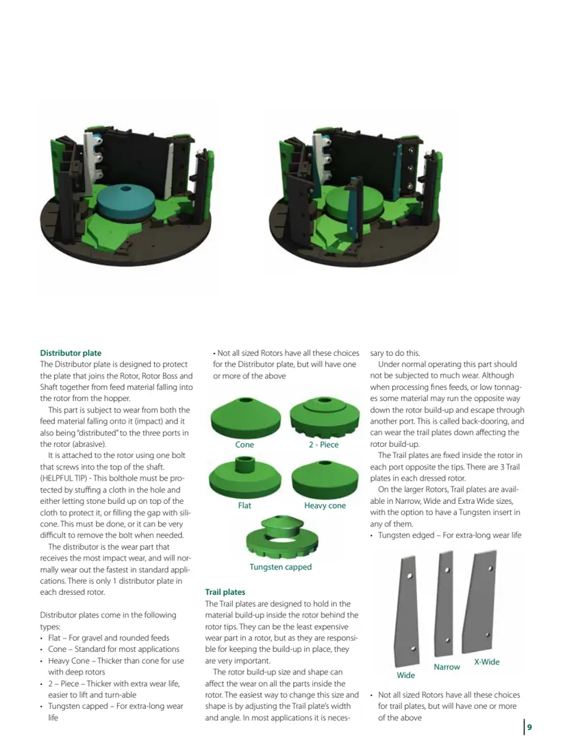
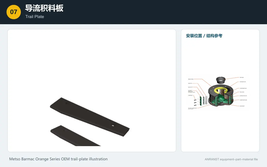
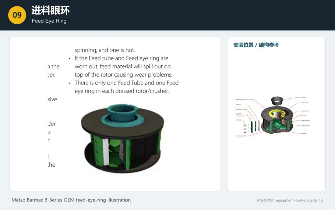
Official Metso rotor wear-part layout: tips, backup tips, cavity plates, upper/lower plates, distributor plate, trail plates, feed tube and feed eye ring.
OEM Equipment Series

Models, Rotor Wear Parts, Shafts and Tooling on One Page

This page uses original Metso Barmac model, rotor and wear-part literature. Published data identify installations; part supply still requires the full model, rotor dimensions, serial number, drawing and drawings.

3 + 1Current and Historical Installed Models
10Rotor Wear-Part Categories
6Shaft and Drive Spares
3OEM WC Performance Grades
Models and key specifications

Barmac B Series Model Table

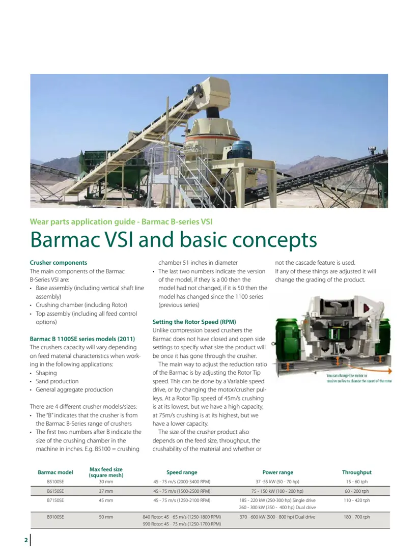
The three current models use current OEM B Series literature. B5100SE comes from the 2011 OEM wear-parts application guide and is retained explicitly as a historical installed model.

Model / StatusMaximum FeedSpeedPowerCapacity / Weight
B6150SE · Current37 mm1,500–2,500 rpm75–160 kW60–217 t/h; approximately 6,400 kg (including motor)
B7150SE · Current45 mm1,100–2,100 rpm160–320 kW125–545 t/h; approximately 12,400 kg (including motor)
B9100SE · Current50 mm1,000–1,800 rpm320–600 kW263–775 t/h; approximately 14,400 kg (including motor)
B5100SE · Historical Installation30 mm2,000–3,400 rpm37–55 kW15–60 t/h; confirm weight from installation records
Installation checks: Capacity depends on feed properties, crushability, abrasiveness, rotor speed and cascade ratio. Machines of the same model may still differ in rotor size, deep/shallow design and part versions. Original B Series Model Literature · Original Barmac Wear-Parts Guide
Metso

Component Location Diagram

The numbers on the diagram correspond one to one with the rows below.

Metso Barmac B Series VSI – Component Location Diagram
No.ComponentLocationApplies to
1RotorGreen and black rotor assembly at centre of chamberBarmac B Series
2Main shaftCentral vertical shaft beneath rotorBarmac B Series
3Crushing chamber bodyGrey chamber body surrounding rotorBarmac B Series
Wear parts

Identify Barmac Wear Parts by Internal and External Rotor Position

Tips face high-speed discharge impact; distributor plates face feed impact and abrasion. Upper/lower and trail plates maintain the rotor rock bed. Material selection must account for position and failure mode.

Metso Barmac Rotor Tip Group Identification Figures
01

Rotor Tip Sets

Rotor Tip Set

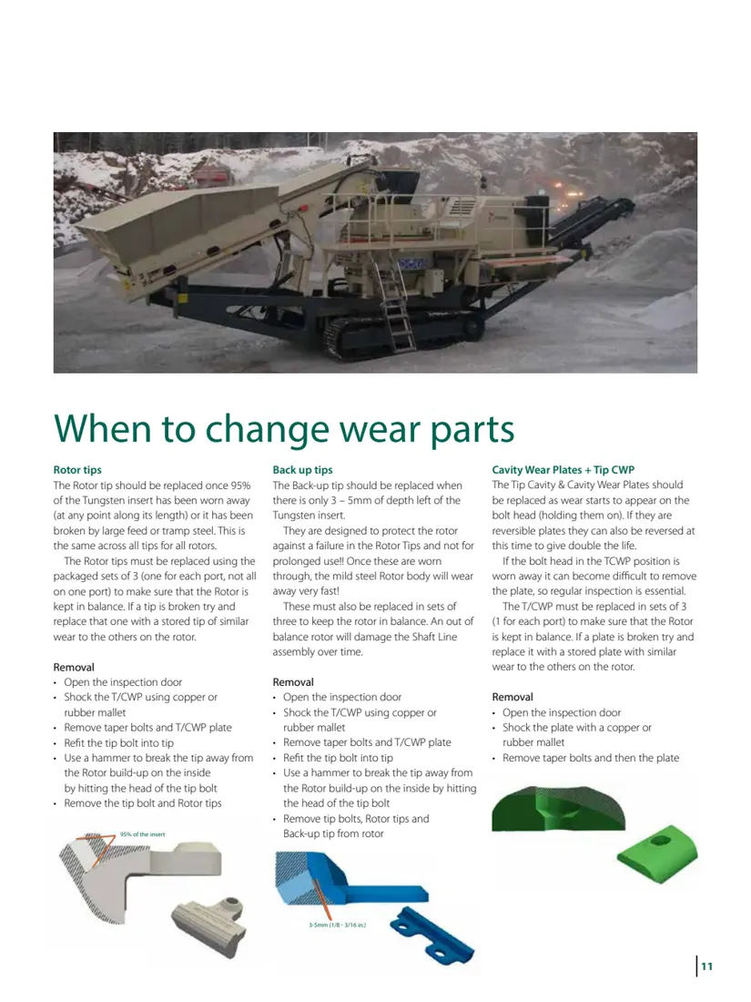
The last high-wear parts contacted before material leaves the rotor. OEM literature lists Hard, Extra Hard and XX Hard tungsten-carbide inserts with different impact/abrasion balances. Replace matched sets at each outlet to maintain balance. Verify parts by full Barmac model, rotor size, serial number, drawing, profile and interfaces.

View the General Component Page →
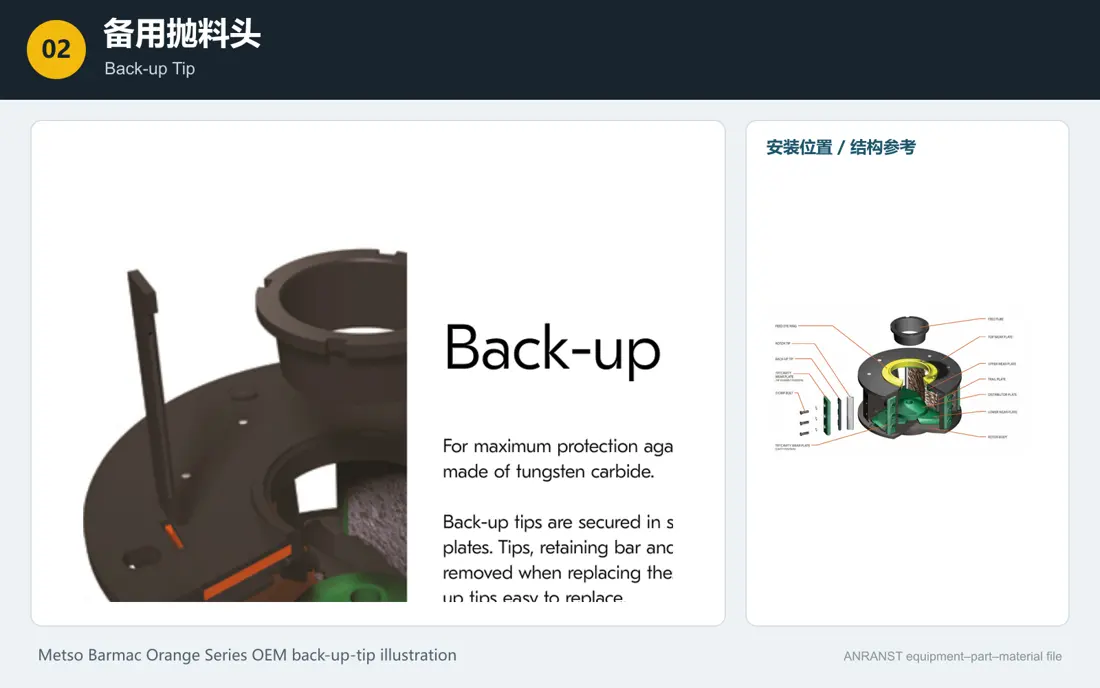
Metso Barmac Backup Rotor Tip Identification Figures
02

Backup Rotor Tips

Back-up Tip

Behind the main tips, these protect the rotor if a tip breaks or wears through. They provide short-term protection and are not intended for continued long-term running. Verify full Barmac model, rotor size, serial number, drawing, profile and interfaces.

View the General Component Page →
Metso Barmac Terminal / Clapular wearables plate Identification Figures
03

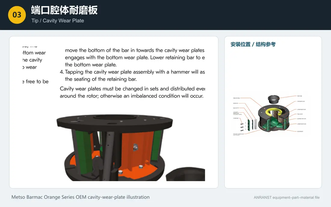
Tip / Cavity Wear Plates

Tip / Cavity Wear Plate

Protect outlet edges and exposed faces from high-speed rebound impact. OEM instructions require matched, evenly distributed sets; reversible designs are turned according to wear. Verify full Barmac model, rotor size, serial number, drawing, profile and interfaces.

View the General Component Page →
Metso Barmac Retardant pads on the inside Identification Figures
04

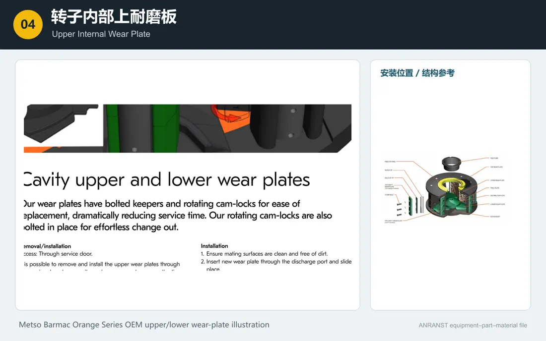
Upper Internal Wear Plates

Upper Internal Wear Plate

Protect upper internal surfaces and stabilise the rotor rock bed. The OEM guide does not offer freely interchangeable materials, so confirm material and profile against original drawings, full model, rotor size, serial number and interfaces.

View the General Component Page →
Metso Barmac Internal underwear wearables Identification Figures
05

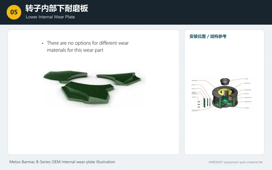
Lower Internal Wear Plates

Lower Internal Wear Plate

Protect lower internal surfaces and usually wear faster than upper plates. A complete rotor has three upper and three lower plates, replaced as sets to maintain balance. Verify full Barmac model, rotor size, serial number, drawing, profile and interfaces.

View the General Component Page →
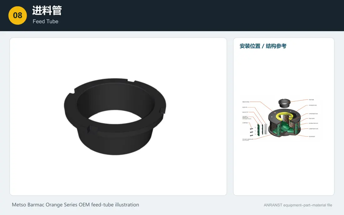
Metso Barmac Feed Pipe Identification Figures
08

Feed Tube

Feed Tube

Fixed in the upper feed assembly, it directs all feed into the rotor opening and faces continuous abrasion. Some rotors have different openings for high/low capacities. Verify full Barmac model, rotor size, serial number, drawing, profile and interfaces.

View the General Component Page →
Spare parts

Rotors, Vertical Shafts, Bearings, Seals and Belt Drives

Only spare systems identifiable in the original Barmac design are listed. Verify interfaces, accuracy, configuration and interchangeability against the full machine model, serial number and drawings.

Metso Barmac Rotor Assemblies Transit-prime Identification Figures
01

Rotor Assembly and Body

Rotor Assembly / Rotor Body

The B Series main rotating assembly includes the body, rock-bed areas and wear-part mounts. Complete supply requires rotor diameter, deep/shallow design, outlet count and balance checks, plus full Barmac model, serial number, drawing, profile and interfaces.

View the General Component Page →
Metso Barmac axis and axle aggregate Identification Figures
02

Vertical Shaft and Shaft Assembly

Vertical Shaft Line Assembly

Located in the base assembly, supporting the rotor and transmitting high-speed loads. Verify journals, tapers, threads, heat treatment, non-destructive testing and balance against original drawings and serial number, plus full model, rotor size, profile and interfaces.

View the General Component Page →
Metso Barmac Rotor Bearing Identification Figures
03

Rotor Bearings

Rotor Bearing

Carry the high-speed vertical shaft. Bearing designation, clearance, fits, lubricant quantity, temperature rise and matched arrangement require shaft records, not inference from similar models. Verify full Barmac model, rotor size, serial number, drawing, profile and interfaces.

View the General Component Page →
Metso Barmac Groups Drive V-Belt Identification Figures
06

Matched Drive V-Belt Sets

Matched Drive V-Belt Set

Matched consumables for the high-speed drive. Replace and adjust the whole set for section, effective length, count, capacity and tension. Verify full Barmac model, rotor size, serial number, drawing, profile and interfaces.

View the General Component Page →
Dedicated Tooling

Barmac OEM Lifting and Rotor Maintenance Tools

Current Metso product pages and B Series literature explicitly list top lifting, rotor service arms and maintenance lifting tools. Confirm applicability by machine model and site configuration.

BARMAC B SERIESOEM reference for the Metso Barmac lid and upper-section lifting device

Lid / Upper-Section Lifting Device

Moves the lid and upper feed assembly to expose the rotor. Check model, lifting load, swing space, mounting foundation and safety locks.

BARMAC B SERIESOEM reference for the Metso Barmac rotor service arm

Rotor Service Arm and Lifting Tools

Support rotor removal, transfer and positioning, reducing reliance on external cranes for routine maintenance. Verify lifting points, rotor weight, arm length and working radius by model.

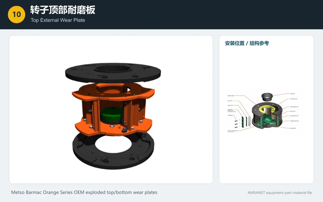
BARMAC B SERIESOEM reference for Metso Barmac rotor wear-part maintenance

Rotor Wear-Part Replacement and Balancing

Replace tips, backup tips and cavity plates in evenly matched sets at each outlet. Tools and replacement sequence must maintain rotor balance and personnel safety.

FAQ

Frequently asked questions

What information is needed to quote Barmac rotor wear parts?

Provide the full model, serial number, rotor diameter and deep/shallow design, part drawing, current-part photographs, feed size, abrasiveness, rotor speed and used-part wear condition.

Are wear parts interchangeable between B Series models?

The B Series name alone is insufficient. Verify rotor size, deep/shallow design, outlets, part profile, drawing, serial number and dynamic-balance configuration.

How is the WC grade for rotor tips selected?

OEM literature distinguishes impact-oriented, abrasion-oriented and high-wear-resistance/low-impact-resistance carbide grades. Feed size, hardness, abrasiveness, moisture and tramp-metal risk determine the final choice.

Send the Barmac Model, Rotor Size or Part Drawing

Provide the full model, serial number, rotor configuration, part drawing, used-part photographs, key dimensions, current material and duty. These support identification, material assessment, manufacturing coordination, quality control and finished-part delivery.

Equipment Brand and ModelDrawingDrawing or DimensionsCurrent MaterialPhotographs of Failed PartsTarget Service LifeOperating Conditions
Request a Quote

Or contact us directly: +86 156 3797 3199
zzx@anranst.com

Manufacturing Services in China

From Technical Assessment to Finished-Part Delivery

ANRANST provides customers worldwide with engineering assessment, production at certified foundries to the customer technical requirements, quality control and finished-part delivery for custom wear parts and industrial spares, with scope to support other custom industrial parts.

01

Drawing and Engineering Review

We review mating surfaces and interface dimensions and assess material, heat treatment and manufacturing feasibility.

02

Material and Heat-Treatment Specification

Material grades and heat-treatment processes are specified order by order, stated in the technical agreement and tracked through production.

03

Quality Control

Drawing confirmation, material and process control, production tracking, inspection and acceptance coordination.

04

Finished-Part Delivery

We coordinate manufacturing, quality confirmation, packaging and delivery of complete finished parts in a workable, closed-loop supply process.

Provide the existing model, drawings, drawing, materials or operating conditions so we can identify the appropriate technical review and supply route.

Submit an Enquiry