CITIC HIC GM High-Pressure Grinding Roll

Start with GM140-60, GM240-170 and roll diameter × width, then identify the roll surface, studs, edge protection, cheek plates, bearings, hydraulics, materials and inquiry requirements.

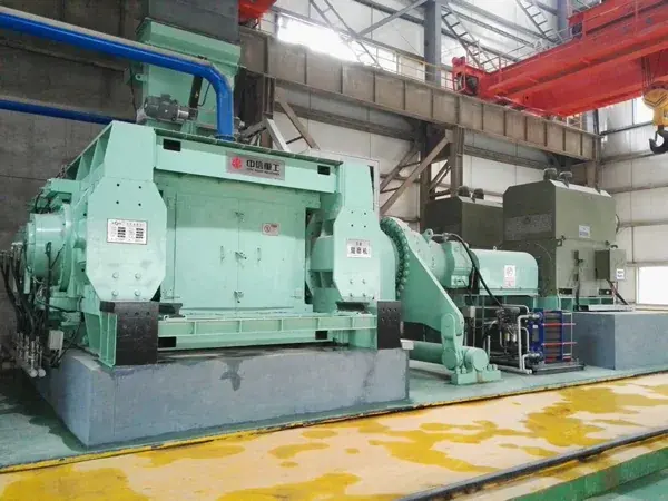
Official CITIC HIC HPGR product image
Official CITIC HIC HPGR product image. Confirm the installed machine from the complete GM model, roll diameter, roll width, project nameplate and equipment documentation.
OEM Equipment Details

Models, Roll-Surface Wear Systems and Core Spares on One Page

This page uses GM140-60 and GM240-170 to organize model identification and spare-part paths. Confirm other installed models from the complete nameplate and project documentation.

2 Main Published Models
1,400–2,400 mm Nominal Roll Diameter
600–1,700 mm Nominal Roll Width
10 Core Part Paths
Standard Models and Key Dimensions

GM Models and Core Nominal Dimensions

The numbers in a GM model identify nominal roll diameter and width. Confirm the actual power, pressure, capacity, roll-surface configuration and bearing system from project documentation.

ModelNominal Roll DiameterNominal Roll WidthRequired Checks Before Manufacturing
GM140-601,400 mm600 mmProject nameplate, roll-surface type, bearings, hydraulics and drawing revision
GM240-1702,400 mm1,700 mmProject nameplate, roll-surface type, bearings, hydraulics and drawing revision

Nominal model dimensions do not replace manufacturing dimensions for the roll surface, studs or structural parts. Confirm roll-surface type, hole pattern, edge protection and fits from the original drawings.

Wear Parts

Roll Surface, Stud, Edge Protection and Chute Wear Systems

Roll surfaces and studs are presented first. Different positions are exposed to high contact stress, abrasive wear, edge wear or feed impact, so materials and manufacturing processes are confirmed separately.

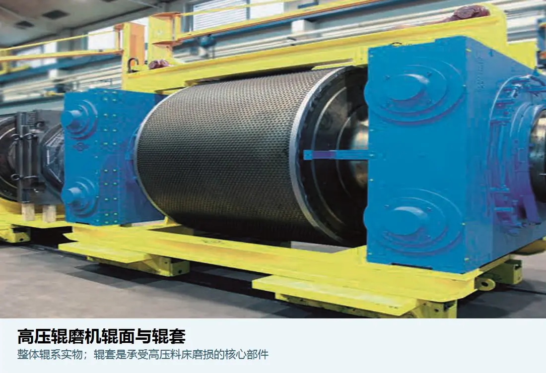
Roll surface / roll tire identification image
01

Roll Surface / Roll Tire

Roll Surface / Roller Tyre

Directly grips and compresses the material bed and is the HPGR's principal wear zone. Confirm roll diameter, roll width, surface construction, base material, assembly method and wear zones.

Material Selection: Forged alloy-steel base with studs, hardfacing or composite wear construction. Confirm material and process according to ore, pressure, particle size and maintenance method.

View Part Details →
Roll-surface stud identification image
02

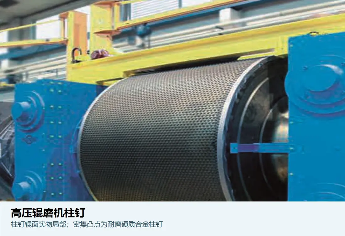
Roll Studs

Roller Stud

Embedded in the roll surface to form an autogenous wear-protection layer while resisting high contact stress and abrasive wear. Confirm diameter, length, head shape, layout, hole diameter and fit.

Material Selection: Confirm the cemented-carbide system and its fit with the base according to impact, ore abrasiveness, stud-breakage records and press-fitting process.

View Part Details →
Edge protection block / edge liner identification image
03

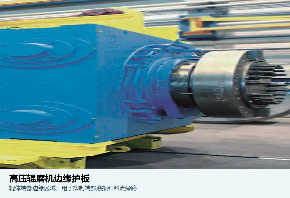
Edge Protection Block / Edge Liner

Edge Protection / Edge Liner

Protects roll-surface edges and controls edge wear. Confirm left/right orientation, segmentation, profile, fastening arrangement, roll-surface interface and wear height.

Material Selection: Confirm cemented carbide, wear-resistant alloy steel or composite construction according to edge pressure, impact and replacement method.

View Part Details →
Cheek plate / side liner identification image
04

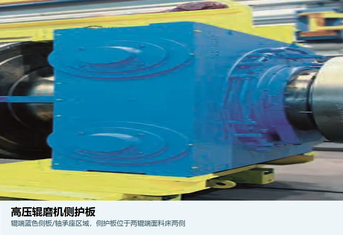
Cheek Plate / Side Liner

Cheek Plate / Side Liner

Located on both sides of the roll gap to limit lateral material escape while resisting severe wear. Confirm clearance, profile, left/right orientation, support construction and adjustment range.

Material Selection: Confirm quenched-and-tempered wear plate, composite wear plate or ceramic-composite construction according to abrasive wear, impact and clearance stability.

View Part Details →
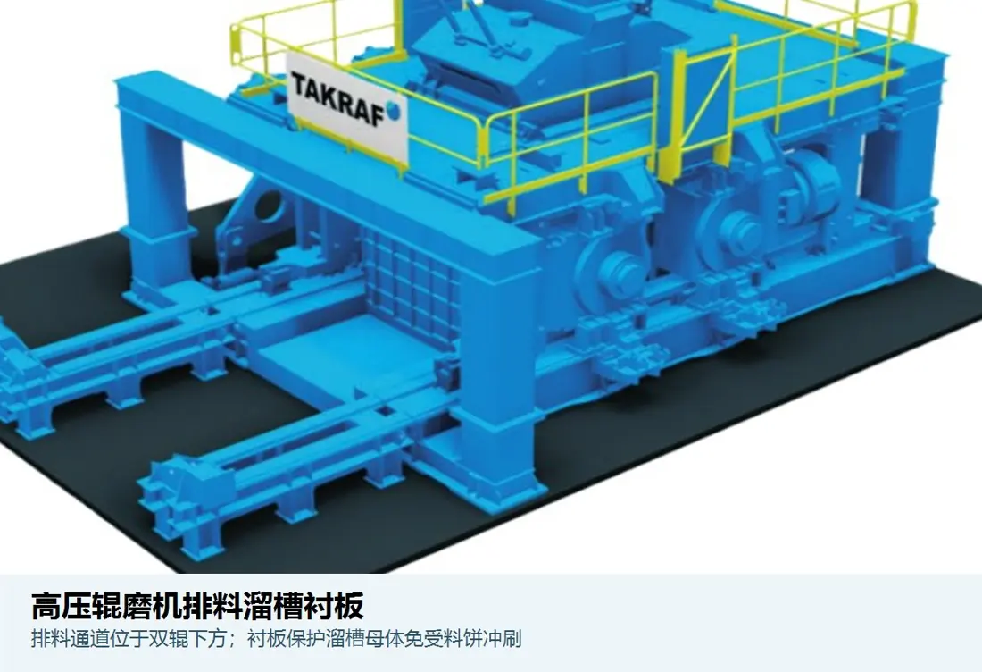
Discharge-chute liner identification image
06

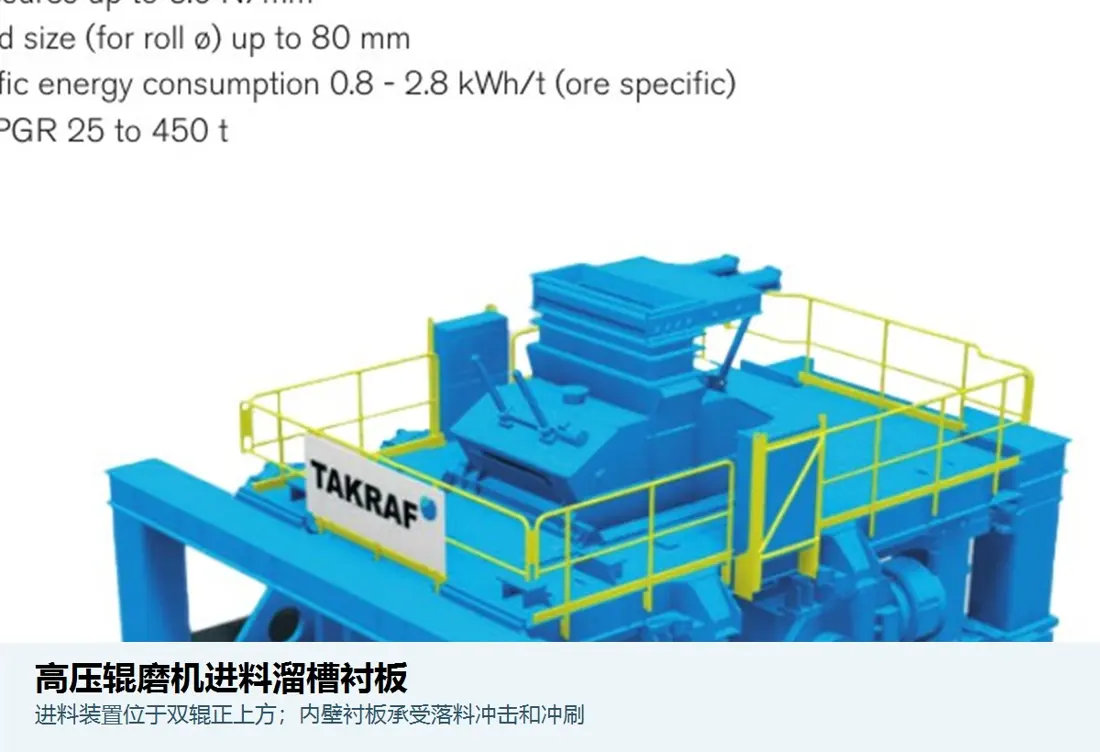
Discharge Chute Liners

Discharge Chute Liner

Protects the product-cake discharge and transfer area. Confirm flow direction, segmentation, thickness, curved surfaces, hole pattern, supports and adjacent-equipment interfaces.

Material Selection: Confirm quenched-and-tempered wear plate, high-chromium cast iron, ceramic or composite wear construction according to particle size, velocity and impact.

View Part Details →
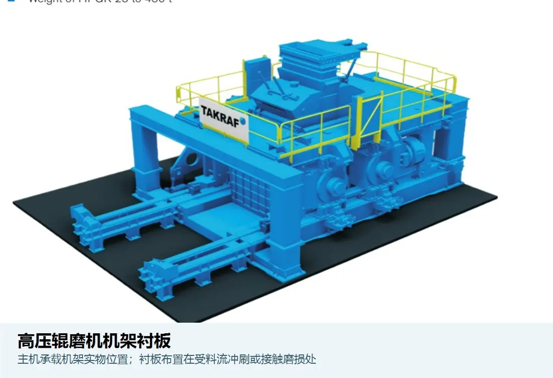
Press-frame liner identification image
07

Press-Frame Liner

Press Frame Liner

Protects the press frame and adjacent feed-receiving area. Confirm installation zone, thickness, hole pattern, welded or bolted attachment and maintenance access.

Material Selection: Confirm quenched-and-tempered wear plate or composite wear plate according to impact, abrasive wear, weldability and replacement method.

View Part Details →
Spare Parts

Bearing, Seal, Hydraulic and Scraper Spares

Check support and hydraulic parts separately against the complete model, load, interfaces, fits, tolerances, lubrication, pressure, material and seal combination.

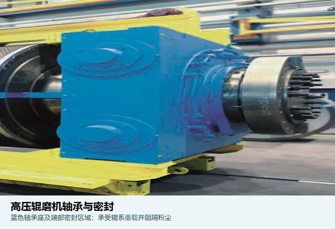
Roll-bearing and bearing-seal identification image
01

Roll Bearings and Bearing Seals

Bearing & Bearing Seal

Supports the roll assembly and isolates dust and lubricant. Confirm the complete bearing designation, clearance, journal, housing bore, tolerances, seal combination and lubrication system.

Material Selection: Use bearings and seals to the original specification. Confirm bearing housings and shaft parts according to load, temperature rise, fits and inspection requirements.

View Part Details →
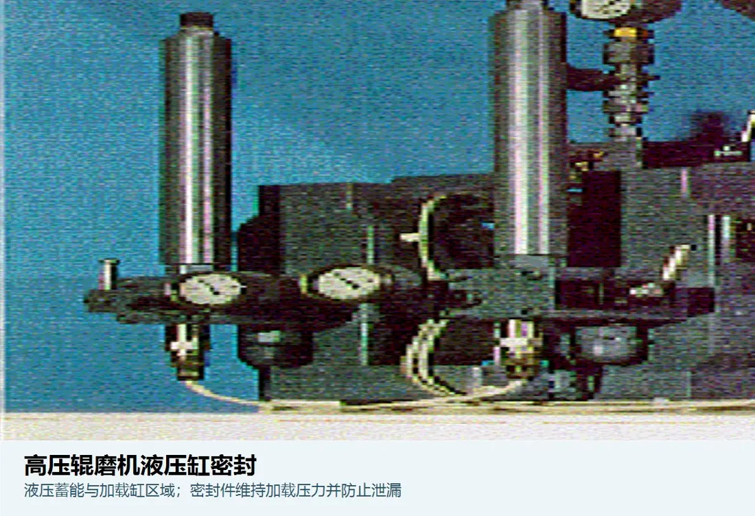
Hydraulic-cylinder seal identification image
02

Hydraulic Cylinder Seal

Hydraulic Cylinder Seal

Maintains pressure in the roll-loading system and excludes contaminants. Confirm cylinder bore, rod diameter, groove, operating pressure, temperature, fluid and seal-stack orientation.

Material Selection: Confirm polyurethane, NBR, HNBR, FKM, PTFE or composite seals according to pressure, temperature, speed and hydraulic fluid.

View Part Details →
Scraper / cleaner identification image
03

Scraper / Cleaner

Scraper / Cleaner

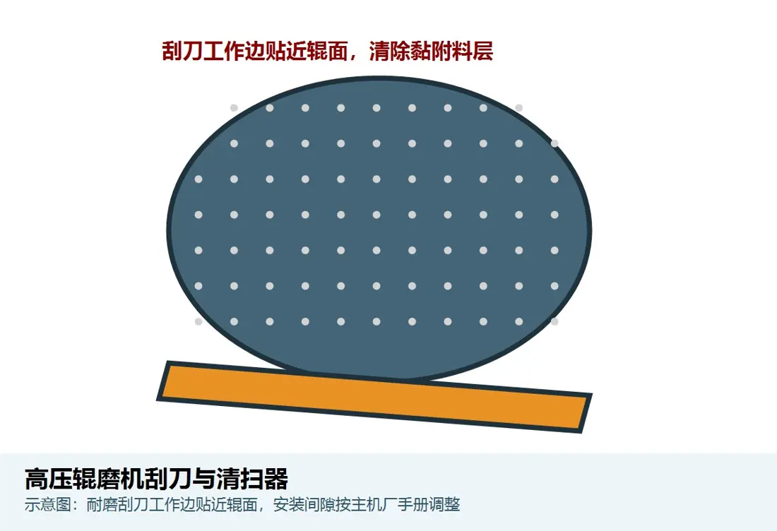
Removes adhering material from the roll surface or adjacent area. Confirm position, direction, blade profile, clearance, bracket, preload and roll-surface construction.

Material Selection: Confirm quenched-and-tempered wear steel, polyurethane or composite scraper blades according to material adhesion, wear, temperature and roll-surface protection requirements.

View Part Details →
Drawing and Spare Part Numbers

GM Drawing Number and Third-Party Part Number Check

GM part numbers must be confirmed against the complete model, installation position and drawing revision. Numbers are not inferred on this page.

Selection Guidelines: Part numbers must match the model, installation position and installed-equipment drawings. OEM drawing numbers and third-party part numbers are checked separately.

Can the numbers in GM140-60 and GM240-170 be used directly as part dimensions?

No. They identify the machine's nominal roll diameter and width; they are not manufacturing dimensions for the roll tire, studs, edge blocks or cheek plates.

Are HPGR studs interchangeable when the cemented-carbide grade is the same?

No. Also confirm geometry, hole pattern, fit, base material, press-fitting process, ore, pressure, stud-breakage mode and roll-surface maintenance strategy.

How can GM parts be identified without a drawing number?

Submit the nameplate, roll diameter and width, equipment general arrangement, installation position, used-part photographs, roll-surface wear records and key dimensions to assess identification, reverse engineering and manufacturing requirements.

Submit the CITIC HIC GM model, drawing number, roll-surface construction or spare-part requirement

Provide the complete model, roll diameter, roll width, serial number, drawings, used-part photographs, materials and operating conditions. We will use them for part identification, material assessment, manufacturing matching, quality control and finished-part delivery.

Manufacturing Services in China

From Technical Assessment to Finished-Part Delivery

ANRANST provides customers worldwide with coordinated consulting, supplier sourcing, quality control and finished-part delivery for custom parts, wear parts and industrial spares from China, with scope to support other custom industrial parts.

01

Technical Advice

Equipment and part identification, drawing review, material selection and manufacturing feasibility assessment.

02

Supplier Introductions

Match requirements with suitable manufacturers in China and coordinate the exchange of technical information.

03

Quality Control

Drawing confirmation, material and process control, production tracking, inspection and acceptance coordination.

04

Finished-Part Delivery

Coordinate manufacturing, quality confirmation, packaging and delivery of complete finished parts.

Provide the existing model, drawings, drawing or part numbers, materials or operating conditions so we can identify the appropriate technical review and supply route.

Submit an Enquiry