CITIC HIC PXZ Gyratory Crushers

From PXZ Standard Models and nominal size in Spider and Liners Abrasion system, Main Shaft and Protection bushings Extremely, Power Transmission Hydraulics, drawing number Confirmation and RFQ.

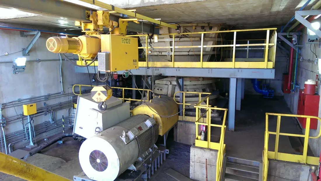
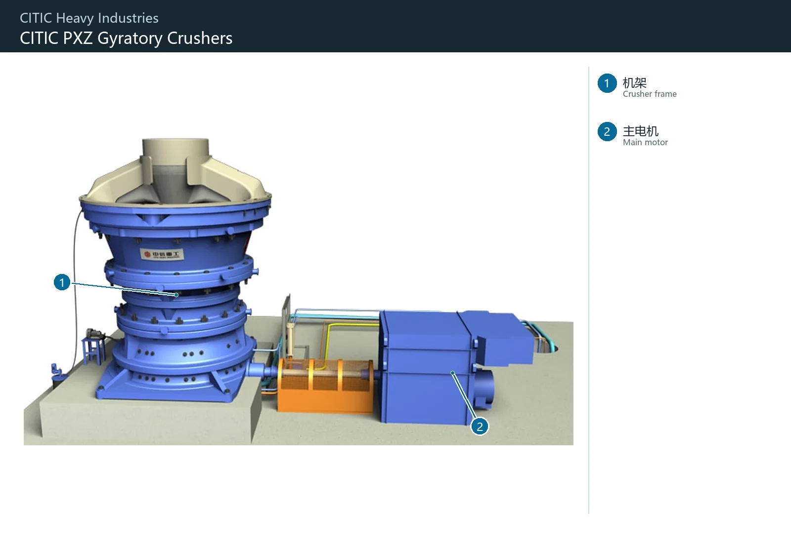
CITIC Heavy Industries PXZ Gyratory Crusher Official Product Picture
CITIC Heavy Industries Official gyratory crusher Product diagrams; specific installers PXZ complete model, Item nameplate, serial number and Equipment Documents confirmed.
OEM Equipment Details

model, wear parts, spare parts and drawing number Completed on a page

This page retains only models, nominal sizes and core installation positions that are directly relevant to the supply of Spare parts. The main shaft is displayed separately from a key protector bushinges without being mixed into one part as well.

10 PXZ Standard Models
30–72 in naming Feed Inlet Series
55–130 in naming Cone Bottom diameter Series
18 wear parts and Cores spare parts Entrance
Standard Models and Key Dimensions

PXZ Series Standard Models With nominal size

The two sets of numbers in the model are used to identify a nominal feedlot and cone bottom diameter series; manufacturing, quoting still requires checking project nameplates (complete models), serial number(r) drawing.

Modelnaming Feed Inletnaming Cone Bottom diameterValues of reconciliation
PXZ30-5530 in55 inby complete model, Item nameplate and general arrangement drawing Confirmation
PXZ42-6542 in65 inby complete model, Item nameplate and general arrangement drawing Confirmation
PXZ50-6550 in65 inAlready overseas Item Fixing the record; still must be serial number Confirmation
PXZ54-7554 in75 inCITIC Heavy Industries Public Item Data Confidential model
PXZ62-7562 in75 inCITIC Heavy Industries Public Item Data Confidential model
PXZ60-8960 in89 inby complete model, Item nameplate and general arrangement drawing Confirmation
PXZ70-8970 in89 inby complete model, Item nameplate and general arrangement drawing Confirmation
PXZ60-11060 in110 inby complete model, Item nameplate and general arrangement drawing Confirmation
PXZ63-13063 in130 inby complete model, Item nameplate and general arrangement drawing Confirmation
PXZ72-13072 in130 inby complete model, Item nameplate and general arrangement drawing Confirmation

naming model Cannot replace parts Manufacturing The same basis. model Differently Item s and Drawing Revision Possible still exist Construction or materials Differences.

Wear Parts

Spider, concave, mantle and Housing Abrasion system

Displaying beam protection, liner boards and mainshaft shield for bushshinges as well in the user'd identified priorities; each card connect to a single part page with material pages.

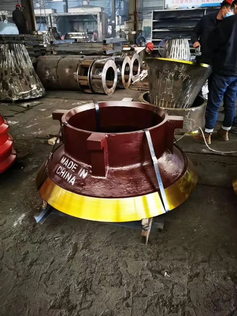
Spider stern, Spider Hats and Arm Guard Identification Figures
01

Spider stern, Spider Hats and Arm Guard

Spider Cap, Shield & Arm Liner

Locations Feed Inlet Above, withstand large ore shocks and overloading sliding wear. Converged Spider Arms Construction, plate type and direction of the hole system; thicknesses or feed orientation.

Material Selection: high-manganese steel, Quenched and Tempered Wear Plate or Composite wear-resistant construction Confidentialized by impact energy, plate thickness and fixed manner.

View Part Details →
gyratory crusher Mantles and Concaves System General Indications
02

Concave Liner

Concaves

Walks along Housing Sub-paragraph Mounting, and mantle Forming a crusher cavity. The number of layers, segments and outlines are corded to the surface; bearing surfaces - back-lining gap is recorded as well for various levels weariness records

Material Selection: high-manganese steel the main candidate; specific labels, chemical composition and heat treatment and zoning programmes by ore & impact operating conditions Confirmation.

View Part Details →
gyratory crusher Mantles and Concaves System General Indications
03

Mantle

Mantle

Package Main Shaft Cone and with Main Shaft sloppy, and concave Together, complete the break. Contrast up and down profile Head nut Interfaces, backpacking and closed-side setting.

Material Selection: high-manganese steel the main candidate; materials and heat treatment Combining feed, impact and ore Hardness Recognizes the wear record.

View Part Details →
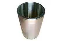
Main Shaft Protective Sleeve Identification Figures
04

Main Shaft Protective Sleeve

Mainshaft Protective Sleeve

Mounting Main Shaft Externally, it is an independent protection piece that does not equate Main Shaft or Main Shaft Assembly. Contrast the internal and external diameters, length of a doorway to be fitted with each other;

Material Selection: Bases, surface Hardness, heat treatment and the requirements of matching according to original design, not used Main Shaft materials Directly replace.

View Part Details →
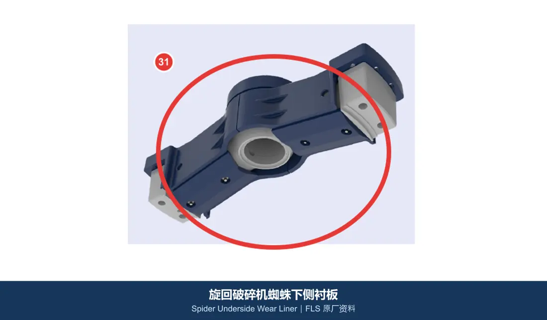
Spider s side liners Identification Figures
05

Spider s side liners

Spider Underside Wear Liner

Protection Spider The surface and adjacent areas are subjected to blasts, rebounding or mineral flows. Contrast the left-hand direction of plate layout with holes in lineage

Material Selection: Manganese steel or quenched and tempered abrasion-resistant plate By impact and sliding wear Proportionally Selected.

View Part Details →
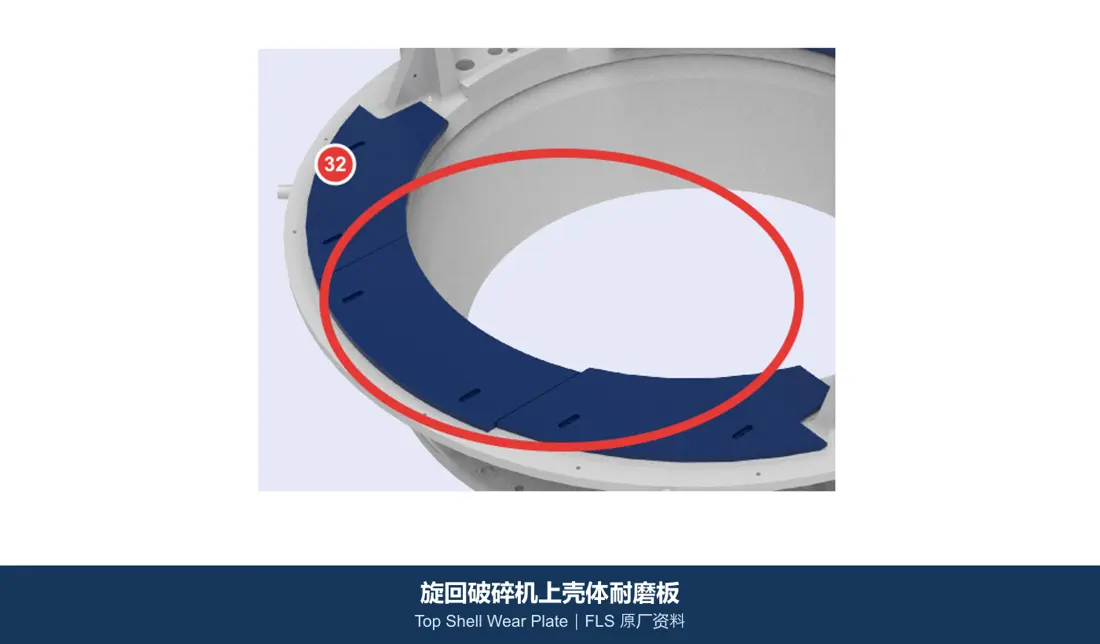
Upper Housing Wear Plate Identification Figures
06

Upper Housing Wear Plate

Top Shell Wear Plate

Protection of protection Housing Feeding and rebound areas. Converged Mounting partitioning, plate thicknesses and arcades; fitting with the connection. Construction and the concave liner Borders.

Material Selection: Quenched and Tempered Wear Plate, high-manganese steel or Composite wear-resistant construction By impact, abrasive wear and Installation Confirmation.

View Part Details →
Spare Parts

Spider Assembly, Main Shaft, Eccentric Bushing, Power Transmission, bearing Hydraulic sealing

General Power Transmission Separately with the loader Identification. Large shafts, external protection bushings, eccentric bushing, gear, bearing and sealing separately check drawing number, materials, Interfaces and co-operation.

Spider Assembly Identification Figures
01

Spider Assembly

Spider Assembly

The whole graph is used Identification Top Spider Location. Consolidation of the total Spider Arms, central girdle and flange connections. bushings The seat and the whole Model No.

Material Selection: Large Cast Steel Or welding Construction, Connectors and Bearings materials Graphics, loads and NDT Requests for confirmation.

View Part Details →
Main Shaft (Big Axes) Identification Figures
02

Main Shaft (Big Axes)

Mainshaft

Main Shaft loaded Core Parts Must be external Main Shaft Protective Sleeve Converged, aligned and matching the necks of axes. Interfaces and test requirements.

Material Selection: Large Forged Alloy Steel, heat treatment axis and neck precision, straightness NDT by complete model Confirmation with the original drawings.

View Part Details →
Pillars bushings With oil seals Identification Figures
03

Pillars bushings With oil seals

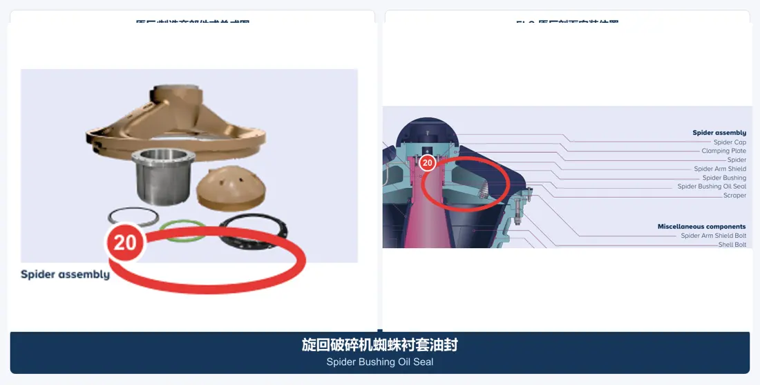
Spider Bearing & Oil Seal

The pivot Main Shaft lubricating and sealing the upper end. Converging axle diameter, bushings Inner and external diameters, flanges / oil sink Construction and sealing form.

Material Selection: Copper Alloys for Bearings Steel fittings and Seal Materials Recognized by load, lubrication and temperature.

View Part Details →
gyratory crusher eccentric bushing General Ideas
04

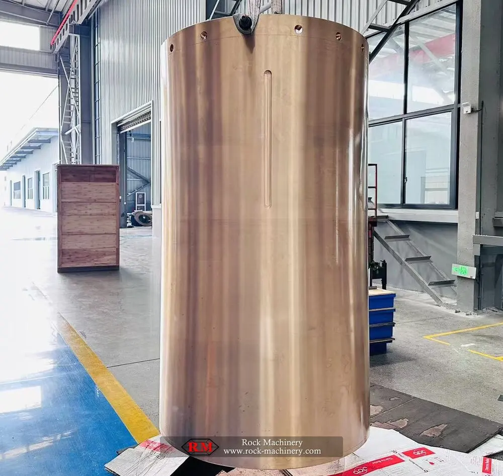
Eccentric Bushing

Eccentric Bushing

In the eccentric body, forming and bearing Main Shaft. Contrast the polarization of distance, internal and external diameters; up-toe direction: oil sinking point Working clearances.

Material Selection: Copper Alloys for Bearings Labels and casting Quality, oil tank and matching gap by loads of the loading. Lubrication with original drawings confirmed

View Part Details →
gyratory crusher Gear Wheel General Ideas
05

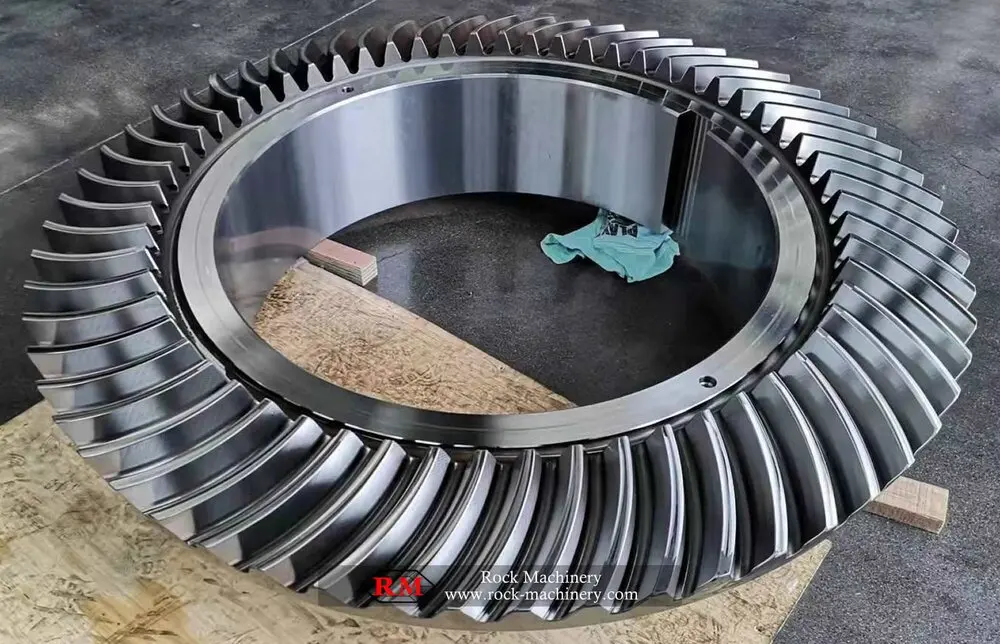
Gear Wheel

Bevel Gear

. Must and pinion The number of pairs, the numbers teeth and pressure angles are paired with a spiral direction; Mounting Distance, side gap and Contact stained.

Material Selection: Carbon permeation or morphology Alloy Steels for Drive Parts Touching the teeth Hardness, core toughness and accuracy of pairing Inspection Confirmed according to the original design.

View Part Details →
pinion Identification Figures
06

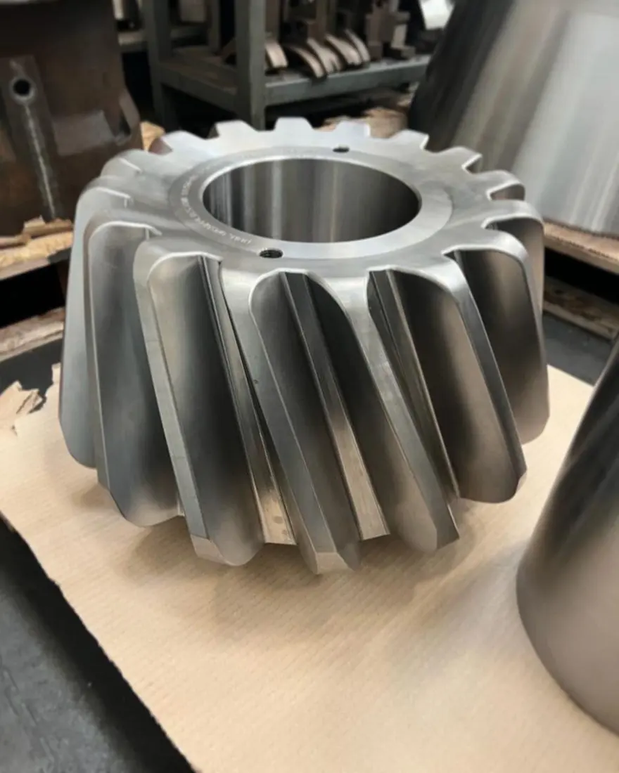
Pinion

Pinion

and Gear Wheel The pairing of horizontal axis power. Converging number, rotational parameters and axes Interfaces, and the record of a pairing.

Material Selection: Forged Alloy Steels for Drive Parts and corresponding heat treatment, by torque and impact loads. Hardness and the sturdyness of your heart.

View Part Details →
Pinion Shaft Bearing Identification Figures
07

Pinion Shaft Bearing

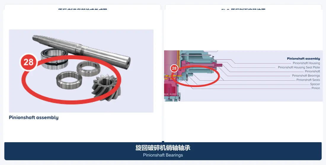
Pinionshaft Bearings

Level of sizing Pinion Shaft and maintain gear The center distance. Convergence bearing model, the gaps and load directions; shaft neckline.

Material Selection: bearing Steel, slab and accessories for the use of materials by Speed, loads and temperature rise as well.

View Part Details →
Pinion Shaft Seal Identification Figures
08

Pinion Shaft Seal

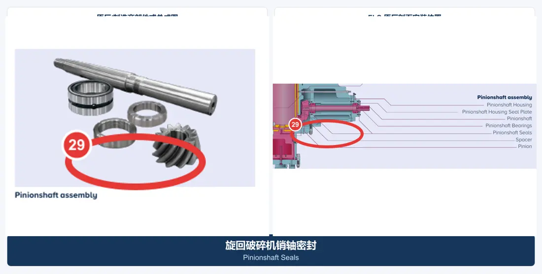
Pinionshaft Seals

Separation of dust and preservation Power Transmission lubricating the box. Converging axle diameter, Refining Grooves lip direction, temperature and oil products. Speed and lids Construction.

Material Selection: NBR, HNBR, FKM, polyurethane or Engineering Seal Materials Recognized by temperature, medium and mode of movement.

View Part Details →
Hydraulic adjustment bushings Identification Figures
09

Hydraulic adjustment bushings

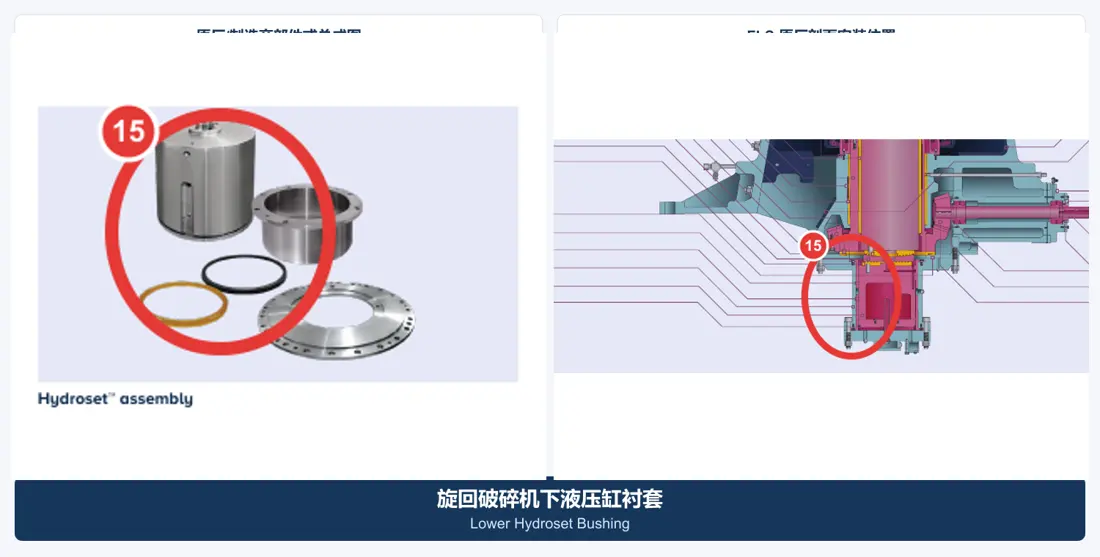
Hydroset Bushings

Hydraulic adjustment and Main Shaft The bearing system: checks up and down position, internal or external diameter of the surface to axe height; oil sinking with gap Interfaces.

Material Selection: Copper Alloys for Bearings Hydraulics and hydraulic Construction Steel parts are confirmed by surface pressure, lubrication and size stability.

View Part Details →
Hydraulic piston seal Identification Figures
10

Hydraulic piston seal

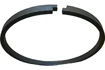
Hydroset Piston Seal

Keep the hydraulic adjustment system pressure and isolate contaminants. Contrast cylinder diameter, rod radius Refining Grooves, pressures and temperature of the medium in combination with sealing directions.

Material Selection: polyurethane, NBR, HNBR, FKM, PTFE or composite seals are confirmed by pressure, medium and temperature.

View Part Details →
Dust Seal System Identification Figures
11

Dust Seal System

Dust Sealing System

Protecting areas of polarity and lube. Contrast seals, Refining Grooves, Contact Surface, sweep or overpressure conditions and supporting dust protection Construction.

Material Selection: elastomers, polyurethane or engineered plastics are confirmed by dust, temperature and oil products as well the relative motion.

View Part Details →
Main Shaft Step Plate Conclusions Identification Figures
12

Main Shaft Step Plate Conclusions

Step Bearing Components

Receivers Main Shaft Axle loads work in conjunction with hydraulic adjustment systems. Converging the order, Contact Diameter, oil film gap and assembly height.

Material Selection: Wear-Resistant Alloy Steel and Copper Alloys for Bearings Confirm by surface pressure, lubrication and flatness requirements.

View Part Details →
Drawing and Spare Part Numbers

PXZ drawing number and third parties spare parts Node Confirmation Entry

Available publicly available information has not been compiled and can be traced by item PXZ model, installation position and Drawing Revision part number Tables, therefore not computed number in the page.

Selection Guidelines: Only posting can be traced back to specific model, installation position and the original base number; OEM drawing number With third parties spare parts The column records, not mixed and uncounted.

PXZ model Can the two numbers be directly represented? parts Dimensions?

Cannot.They are used Identification Names of host Series, not parts Manufacturing Sizes; parts Reconciliation is still required drawing number, Drawing Revision, installation position and practical Interfaces.

Main Shaft and Main Shaft Protective Sleeve Is it the same? parts ?

No. Main Shaft loaded Core Parts, Main Shaft Protective Sleeve y Mounting Main Shaft Externally independent protective parts, the two are matched by size. materials and drawing number.

No public drawing number Can I confirm PXZ spare parts ?

Complete model, project nameplates and equipment general arrangement drawing / installation position can be submitted first to determine the identification of used parts (image), drawings or key dimensions.

Submission CITIC Heavy Industries PXZ model, drawing number, Liners scattering or spare parts Demand

Provide complete model, serial number / OEM or third party numbers and drawings of used parts (materials) with photons for the operation conditions that we will then perform part identification; material assessment.

Manufacturing Services in China

From Technical Assessment to Finished-Part Delivery

ANRANST provides customers worldwide with coordinated consulting, supplier sourcing, quality control and finished-part delivery for custom parts, wear parts and industrial spares from China, with scope to support other custom industrial parts.

01

Technical Advice

Equipment and part identification, drawing review, material selection and manufacturing feasibility assessment.

02

Supplier Introductions

Match requirements with suitable manufacturers in China and coordinate the exchange of technical information.

03

Quality Control

Drawing confirmation, material and process control, production tracking, inspection and acceptance coordination.

04

Finished-Part Delivery

Coordinate manufacturing, quality confirmation, packaging and delivery of complete finished parts.

Provide the existing model, drawings, drawing or part numbers, materials or operating conditions so we can identify the appropriate technical review and supply route.

Submit an Enquiry