
01
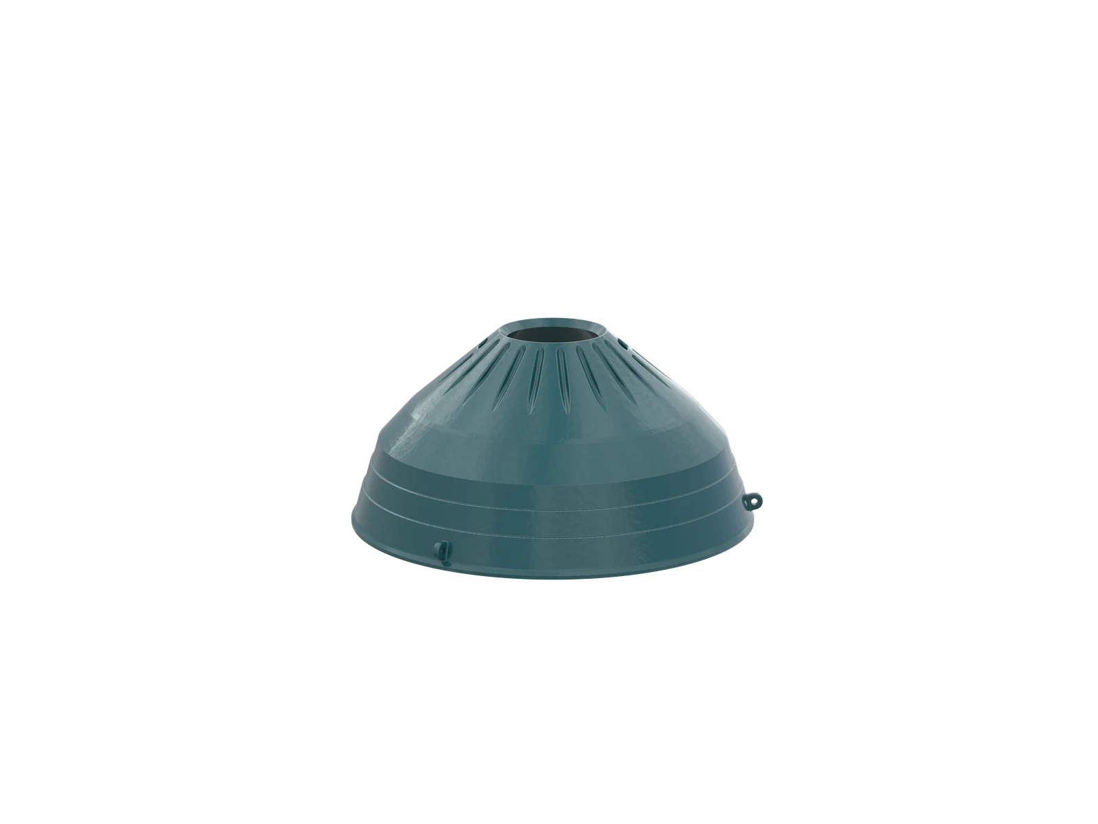
Mantle
Mantle / Head Liner
Fits on the crusher head and moves eccentrically, forming the chamber with the concave. Check chamber type, profile, head interface, backing gap and discharge setting.
View Part Details →Use the CCS / CC series, complete nameplate and chamber configuration to identify mantles, concaves, frame wear parts, copper-alloy bushings, locking components and hydraulics for enquiry.
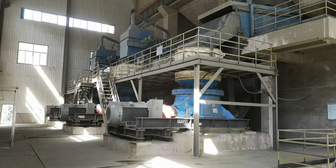
CCS is the single-cylinder hydraulic cone crusher series; CC is the multi-cylinder hydraulic cone crusher series. Identify wear parts and spare parts by complete model, chamber, serial number and installation drawings.
Provide the nameplate, complete model, chamber type or equipment drawings to confirm maximum feed size, discharge setting, capacity, power and the corresponding parts.
| Equipment Series | Complete Model | Key Identification Details | Required Checks Before Manufacturing |
|---|---|---|---|
| CCS Series | Confirm Against the Installed Machine Nameplate | Machine specification, chamber type, mantle and concave profiles | Serial number, general arrangement, drawing, revision and installation position |
| CC Series | Confirm Against the Installed Machine Nameplate | Machine specification, chamber type, eccentric and bearing arrangements | Serial number, general arrangement, drawing, revision and installation position |
The numbers on the diagram correspond one to one with the rows below.
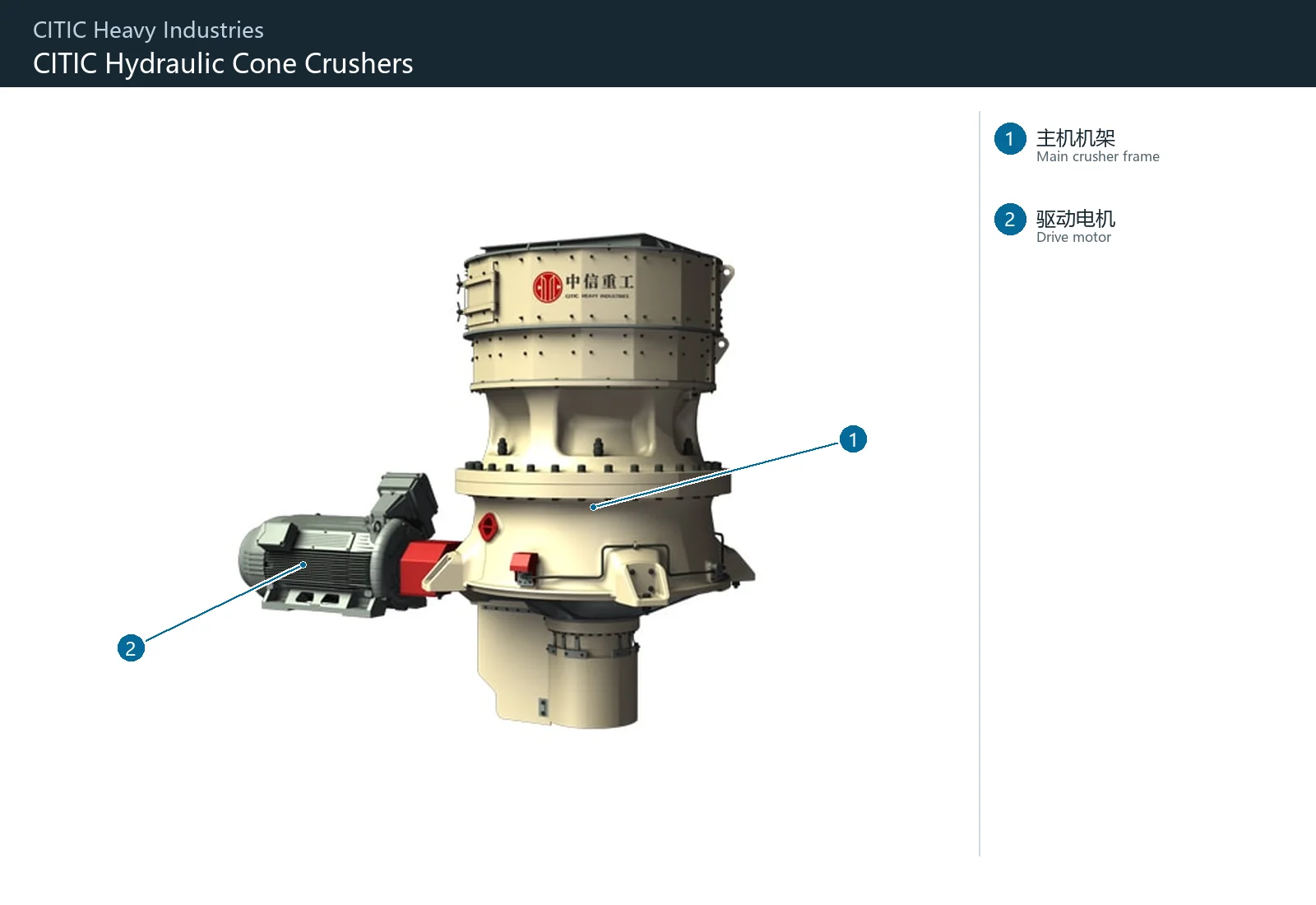
| No. | Component | Location | Applies to |
|---|---|---|---|
| 1 | Main crusher frame | Beige main crusher frame | CCS single-cylinder cone crusher family |
| 2 | Drive motor | Electric drive motor on the left | CCS single-cylinder cone crusher family |
Start with mantles and concaves. Select materials for the chamber, feed, impact loads, ore hardness, wear zones and site wear-life records.
Mantle / Head Liner
Fits on the crusher head and moves eccentrically, forming the chamber with the concave. Check chamber type, profile, head interface, backing gap and discharge setting.
View Part Details →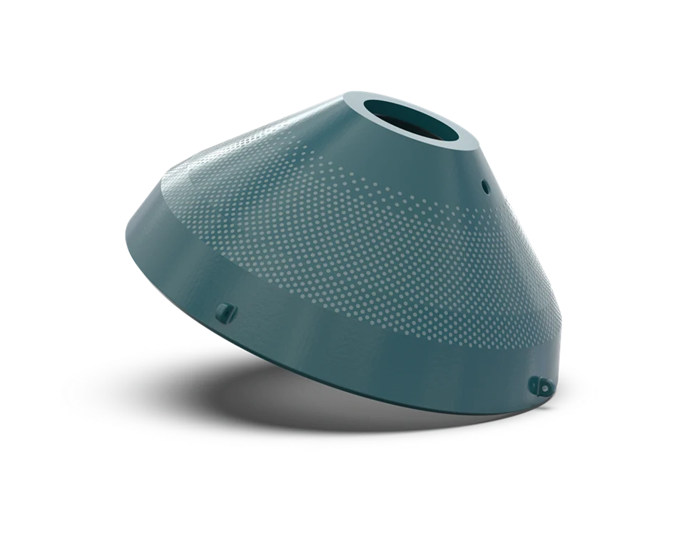
Concave / Bowl Liner
Secured in the upper shell or adjustment ring to form the specified chamber with the mantle. Check chamber type, angle, seating surfaces, locking arrangement and wear profile.
View Part Details →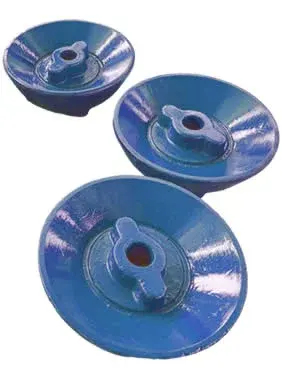
Feed Plate / Feed Cone
Located at the top of the crusher to distribute feed and protect the head area. Check outside diameter, centre hole, conical surface, fastening, rotation direction and feed landing point.
View Part Details →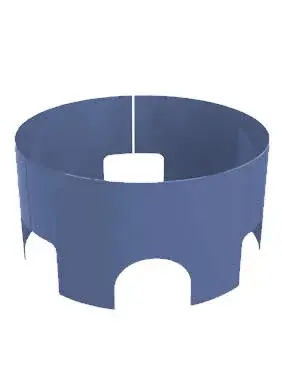
Mainframe Liner
Protects frame areas exposed to falling material, rebound and dust abrasion. Check segmentation, curvature, openings, thickness, hole pattern and drive-side clearance.
View Part Details →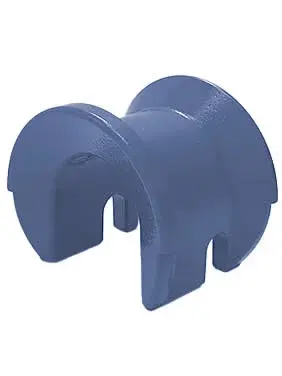
Arm Guard / Arm Liner
Protects the frame arms and areas near the discharge passages. Check quantity, orientation, profile, thickness, hole pattern and installation zones.
View Part Details →Check bearing and hydraulic parts individually by complete model, orientation, interface, fit, tolerance, oil grooves, material and pressure conditions.
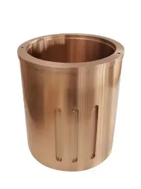
Eccentric Bushing
Located in the eccentric mechanism and contributing to the head motion. Check eccentricity, inside and outside diameters, upper and lower orientation, oil grooves, locating registers, fits and running clearance.
View Part Details →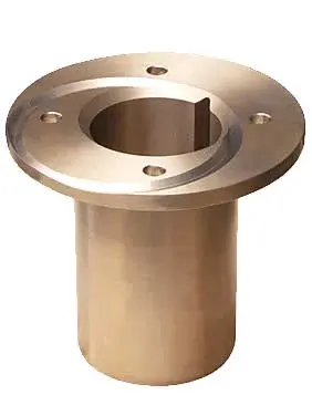
Countershaft Bushing
Supports the countershaft and maintains gear centre distance. Check shaft diameter, housing bore, length, flange, oil grooves, fit and lubrication method.
View Part Details →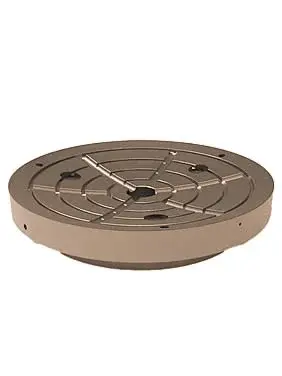
Socket Liner
Supports the crusher head and allows it to gyrate. Check spherical radius, internal and external profiles, oil grooves, contact pattern, clearance and assembly orientation.
View Part Details →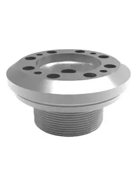
Locking Nut
Secures the mantle or associated head components. Check thread specification, handedness, end face, locking arrangement, mating parts and assembly or removal method.
View Part Details →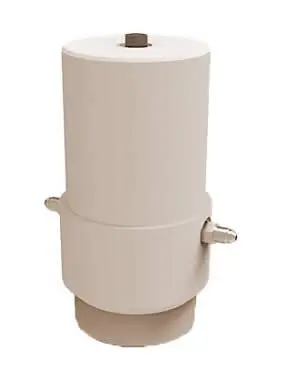
Clamping Cylinder Assembly
Used in adjustment or locking mechanisms. Check bore, stroke, mounting interfaces, oil ports, pressure, seal arrangement and crusher configuration.
View Part Details →Provide the complete nameplate, serial number, general arrangement drawing or project equipment documents, and check the crushing chamber, part position and drawing revision.
No. Also confirm the complete model, chamber type, profile, seating surfaces, locking arrangement, discharge setting, backing, material and drawing revision.
Submit the nameplate, general arrangement drawing, installation position, used part photographs, chamber details and critical dimensions. These help assess identification, dimensional survey and manufacturing to drawing.
Provide the complete model, serial number, drawings, used part photographs, material and operating conditions. We use these to identify parts, assess materials, arrange production at certified foundries to the customer technical requirements, control quality and deliver finished products.
Or contact us directly: +86 156 3797 3199
zzx@anranst.com
ANRANST provides customers worldwide with engineering assessment, production at certified foundries to the customer technical requirements, quality control and finished-part delivery for custom wear parts and industrial spares, with scope to support other custom industrial parts.
We review mating surfaces and interface dimensions and assess material, heat treatment and manufacturing feasibility.
Material grades and heat-treatment processes are specified order by order, stated in the technical agreement and tracked through production.
Drawing confirmation, material and process control, production tracking, inspection and acceptance coordination.
We coordinate manufacturing, quality confirmation, packaging and delivery of complete finished parts in a workable, closed-loop supply process.
Provide the equipment brand, complete model and serial number, part name, part number or drawing number, drawing revision, quantity, material requirements and duty. If identifiers are unavailable, send photographs and key dimensions.
Submit an Enquiry