CITIC HIC Jaw Crusher

Start with the PE Series, complete nameplate and feed-opening dimensions, then identify jaw and cheek-plate wear systems, toggle plate, eccentric shaft, bearings, wedges, seals and inquiry requirements.

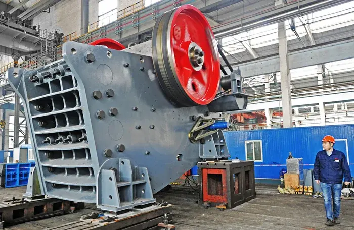
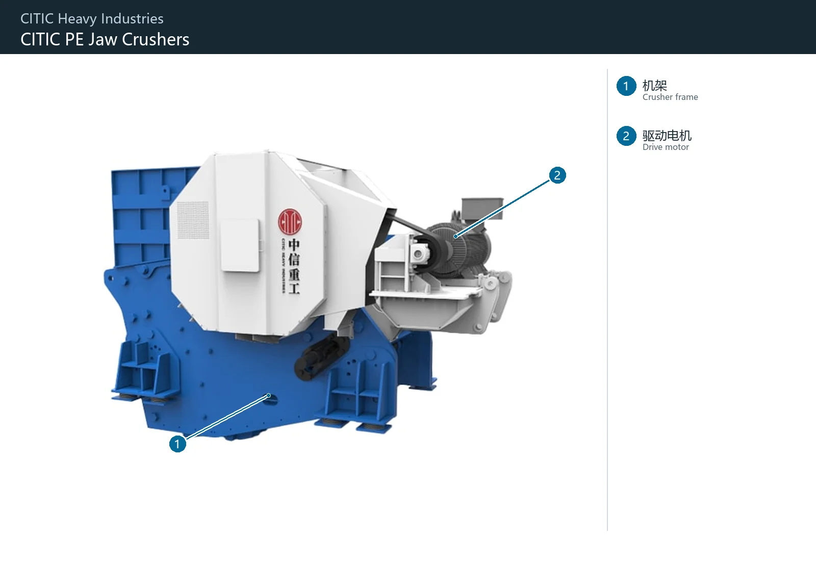
Official CITIC HIC jaw crusher product image
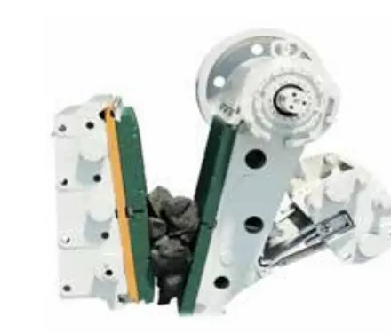
Official CITIC HIC jaw crusher product image. Confirm the installed machine from the complete model, feed-opening dimensions, project nameplate and equipment documentation.
OEM Equipment Details

Installed-Equipment Identification, Wear Parts and Spares on One Page

CITIC HIC's current public product catalogue confirms the jaw crusher category but does not provide a complete model specification table. This page therefore uses the series, key identification information and linked parts without inferring specifications.

PE Published Product Series
6 Core Wear Parts
8 Structural and Drive Spares
1 Technical Enquiry
Standard Models and Key Dimensions

PE Series and Installed-Equipment Identification Fields

The public catalogue confirms the product series. Use the nameplate, complete model or equipment drawings to establish feed and discharge openings, power, capacity and part relationships for the installed machine.

Equipment SeriesComplete ModelKey dimensionsRequired Checks Before Manufacturing
PE SeriesConfirm Against the Installed Machine NameplateFeed Opening Width × Length and Discharge-Opening RangeSerial number, general arrangement, jaw-tooth profile, installation direction and drawing revision

Generic PE models used in the third-party market are not assigned to CITIC HIC installed equipment. Confirm a model from the nameplate, OEM catalogue or project documentation.

Wear Parts

Jaw Plates, Cheek Plates and Crushing-Chamber Wear Parts

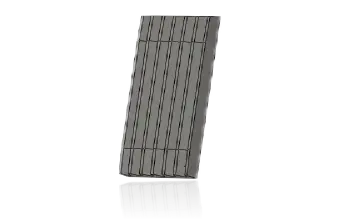
Fixed and moving jaw plates and upper/lower cheek plates are presented first. Material selection must consider tooth profile, impact, abrasive wear, work hardening and site service-life records.

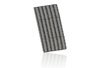
Fixed jaw plate identification image
01

Fixed Jaw Plates

Fixed Jaw Plate

Installed on the fixed-jaw side to form the crushing chamber with the moving jaw plate. Confirm tooth profile, top/bottom orientation, width, thickness, mounting grooves, hole pattern and actual wear profile.

Material Selection: High-manganese steel is the main candidate. Ore hardness, lump size, impact and the degree of work hardening determine the specific grade and process.

View Part Details →
Moving jaw plate identification image
02

Movable Jaw Plate

Movable / Swing Jaw Plate

Moves with the pitman and resists compression, impact and sliding wear. Confirm tooth-profile direction, upper/lower location, mounting grooves, thickness and matched relationship with the fixed jaw plate.

Material Selection: Use high-manganese steel or duty-validated alloyed high-manganese steel. Confirm material and heat treatment according to feed, impact and wear zones.

View Part Details →
Upper cheek plate identification image
03

Upper Cheek Plate

Upper Cheek Plate

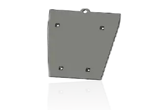
Protects the upper sidewall of the crushing chamber against feed impact and lateral wear. Confirm left/right orientation, hole spacing, thickness, overlap and boundary with the jaw plates.

Material Selection: Confirm quenched-and-tempered wear plate, high-manganese steel or alloy steel according to the ratio of impact to sliding wear.

View Part Details →
Lower cheek plate identification image
04

Lower Cheek Plate

Lower Cheek Plate

Protects the lower sidewall of the crushing chamber, often in a zone of concentrated compression and abrasive wear. Confirm left/right orientation, hole pattern, thickness and boundary at the discharge opening.

Material Selection: Confirm quenched-and-tempered wear plate, high-manganese steel or special alloy according to abrasive wear, impact and replacement interval.

View Part Details →
Intermediate plate identification image
05

Intermediate Plates

Intermediate Plate

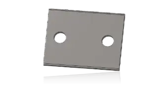
Used at a mounting or protection position for specific chamber and jaw-plate combinations. Confirm whether it is fitted, its quantity, profile and hole pattern from the machine drawings.

Material Selection: Confirm high-manganese steel or wear-resistant alloy steel according to installation position, load and original design.

View Part Details →
Toggle plate identification image
06

Toggle Plates

Toggle Plate

Located in the pitman load-transfer mechanism and serving both load-transfer and overload-protection functions. Confirm length, thickness, end radius, seating surfaces, working direction and matching toggle seats.

Material Selection: Confirm structural or cast-steel strength and the intended protection characteristic against the original design; external shape alone is insufficient.

View Part Details →
Spare Parts

Eccentric Shaft, Bearings, Toggle Mechanism, Wedges and Seal Spares

Confirm general drive and structural parts separately by complete model, direction, interfaces, fits, tolerances, material, heat treatment and inspection requirements.

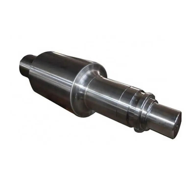
Eccentric-shaft identification image
01

Eccentric Shafts

Eccentric Shaft

Core shaft that drives the pitman's reciprocating motion. Confirm eccentricity, journals, keyways, threads, bearing positions, fits and rotation direction.

Material Selection: Confirm forged transmission-alloy steel, heat treatment, journal hardness, straightness and nondestructive testing from the original drawings.

View Part Details →
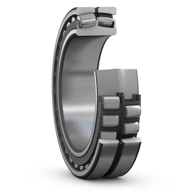
Spherical roller bearing identification image
02

Spherical Roller Bearings

Spherical Roller Bearing

Supports the eccentric shaft under radial and impact loads. Confirm the complete bearing designation, clearance, cage, journal, housing bore, tolerances and lubrication method.

Material Selection: Use the bearing to the original specification. Confirm bearing housing and mating shaft parts according to load, temperature rise and fits.

View Part Details →
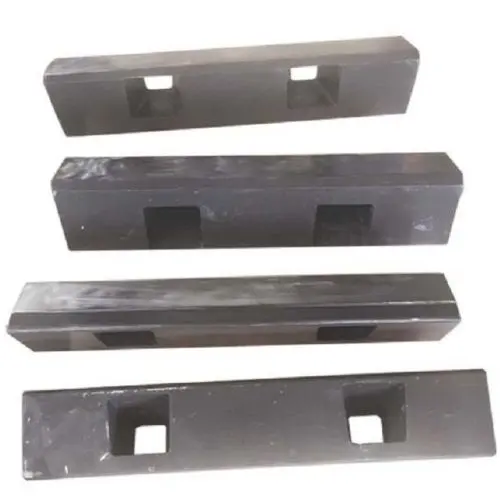
Jaw-plate tightening wedge identification image
03

Jaw-Plate Tightening Wedge

Jaw Die Clamping Wedge

Secures the jaw plate in its installed position. Confirm upper/lower position, orientation, inclined face, hole pattern, fasteners and interface with the matching jaw plate.

Material Selection: Confirm high-strength alloy steel or cast steel according to clamping load, contact surfaces and original-design heat treatment.

View Part Details →
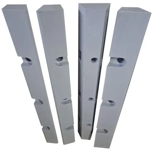
Adjustment-wedge identification image
04

Adjustment Wedge

CSS Adjustment Wedge

Used in the discharge-setting adjustment and associated support mechanism. Confirm wedge angle, thickness, sliding surfaces, left/right orientation, hydraulic or mechanical interface and matching seat.

Material Selection: Confirm quenched-and-tempered alloy steel, surface treatment and sliding fit according to load, adjustment frequency and original drawings.

View Part Details →
Tension-rod identification image
05

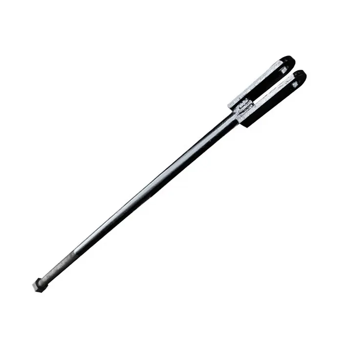
Tension Rods

Tension Rod

Maintains the toggle mechanism and pitman return condition. Confirm length, diameter, thread, end construction, preload and matching spring.

Material Selection: Confirm high-strength structural or alloy steel according to tensile load, fatigue and thread requirements.

View Part Details →
Tension-spring identification image
06

Tension Spring

Tension Spring

Works with the tension rod to maintain return and preload. Confirm outside diameter, wire diameter, free length, coil count, end form and working load.

Material Selection: Confirm spring-steel grade, heat treatment, surface treatment and fatigue life from the original design.

View Part Details →
Labyrinth dust-seal identification image
07

Labyrinth Dust Seal

Labyrinth Dust Seal

Protects bearings and moving areas by limiting dust ingress. Confirm inner and outer rings, clearance, direction, shaft diameter, end cover and lubrication arrangement.

Material Selection: Confirm steel, aluminium alloy, engineering polymer or elastomer seal combinations according to temperature, dust and relative movement.

View Part Details →
Pitman and front casting protection-plate identification image
08

Pitman and Front Casting Protection Plate

Pitman & Front Casting Protection Plate

Protects wear and impact zones on the pitman and front casting. Confirm installation zone, profile, thickness, hole pattern and boundary with adjacent jaw plates.

Material Selection: Confirm quenched-and-tempered wear plate or high-manganese steel according to impact, abrasive wear, welding and installation method.

View Part Details →
Drawing and Spare Part Numbers

Jaw Crusher Drawing Number and Third-Party Part Number Check

CITIC HIC jaw crusher part numbers must be confirmed against the complete model, installation position and drawing revision. Numbers are not inferred on this page.

Selection Guidelines: Part numbers must match the model, installation position and installed-equipment drawings. OEM drawing numbers and third-party part numbers are checked separately.

Why does this page not list a generic set of PE model numbers?

PE model names commonly used in the third-party market do not automatically establish CITIC HIC installed equipment. Confirm models from a nameplate, OEM catalogue or project documentation.

Can fixed and moving jaw plates be matched by external shape alone?

No. Confirm the complete model, tooth profile, top/bottom orientation, mounting grooves, thickness, hole pattern, crushing-chamber relationship, material and drawing revision.

How can parts be identified without a drawing number?

Submit the nameplate, equipment general arrangement, installation position, used-part photographs, jaw-tooth profile and key dimensions to assess identification, reverse engineering and drawing-based manufacturing requirements.

Submit the CITIC HIC jaw crusher model, drawing number, jaw-tooth profile or spare-part requirement

Provide the complete model, serial number, drawings, used part photographs, material and operating conditions. We use these to identify parts, assess materials, select manufacturing resources, control quality and deliver finished products.

Manufacturing Services in China

From Technical Assessment to Finished-Part Delivery

ANRANST provides customers worldwide with coordinated consulting, supplier sourcing, quality control and finished-part delivery for custom parts, wear parts and industrial spares from China, with scope to support other custom industrial parts.

01

Technical Advice

Equipment and part identification, drawing review, material selection and manufacturing feasibility assessment.

02

Supplier Introductions

Match requirements with suitable manufacturers in China and coordinate the exchange of technical information.

03

Quality Control

Drawing confirmation, material and process control, production tracking, inspection and acceptance coordination.

04

Finished-Part Delivery

Coordinate manufacturing, quality confirmation, packaging and delivery of complete finished parts.

Provide the existing model, drawings, drawing or part numbers, materials or operating conditions so we can identify the appropriate technical review and supply route.

Submit an Enquiry