
01
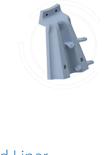
Feed Throat Liner
Throat Liner
Protects the feed throat from ore impact, abrasion and slurry erosion. Check inside and outside diameters, length, flange, hole pattern, rotation direction and feed interface.
View Part Details →Use the AG nominal diameter and project shell dimensions to identify feed, shell, head and discharge liner systems, gearing, materials and drawing for enquiry.
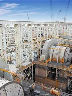
Identify the installation by AG nominal diameter series and project shell dimensions, then confirm liner layout, discharge construction, drive configuration, material and drawing revision.
The model suffix identifies nominal shell diameter. Mill length, drive, discharge and liner layout vary by project.
| Model Series | Nominal Shell Diameter | Shell Length | Required Checks Before Manufacturing |
|---|---|---|---|
| AG-40 | 4,000 mm | Confirm against the mill shell length for the project | Nameplate, general arrangement, discharge and drive configuration |
| AG-50 | 5,000 mm | Confirm against the mill shell length for the project | Nameplate, general arrangement, discharge and drive configuration |
| AG-61 | 6,100 mm | Confirm against the mill shell length for the project | Nameplate, general arrangement, discharge and drive configuration |
| AG-73 | 7,300 mm | Confirm against the mill shell length for the project | Nameplate, general arrangement, discharge and drive configuration |
| AG-80 | 8,000 mm | Confirm against the mill shell length for the project | Nameplate, general arrangement, discharge and drive configuration |
| AG-92 | 9,200 mm | Confirm against the mill shell length for the project | Nameplate, general arrangement, discharge and drive configuration |
| AG-104 | 10,400 mm | Confirm against the mill shell length for the project | Nameplate, general arrangement, discharge and drive configuration |
| AG-110 | 11,000 mm | Confirm against the mill shell length for the project | Nameplate, general arrangement, discharge and drive configuration |
| AG-122 | 12,200 mm | Confirm against the mill shell length for the project | Project, nameplate, general arrangement and gearless drive configuration |
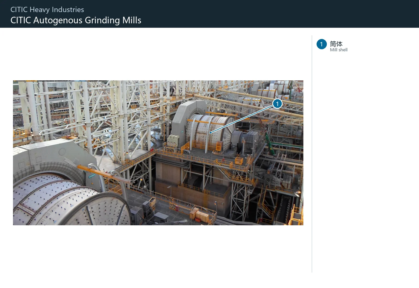
The numbers on the diagram correspond one to one with the rows below.
| No. | Component | Location | Applies to |
|---|---|---|---|
| 1 | Mill shell | Bolted shell of the gearless mill at the right of the Sino Iron photograph | Sino Iron project AG Ø12.2×11m, 28MW gearless drive |
Each position has different impact, abrasion, slurry erosion and material processing requirements. Follow the links to the relevant parts and materials.
Throat Liner
Protects the feed throat from ore impact, abrasion and slurry erosion. Check inside and outside diameters, length, flange, hole pattern, rotation direction and feed interface.
View Part Details →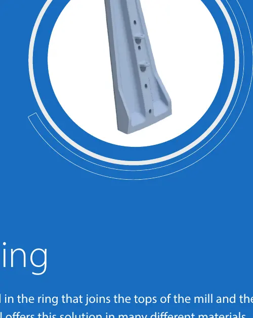
Outer Feed Head Liner
Protects the outer ring and transition area of the feed head. Check segmentation, curvature, radial position, hole pattern, lifter interfaces and rotation direction.
View Part Details →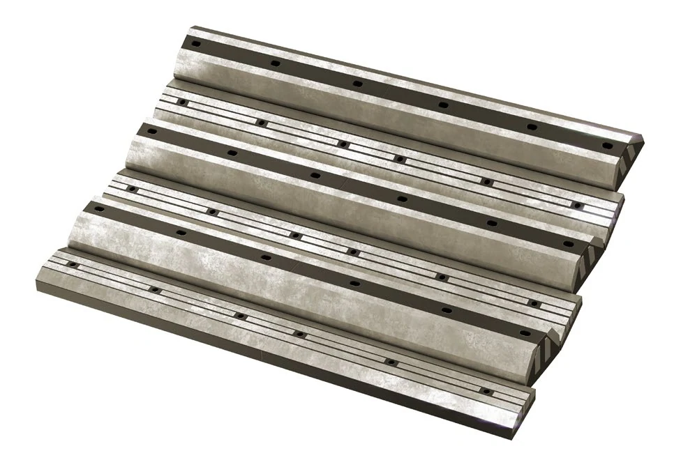
Shell Lifter Plate
Lifts ore and controls its trajectory as part of the AG mill wear system. Check layout, lifter height, profile, hole spacing, shell diameter and rotation direction.
View Part Details →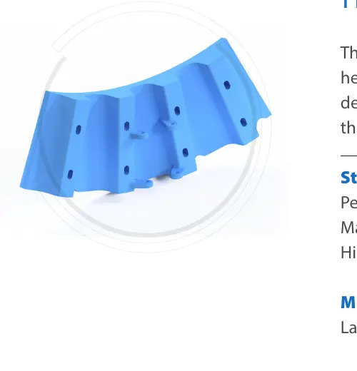
Inner Head Liner
Protects the inner head ring and interfaces with the throat, grates or pulp lifters. Check radial position, curvature, segmentation, hole pattern, rotation direction and adjacent interfaces.
View Part Details →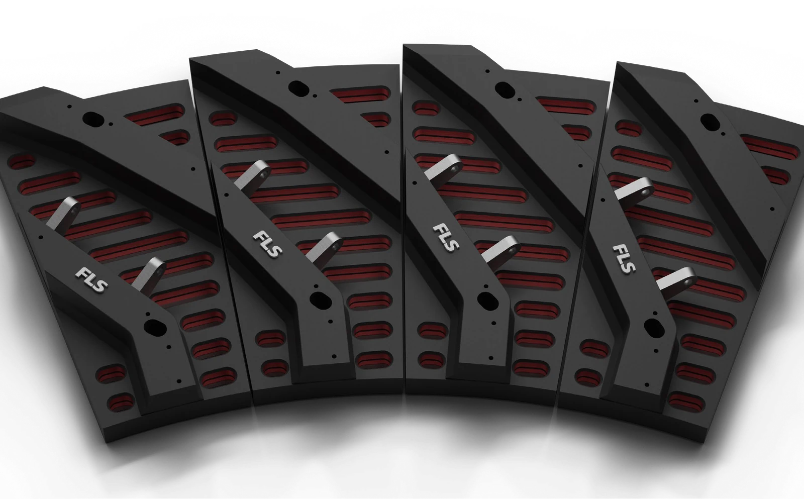
Discharge Grate
Controls passage of slurry and correctly sized particles. Check aperture design, open area, segmentation, curvature, hole pattern, rotation direction, blockage and wear records.
View Part Details →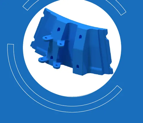
Middle Liner
Fits in a transition zone of the head or discharge system. Check installation level, inner or outer ring, curvature, segmentation, hole pattern and relationship to adjacent pulp lifters.
View Part Details →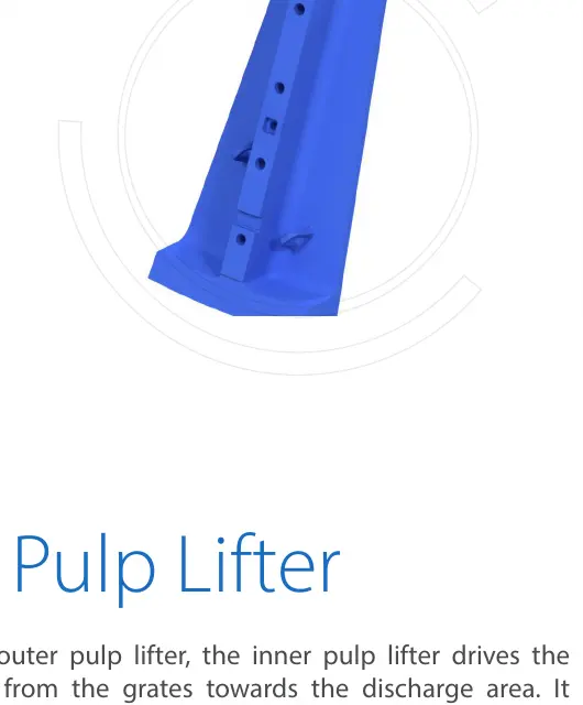
Pulp Lifter
Directs slurry passing through the grates towards discharge. Check inner or outer ring position, vane direction, passage area, rotation direction, hole pattern and blockage records.
View Part Details →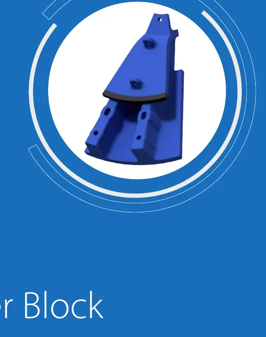
Discharge Cone
Guides slurry from the pulp lifters to the outlet. Check cone angle, inside and outside diameters, length, flange, hole pattern, rotation direction and discharge interface.
View Part Details →Check geared installations against the complete project configuration. Gearless drives do not use the girth gear and pinion arrangement.
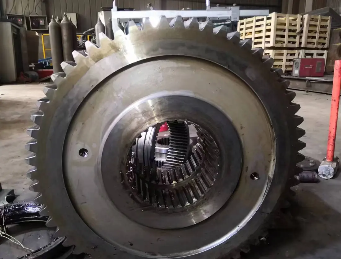
Girth Gear / Ring Gear
Meshes with the pinion to transmit main drive power. Check module, tooth count, pressure angle, helix angle, split joints, mounting distance and contact pattern.
View Part Details →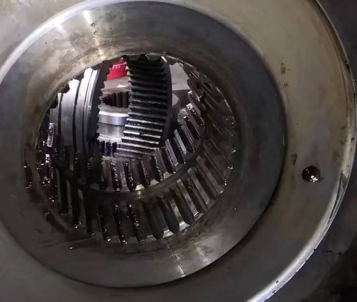
Pinion
Meshes with the girth gear to transmit motor and gearbox output. Check module, tooth count, pressure angle, helix direction, shaft interfaces, backlash and contact pattern.
View Part Details →No. A diameter series may include different project lengths, discharge arrangements, liner layouts and drive types. Check project documents, nameplates and general arrangement drawings.
No. Even with similar shell diameters, confirm mill type, length, layout, profile, hole pattern, lifter height, rotation direction, material and drawing revision.
Submit the nameplate, shell diameter × length, general arrangement, installation position, used part photographs, liner layout and critical dimensions to assess identification, dimensional survey and manufacturing feasibility.
Provide the complete model, shell diameter × length, serial number, liner layout, drawings, used part photographs, materials and duty. We coordinate identification, material assessment, manufacturing selection, quality control and finished part delivery.
Or contact us directly: +86 156 3797 3199
zzx@anranst.com
ANRANST provides customers worldwide with engineering assessment, production at certified foundries to the customer technical requirements, quality control and finished-part delivery for custom wear parts and industrial spares, with scope to support other custom industrial parts.
We review mating surfaces and interface dimensions and assess material, heat treatment and manufacturing feasibility.
Material grades and heat-treatment processes are specified order by order, stated in the technical agreement and tracked through production.
Drawing confirmation, material and process control, production tracking, inspection and acceptance coordination.
We coordinate manufacturing, quality confirmation, packaging and delivery of complete finished parts in a workable, closed-loop supply process.
Provide the equipment brand, complete model and serial number, part name, part number or drawing number, drawing revision, quantity, material requirements and duty. If identifiers are unavailable, send photographs and key dimensions.
Submit an Enquiry