CITIC HIC MQY Overflow Ball Mill

Start with the MQY nominal diameter and project shell dimensions, then identify shell, end and trunnion liners, grinding media, bearing bushes, gear-drive parts, materials, drawing numbers and inquiry requirements.

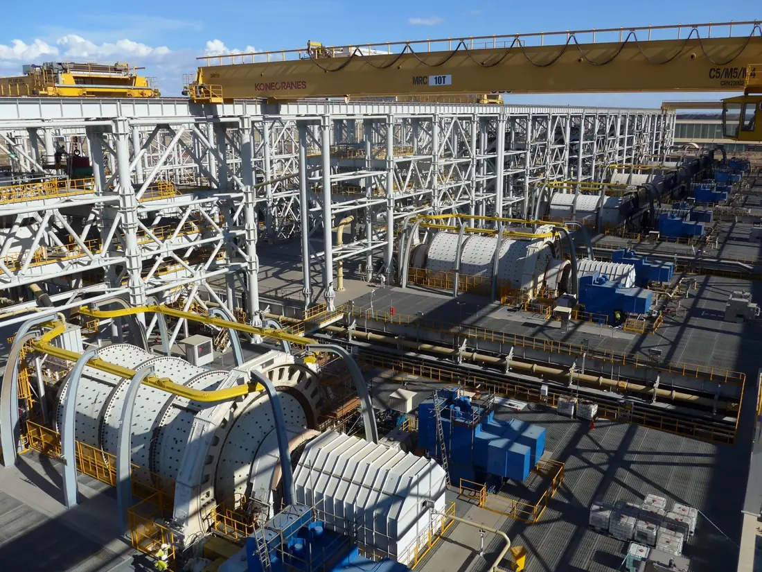
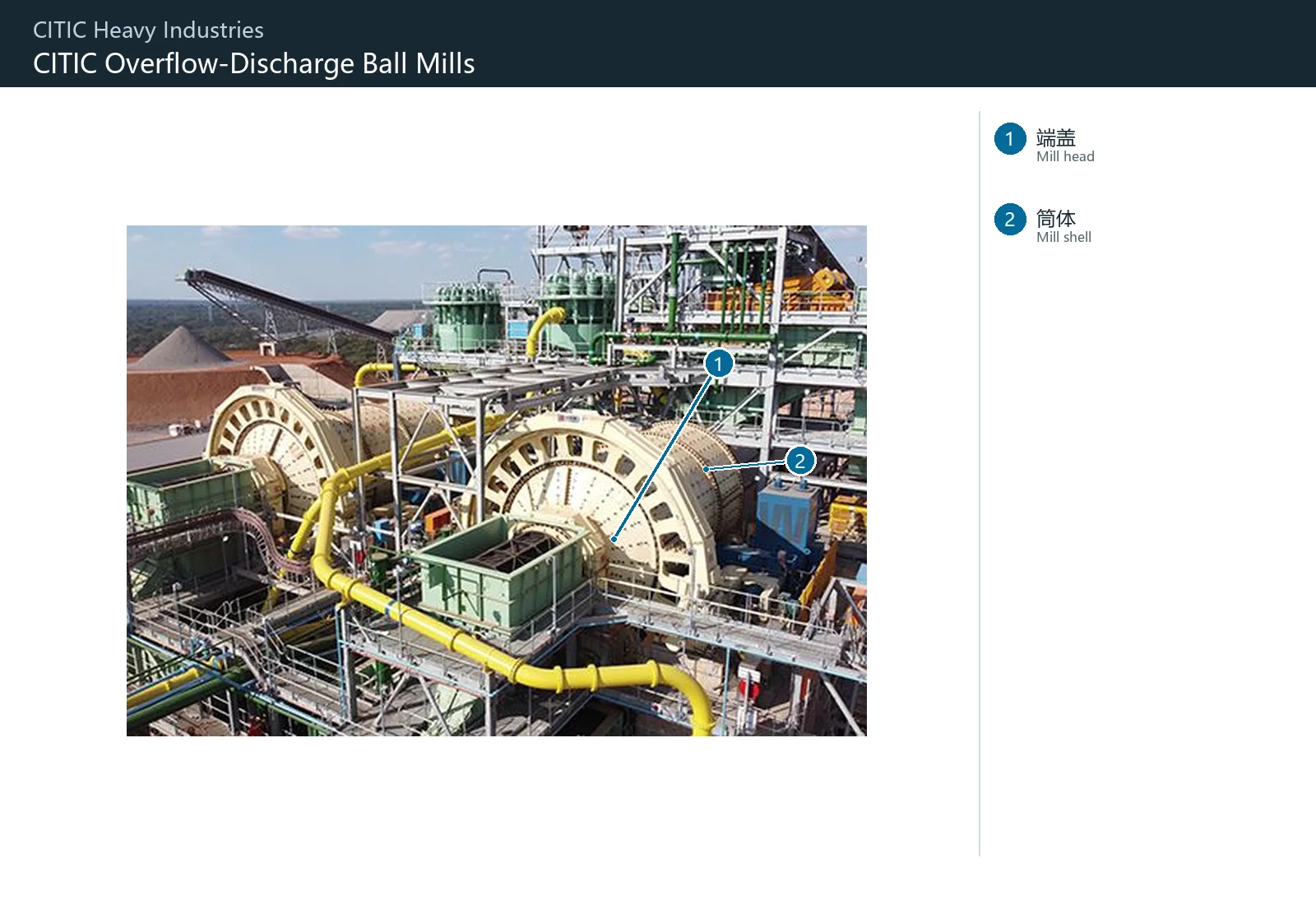
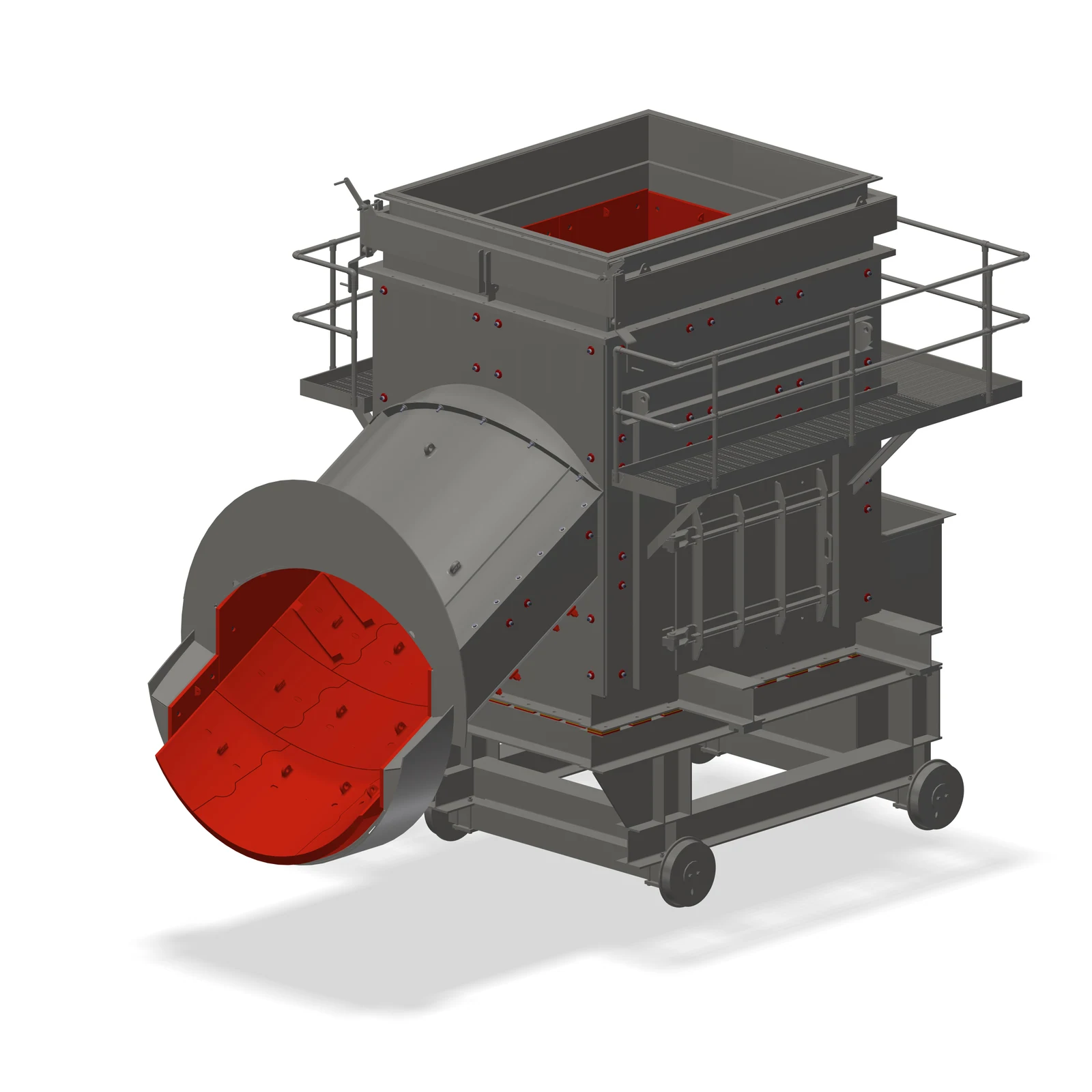
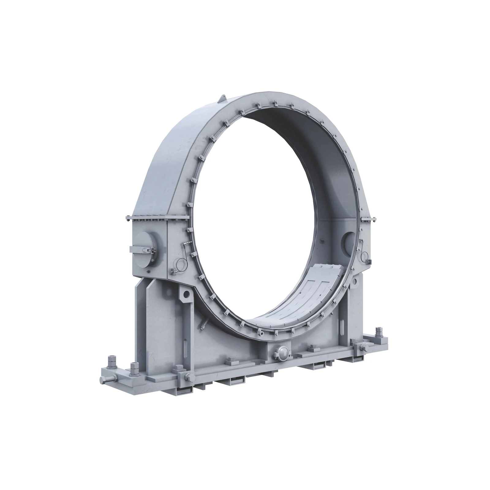
Official CITIC HIC MQY overflow ball mill product image
Official CITIC HIC ball mill product image. Confirm the installed machine from the complete MQY model, shell diameter × length, discharge arrangement, supports and drive configuration.
OEM Equipment Details

Models, Liner Systems and Drive Parts on One Page

This page follows CITIC HIC's published MQY nominal-diameter series and project dimensions. Overflow discharge is not treated as a grate-and-pulp-lifter arrangement.

14 Main Series
1.5–8.8 m Nominal Shell Diameter
6 Wear and Consumable Parts
3 Support and Gear-Drive Parts
Standard Models and Key Dimensions

MQY Series Nominal Diameters and Published Project Dimensions

The model suffix identifies the nominal shell diameter. Length, drive, support and liner arrangement vary by project.

Model SeriesNominal Shell DiameterShell Length / DischargeRequired Checks Before Manufacturing
MQY-151,500 mmConfirm against the mill shell length for the projectNameplate, general arrangement, overflow discharge, supports and drive configuration
MQY-212,100 mmConfirm against the mill shell length for the projectNameplate, general arrangement, overflow discharge, supports and drive configuration
MQY-242,400 mmConfirm against the mill shell length for the projectNameplate, general arrangement, overflow discharge, supports and drive configuration
MQY-303,000 mmConfirm against the mill shell length for the projectNameplate, general arrangement, overflow discharge, supports and drive configuration
MQY-363,600 mmConfirm against the mill shell length for the projectNameplate, general arrangement, overflow discharge, supports and drive configuration
MQY-404,000 mmConfirm against the mill shell length for the projectNameplate, general arrangement, overflow discharge, supports and drive configuration
MQY-454,500 mmConfirm against the mill shell length for the projectNameplate, general arrangement, overflow discharge, supports and drive configuration
MQY-505,000 mmConfirm against the mill shell length for the projectNameplate, general arrangement, overflow discharge, supports and drive configuration
MQY-555,500 mmPublished project dimensions include approximately 8,800 mmProject, nameplate, general arrangement, supports and drive configuration
MQY-606,000 mmPublished project dimensions are approximately 9,750–11,500 mmProject, nameplate, general arrangement, supports and drive configuration
MQY-676,700 mmPublished project dimensions include approximately 9,750 mmProject, nameplate, general arrangement, supports and drive configuration
MQY-737,300 mmPublished project dimensions are approximately 10,680–12,500 mmProject, nameplate, general arrangement, supports and drive configuration
MQY-797,900 mmPublished project dimensions are approximately 13,600–14,330 mmProject, nameplate, general arrangement, supports and drive configuration
MQY-888,800 mmConfirm against the mill shell length for the projectNameplate, general arrangement, overflow discharge, supports and drive configuration

Mills in the same nominal-diameter series may have different shell lengths, supports and drives. Parts are not interchangeable by diameter alone.

Wear Parts

Shell, End, Feed and Trunnion Wear Systems

The MQY overflow ball mill system covers shell liners, lifters, end liners, feed-chute liners, trunnion liners and grinding balls. Grate-discharge-specific parts are excluded.

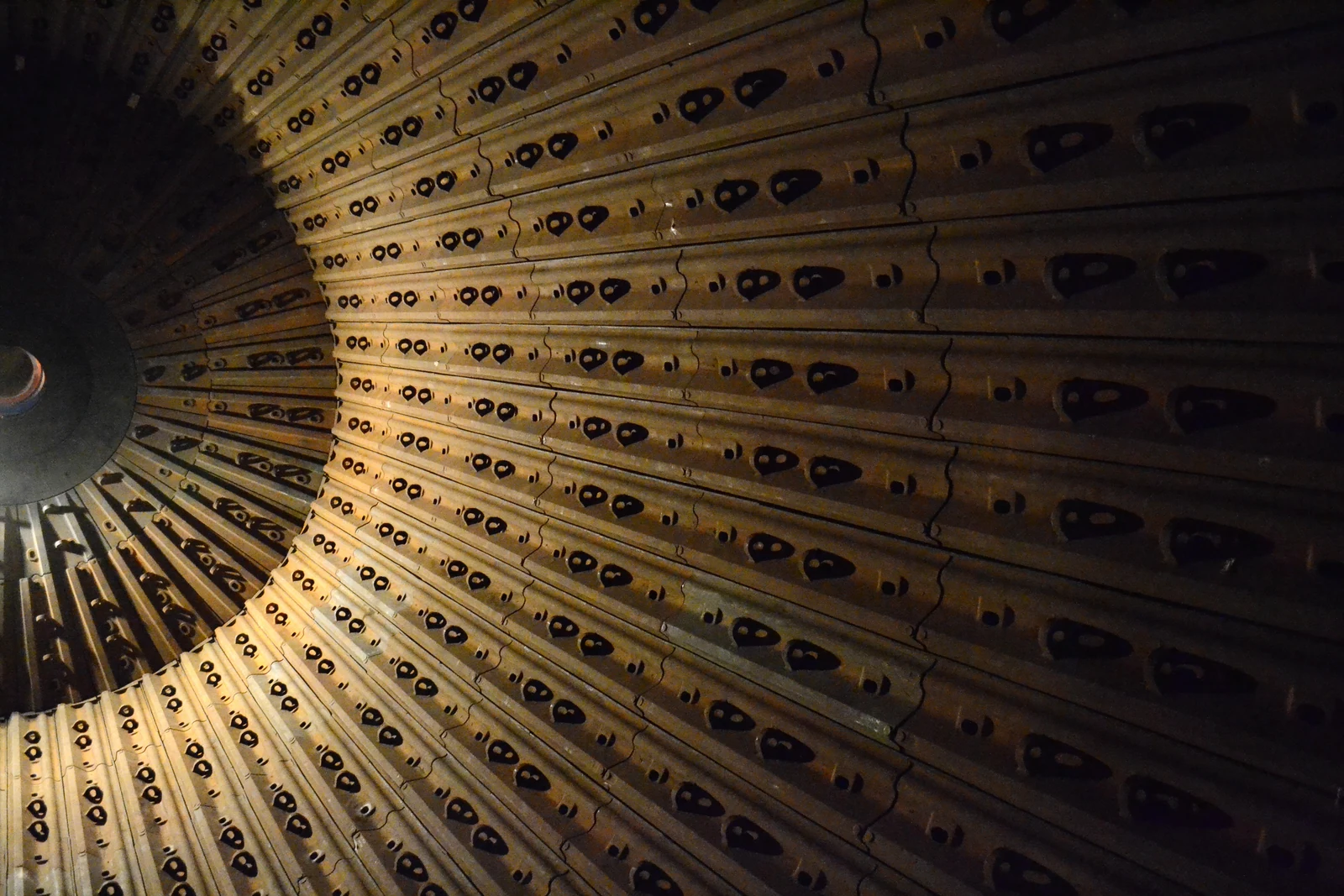
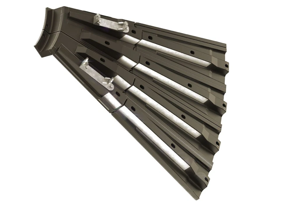
Shell liner identification image
01

Shell Liners

Shell Liner / Shell Plate

Protects the shell interior and works with lifters to control the movement of grinding balls and material. Confirm the arrangement, curvature, thickness, hole spacing, shell diameter, rotation direction and adjacent liners.

Material Selection: Confirm Cr-Mo alloy steel, high-chromium cast iron, rubber or composite liners according to impact, abrasive wear, slurry corrosion and shell zone.

View Part Details →
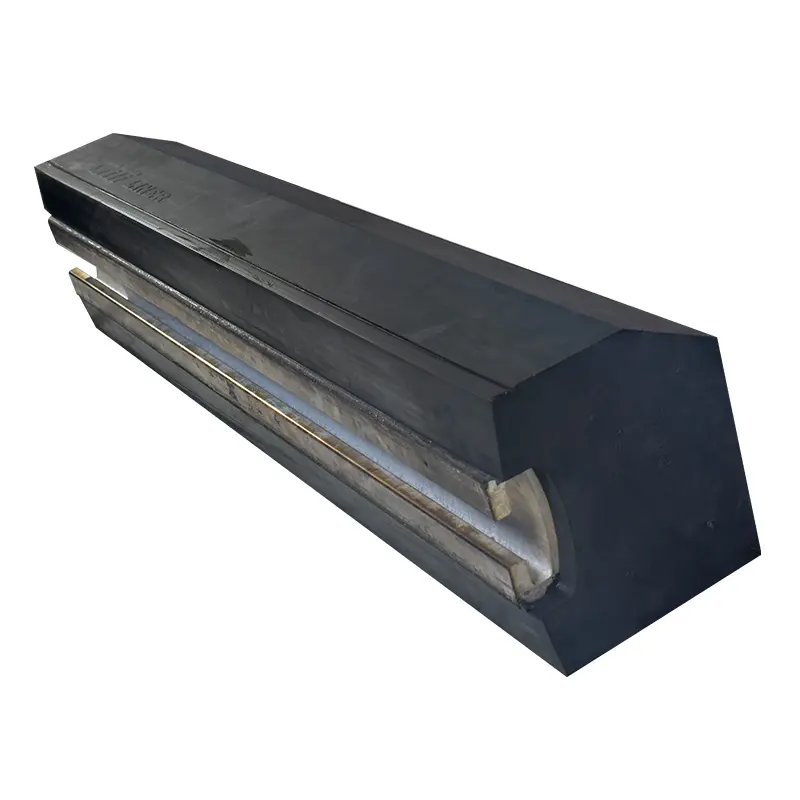
Lifter Bar / Lifter Plate identification image
02

Lifter Bar / Lifter Plate

Lifter Bar / Lifter Plate

Lifts grinding balls and material and controls their trajectory. Confirm lifter height, profile, pitch, arrangement, hole pattern, shell diameter and rotation direction.

Material Selection: Confirm Cr-Mo alloy steel, high-manganese steel, rubber or composite construction according to impact energy, wear zones and service-life target.

View Part Details →
End liner / head liner identification image
03

End Liner / Head Liner

End Liner / Head Liner

Protects the feed-end or discharge-end head. Confirm the end, inner or outer ring, segmentation, curvature, hole pattern, rotation direction and interfaces with the throat or discharge structure.

Material Selection: Confirm Cr-Mo alloy steel, high-manganese steel, high-chromium cast iron or rubber-composite construction according to impact, wear and end stress.

View Part Details →
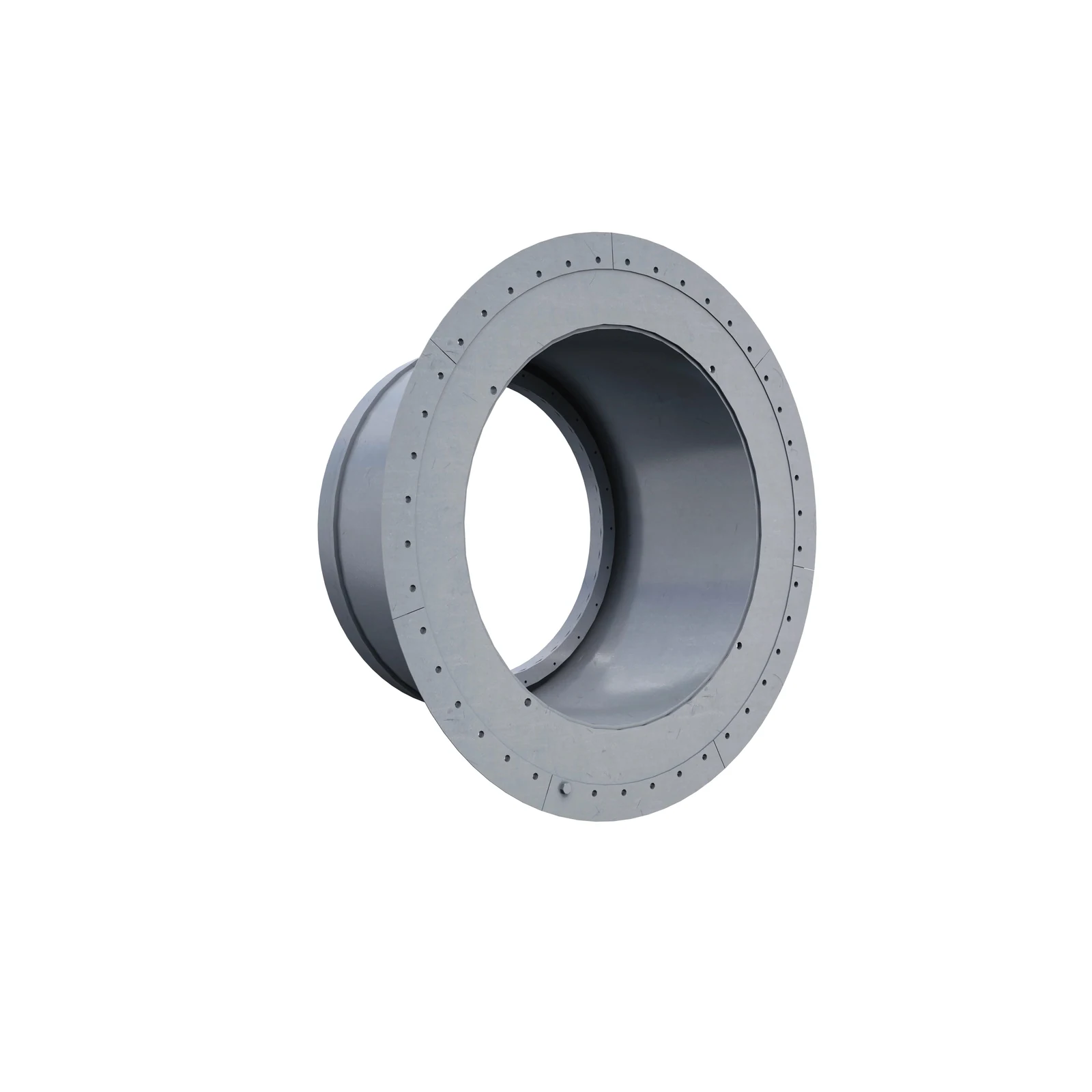
Trunnion liner / journal liner identification image
05

Trunnion Liner / Journal Liner

Mill Trunnion Liner

Protects the inner surface of the feed or discharge trunnion. Confirm the end, inside and outside diameters, length, taper, flange, hole pattern, rotation direction and adjacent structure.

Material Selection: Confirm Cr-Mo alloy steel, high-manganese steel, high-chromium cast iron or rubber-composite construction according to erosion, wear, corrosion and assembly method.

View Part Details →
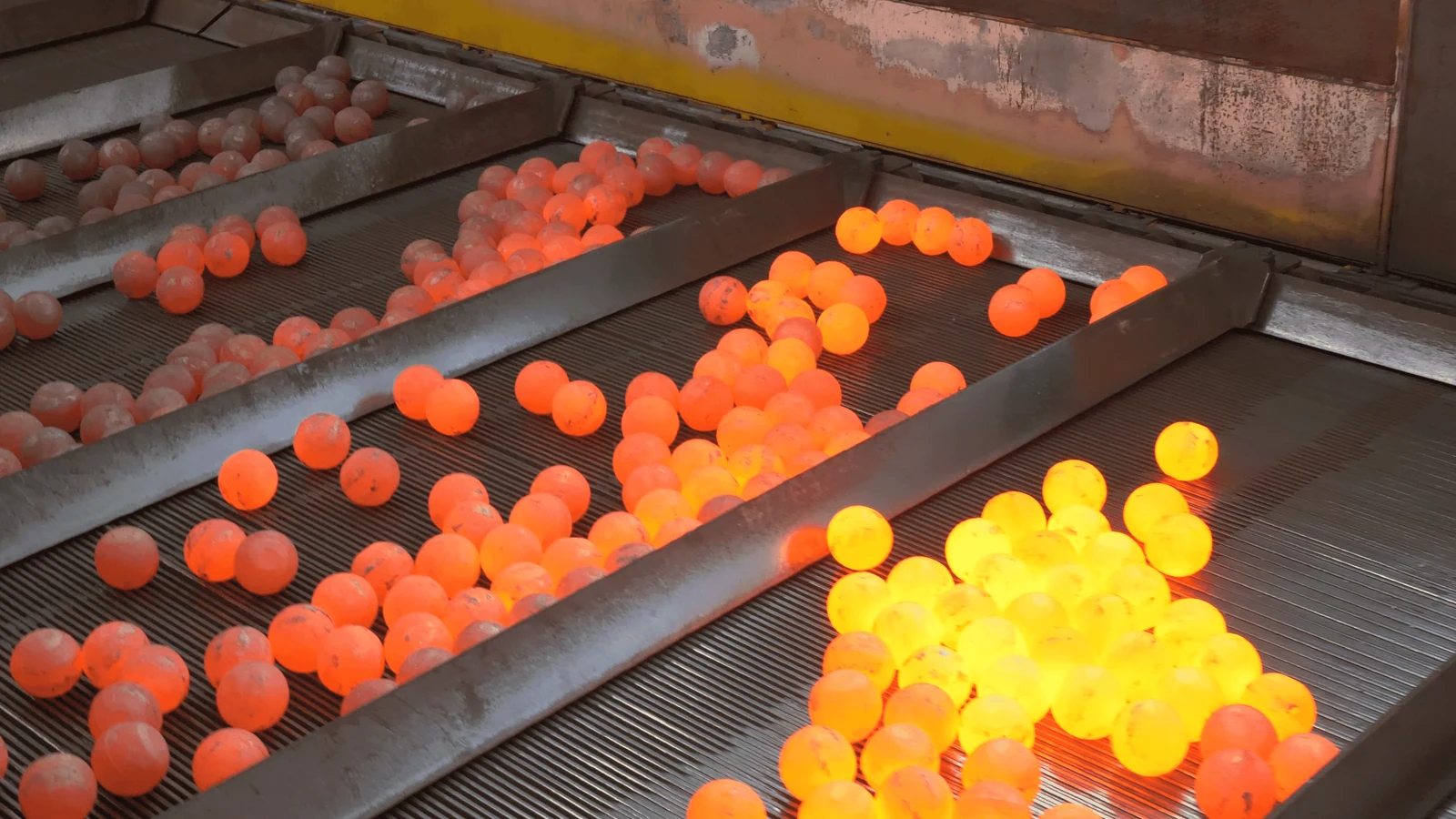
Grinding-ball identification image
06

Grinding Balls

Grinding Balls / Steel Balls

Grinding media subjected to repeated impact and wear. Confirm diameter distribution, ball consumption, mill size, speed, ore hardness, corrosion and breakage rate.

Material Selection: Confirm high-chromium cast balls, forged alloy-steel balls or other media systems validated for the duty according to impact, abrasion, corrosion and target particle size.

View Part Details →
Spare Parts

Bearing Bushes, Ring Gears and Pinion Drive Parts

Check support and drive parts separately against the complete model, shell dimensions, journal, fits, gear parameters, material, heat treatment, lubrication and inspection requirements.

Trunnion bearing bush / bearing liner identification image
01

Trunnion Bearing Bush / Bearing Liner

Trunnion Bearing / Bushing

Supports the mill trunnion and carries radial loads. Confirm journal diameter, bush inside and outside diameters, width, oil grooves, contact pattern, clearance, bearing housing and lubrication.

Material Selection: Confirm bearing bronze, Babbitt metal or the original sliding-bearing material according to bearing pressure, speed, temperature rise, lubrication and repair process.

View Part Details →
Girth gear identification image
02

Girth Gear

Girth Gear / Ring Gear

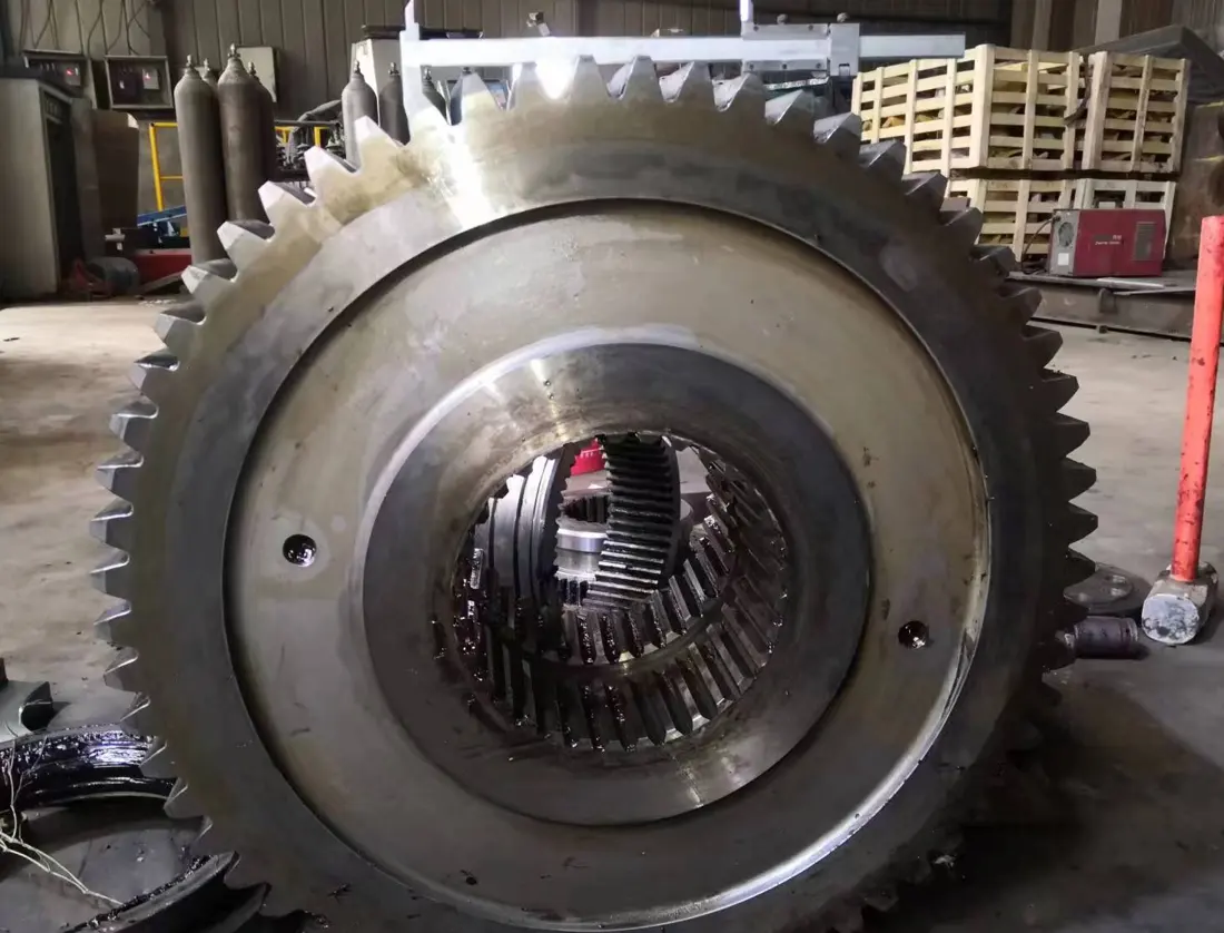
Meshes with the pinion to transmit the main drive. Confirm module, tooth count, pressure angle, helix angle, split joint, center distance, backlash and contact pattern.

Material Selection: Confirm cast steel or forged transmission alloy steel, heat treatment, machining accuracy, NDT and matched-pair inspection against the original design.

View Part Details →
Drive pinion identification image
03

Drive Pinion

Pinion

Meshes with the girth gear to transmit motor and gearbox output. Check module, tooth count, pressure angle, helix direction, shaft interfaces, backlash and contact pattern.

Material Selection: Confirm forged transmission-alloy steel and carburized or quenched-and-tempered heat treatment according to torque, tooth-surface hardness, core toughness and fatigue requirements.

View Part Details →
Drawing and Spare Part Numbers

MQY Drawing Number and Third-Party Part Number Check

MQY part numbers must be confirmed against the complete model, installation position and drawing revision. Numbers are not inferred on this page.

Selection Guidelines: Part numbers must match the model, shell dimensions and installation position. OEM drawing numbers and third-party part numbers are checked separately.

Does an MQY overflow ball mill use discharge grates and pulp lifters?

The overflow discharge arrangement differs from a grate-discharge mill. This page does not treat grates or pulp lifters as standard MQY parts; confirm the installed arrangement from the general arrangement and drawings.

Are liners for different MQY-79 mills directly interchangeable?

No. Mills in the same nominal-diameter series may have different lengths, end configurations, liner arrangements, hole patterns, rotation directions, supports and drives. Confirm the project and drawings.

How can CITIC HIC MQY parts be identified without a drawing number?

Submit the nameplate, shell diameter × length, general arrangement, installation position, used part photographs, liner layout and critical dimensions to assess identification, dimensional survey and manufacturing feasibility.

Submit the CITIC HIC MQY model, shell dimensions, drawing number or liner requirement

Provide the complete model, shell diameter × length, serial number, liner layout, drawings, used part photographs, materials and duty. We coordinate identification, material assessment, manufacturing selection, quality control and finished part delivery.

Manufacturing Services in China

From Technical Assessment to Finished-Part Delivery

ANRANST provides customers worldwide with coordinated consulting, supplier sourcing, quality control and finished-part delivery for custom parts, wear parts and industrial spares from China, with scope to support other custom industrial parts.

01

Technical Advice

Equipment and part identification, drawing review, material selection and manufacturing feasibility assessment.

02

Supplier Introductions

Match requirements with suitable manufacturers in China and coordinate the exchange of technical information.

03

Quality Control

Drawing confirmation, material and process control, production tracking, inspection and acceptance coordination.

04

Finished-Part Delivery

Coordinate manufacturing, quality confirmation, packaging and delivery of complete finished parts.

Provide the existing model, drawings, drawing or part numbers, materials or operating conditions so we can identify the appropriate technical review and supply route.

Submit an Enquiry