>

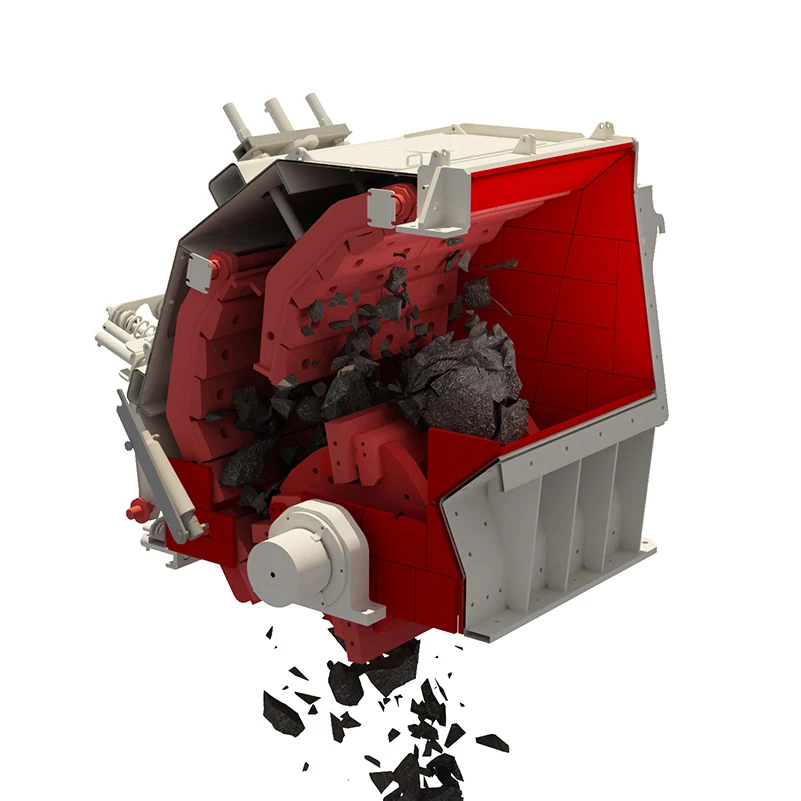
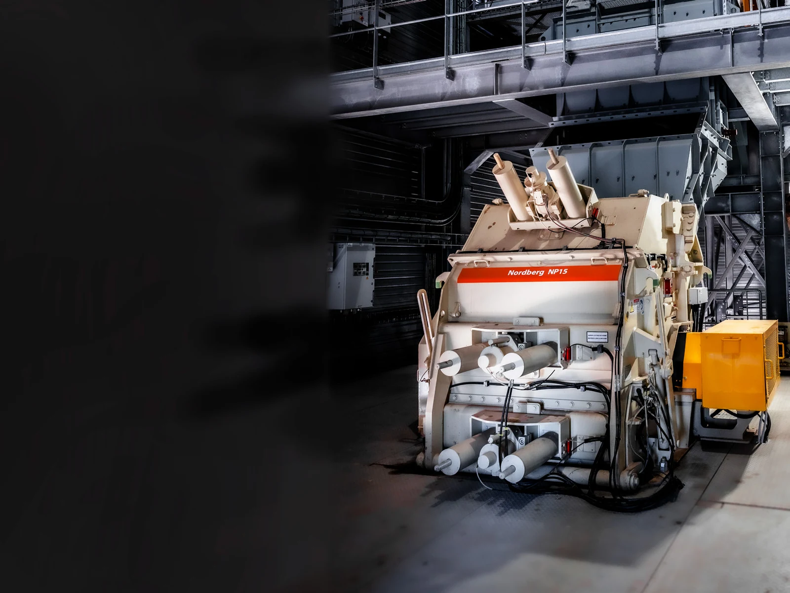
Metso Nordberg NP / NPe Series Impact Crushers

s a Standard Models Entrance Blow Bar, Repulse Liners, Frame Liners, the rotors bearing Hydraulic parts, materials and dedicated maintenance Tool (9)

Metso Nordberg NPe Series HSI Refraining the original factory
Nordberg NPe First and second sections of the original factory data sheet for use Identification The whole machine, the counter-attack and hydraulic areas.
Metso Nordberg NP Series Paragraphs and three counterattacked the original factory
Nordberg NP13, NP15 and NP20 Paragraphs II/III Series Original factory data.
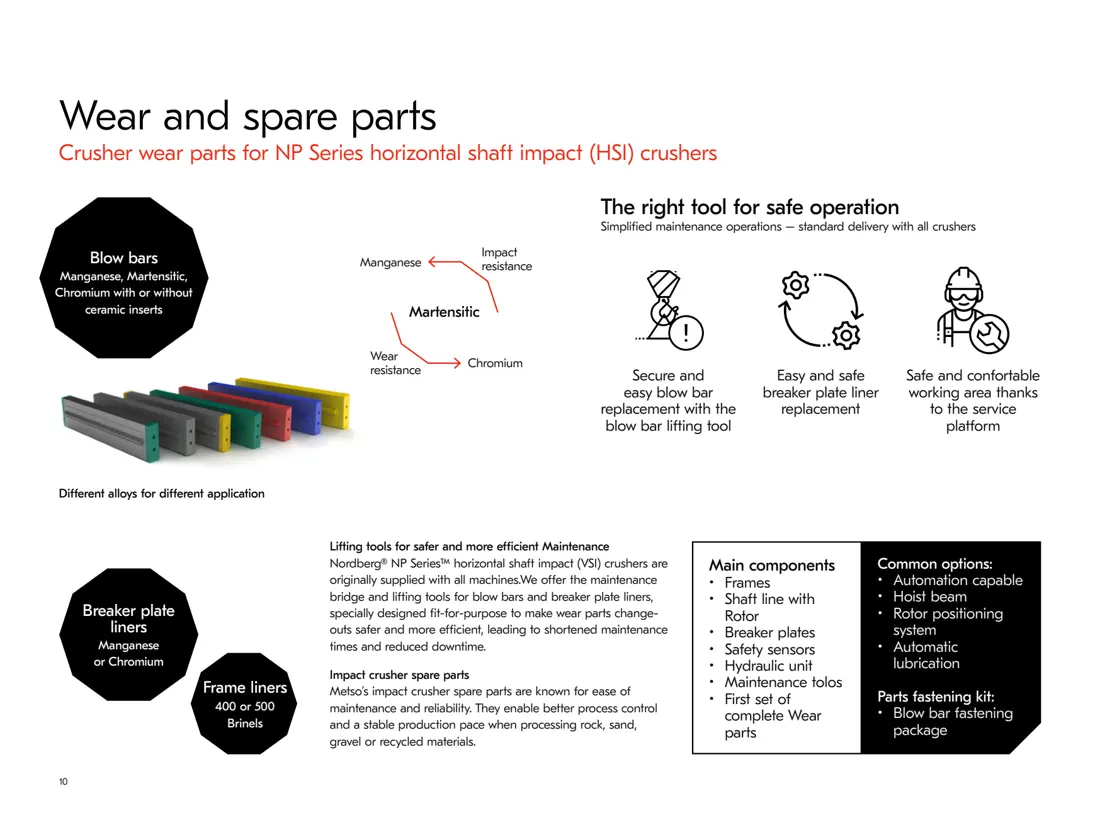
Metso Nordberg NP Series Blow Bar materials, wear parts Maintenance Tool Original Factory Materials
Metso 2025 In the original factory data Blow Bar materials, Repulse Liners, Frame Liners and maintenance Tool Scope.
OEM Equipment Series

model, Wear Parts, Spares and Tooling Completed on a page Identification

This page retains only installed models, core sizes and wear parts/material materials that are directly relevant to the supply of Spare PartS. Manufacturing & Quotation continues with full model; serial number: drawing numbers | The loading machine is reserved for Spare spare part installers (CDP) parts as well AS maintenance tools which will be used in direct connection between Spare'd supplies. Production&quoting continue based on complete Model Nomination Series Number-Drawer Figure(r), Seal Numerous Picture series

9 Original Factory 2025 Information model
3 Category: Application Levels Clustering
6 Key Wear Parts Category
9 Mechanical spare-part categories
Standard Models and Key Dimensions

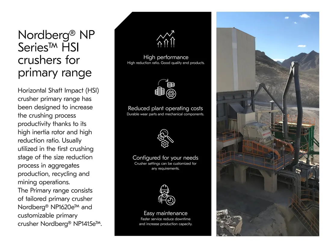
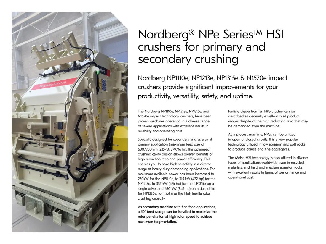
Nordberg NP / NPe Series Model Overview

Feed opening, power and maximum recommended feed sizes Machine Weight for Installation Identification; parts Exchanges still need to be verified serial number Shifter, Transit Configuration and part number.

model / Broken Level Feed opening Maximum recommended feed Power Range Foundations Machine Weight
NP1415 * First Breakdown 1140 × 1540 mm 1000 mm 200–355 kW 22,300 kg
NP1620 * First Breakdown 1430 × 2040 mm 1300 mm 355–630 kW 40,500 kg
NP1110e * First Breakdown/Paragraph II 710 × 1020 mm 600 mm 110–250 kW 9,300 kg
NP1213e * First Breakdown/Paragraph II 750 × 1320 mm 600 mm 200–315 kW 13,000 kg
NP1315e * First Breakdown/Paragraph II 805 × 1540 mm 600 mm 250–355 kW 16,200 kg
NP1520e * First Breakdown/Paragraph II 850 × 2040 mm 700 mm 355–630 kW 27,500 kg
NP13 * Paragraphs II/III 560 × 1320 mm 350 mm 200–315 kW 11,900 kg
NP15 * Paragraphs II/III 595 × 1540 mm 400 mm 250–355 kW 15,700 kg
NP20 * Paragraphs II/III 700 × 2040 mm 500 mm 355–630 kW 26,000 kg
Check-in: NP1213e / NP13 / NP1315e / NP15 / NP1520e / NP20 — / / / / / — NPe/Np-, NP and the P. The original data on rotor diameters are shared with platehammer weight levels respectively but cannot be directly determined by part interchange; it is necessary to continue checking of rotary slot (transponder), sheet metal profile(r) or sealing system as well a serial number in addition for parts numbers. (;;;;; ) View Metso 2025 Original Factory model information
Wear Parts

Tracks in the impact location and Material System Identification NP wear parts

The impact, sliding and grinding of the hammers on boarding plates with counter-shockers are different from those in rack. Materials link explains performance boundaries to operating conditions; common parts pages carry a unified RFQ system

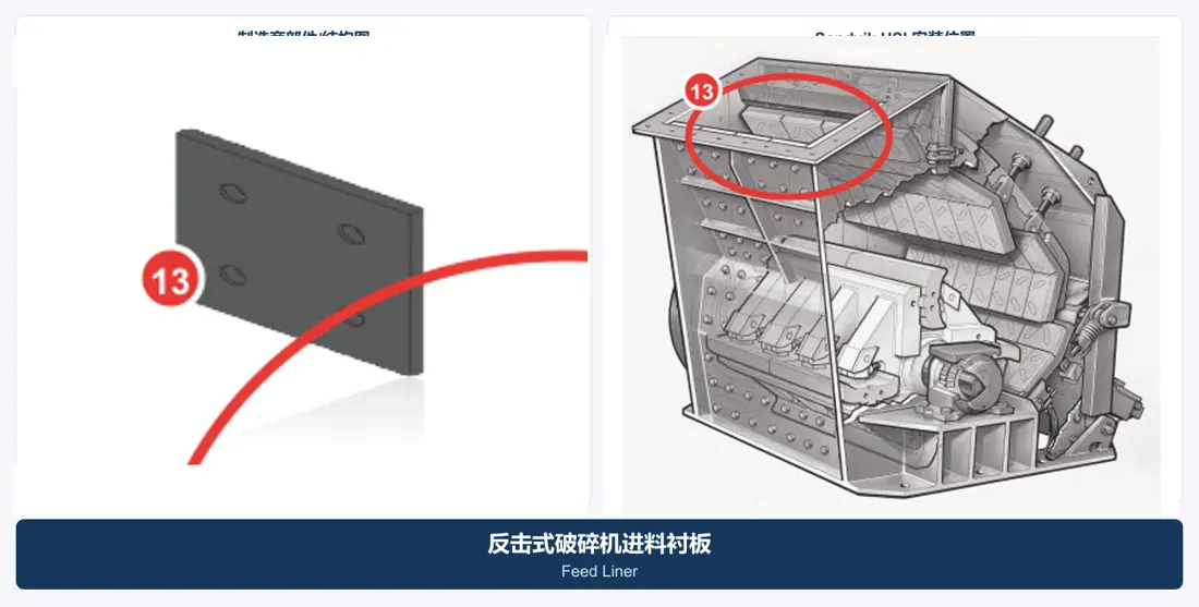
Primary Apron Liner General Part type Figures
02

Primary Apron Liner

First Apron Liner

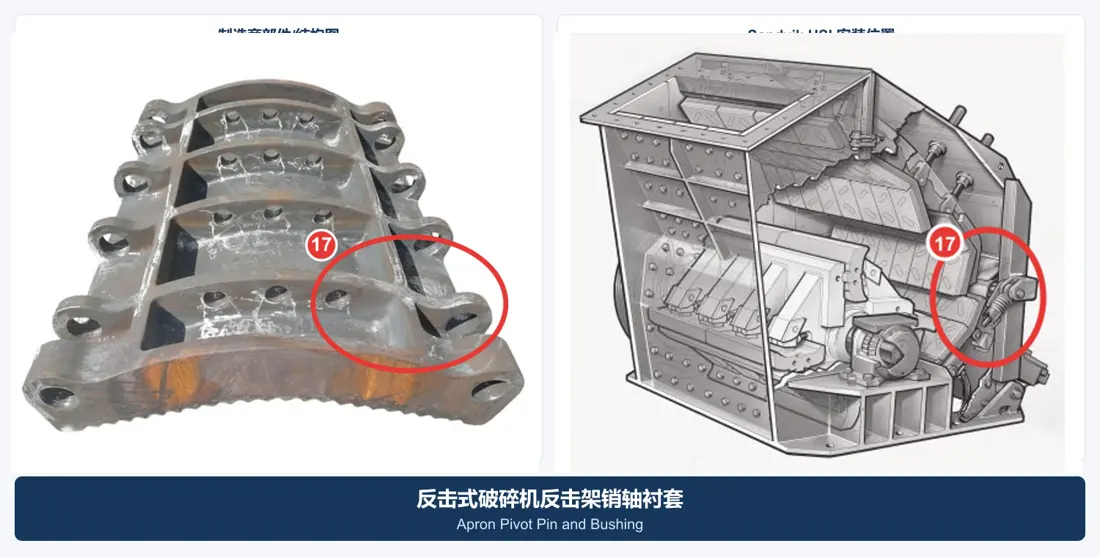
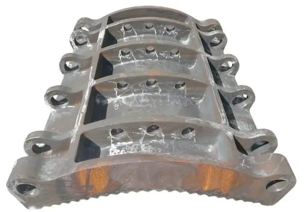
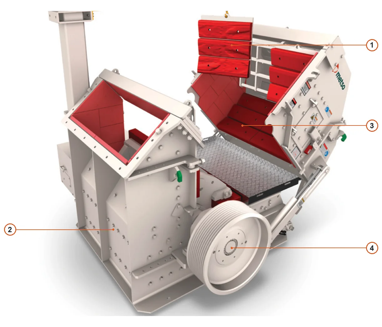
The first impact and abrasive wear after the plate hammer is thrown. Metso' public scope for high-manganese steel or highlychrome materials, depending on feed shocking as well in terms of corrosionability. Image used to identify parts categories; finally confirmed by full model (NP), serial number(r) partdrawal numbers/contourage figures with profile sizes).

View General Part Details →
Secondary Apron Liner General Part type Figures
03

Secondary Apron Liner

Second Apron Liner

The following fracture and rectification zones are subject to repeated shocks, sliding wear as well in terms of grain control; materials cannot be determined separately from the actual operating conditions. Image is used for identifying parts categories: finally confirmed by a full model with an NNP series number (part-drawing numbers), profile size or interface dimensions

View General Part Details →
Frames of the aircraft side liners General Part type Figures
04

Frames of the aircraft side liners

Frame / Side Liner

The interior walls of the frame are protected from particle scrubbing and rebound wear.The original factory' public scope includes plate-based abrasion materials at about four hundred or fifty Brinell levels, which is used to identify parts categories; finally confirmed by NFP complete model with serial number as partdrawing numbers in outline sizes for interface dimensions (400; 500)

View General Part Details →
Rotor Protective Liner General Part type Figures
05

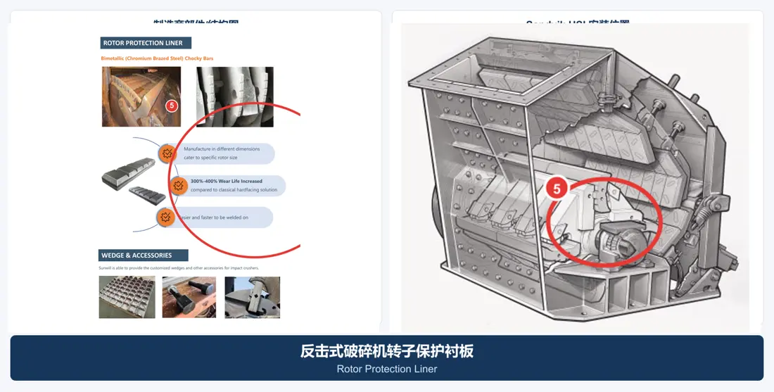
Rotor Protective Liner

Rotor Protection Liner

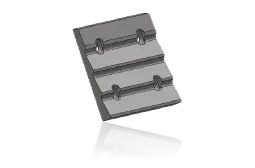
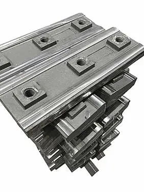
Protection of the impact-prone and grinding areas in rotors; installation surfaces, weighting requirements must be consistent with a rotating configuration. Image for identifying parts categories: finally confirmed by NNP complete model (serial number), partdrawal numbers as well AS profiles or interface dimensions

View General Part Details →
Spare Parts

rotors, sleevers and hydraulic Fastening system

The common spare parts are confirmed by loading, fits and lubrication as well in the interface dimensions. Card entries into a unified part page where OEM install information continues to complete modeling with serial number check-ups on this pages

Rotor Assemblies General Part type Figures
01

Rotor Assemblies

Rotor Assembly

The rotor, axis and plated load core; the diameter of a rotary to be determined by contrasting its widths with their configuration as well for balancing grade levels. Image is used in identifying parts categories which are ultimately confirmed according TO THE full model (NP), serial number(S) or partial drawing numbers/contour sizes).

View General Part Details →
Rotor Main Shaft General Part type Figures
02

Rotor Main Shaft

Rotor Shaft

The punching and shock loads are required to be confirmed by forging, heat treatment (heat processing), shaft neckline(axis) or round corner/NDT-and dynamic balance requirements. Image is used in identifying parts categories; finally confirm the full model of a NNP series number as partdrawal numbers with profile size on interface dimensions

View General Part Details →
Rotor Bearing General Part type Figures
03

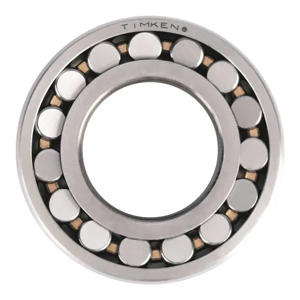
Rotor Bearing

Rotor Bearing

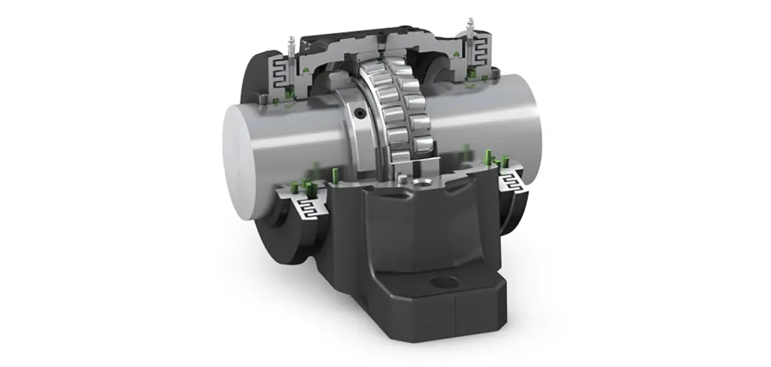
The high-speed heavy load rotor is selected depending on the loading, speeding and grooves; it can be used to identify parts categories. It will eventually confirm by a full model of NNP (serial number), partial drawing numbers or profile as well in interface dimensions).

View General Part Details →
bearing housing General Part type Figures
04

Bearing Housing

Bearing Housing

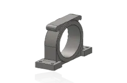
The bearing positioning, load delivery and sealant structures must be matched with the pore system / center heights of a pair. Image is used to identify parts categories; finally confirmed by NNP complete model (serial number), part-drawn numbers as well in outline or interface dimensions

View General Part Details →
Apron Adjustment Cylinder General Part type Figures
06

Apron Adjustment Cylinder

Apron Adjustment Cylinder

For counter-helicopter position adjustment with overload release action; check the cylinder diameter, itinerary and installation of ear shafts. The image is used to identify parts categories: finally confirmed by a full model (NP), serial number(r) or partial drawing numbers/contouring figures as well in interface dimensions).

View General Part Details →
Impact Apron Assembly General Part type Figures
08

Impact Apron Assembly

Impact Apron Assembly

The package includes a load frame, liner mounting surface and adjustment as well AS/S; the supply requires matching of models with rack configurations to be configured on site. Image for identifying parts categories: finally confirmed by NNP complete model (number), serial number(r) or partial drawing numbers in terms outline size).

View General Part Details →
Blow Bar Fastening system General Part type Figures
09

Blow Bar Fastening system

Blow Bar Fastening System

The weight, contact surface and locking structures must be consistent with the plate hammers or rotor slot. Image is used to identify parts categories; finally confirmed by a full model of NNP (serial number), part-drawn numbers) profile as well in interface dimensions

View General Part Details →
Specialized Tooling

NP Series Original factory maintenance Tool Security Operations System

Metso 2025 Clearly listed information Blow Bar sling Tool, Repulse Liners Replacement of support and repair platforms; Tool The scope of application remains specific NP / NPe model and serial number Confirmation.

NP SERIESMetso NP Series Blow Bar sling Tool Original Factory Materials

Blow Bar sling Tool

for Blow Bar Demolition and controlled suspension, reducing the risk of manual handling. RFQ Needs to be provided model, Blow Bar Contours, single-piece weight and field lifting conditions.

NP SERIESMetso NP Series Breaker Plates Liners Replacement of regional original plant data

Repulse Liners Replacement Support

NP13, NP15 and NP20 Removables of Disposible Breaker Plates Boxes Construction Used for completion outside Liners Replacement.Specific ceilings, weight and operating space Installation-specific Confirmation.

NP SERIESMetso NP Series Refining the original factory data

Repairing bridges, rotor position and operating platforms

For the entry of a rotor, Blow Bar, Repulse Liners and high-end Frame Liners Regions. Tool Packages must be with Model, backstage Construction, field space and security interlock matching.

RFQ NP Series Blow Bar What information do you need?

Please provide complete model, serial number, Blow Bar Node or drawing number, Current Material, single-piece weight and rotor Configuration, feed grain size and material abrasiveness as well with worn-out old items.

Nearby model Can we directly share? Blow Bar ?

Cannot. Even if the rotor diameter and plate hammer weight are identical in public information, it is necessary to continue checking of a rotary slots (transit) with an outline for plates or board marks; tightening systems: serial number & part numbers

Blow Bar materials How to choose?

high-manganese steel, Martensitic Steel, high-chromium cast iron and ceramic / MMC Strengthening boundaries based on maximum feed, impact and abrasion risk. failure modes Choices.

Submission NP / NPe model, Blow Bar Node or spare parts Drawings

Provide complete model, serial number / nameplates and partial drawing numbers; photos of used parts (key sizes), available materials & operating conditions. We are able to perform part recognition as well in the process for parts assessment purposes: manufacturing organization quality control with finished-part delivery

Manufacturing Services in China

From Technical Assessment to Finished-Part Delivery

ANRANST provides customers worldwide with coordinated consulting, supplier sourcing, quality control and finished-part delivery for custom parts, wear parts and industrial spares from China, with scope to support other custom industrial parts.

01

Technical Advice

Equipment and part identification, drawing review, material selection and manufacturing feasibility assessment.

02

Supplier Introductions

Match requirements with suitable manufacturers in China and coordinate the exchange of technical information.

03

Quality Control

Drawing confirmation, material and process control, production tracking, inspection and acceptance coordination.

04

Finished-Part Delivery

Coordinate manufacturing, quality confirmation, packaging and delivery of complete finished parts.

Provide the existing model, drawings, drawing or part numbers, materials or operating conditions so we can identify the appropriate technical review and supply route.

Submit an Enquiry