
01
Concave Liners
Concaves
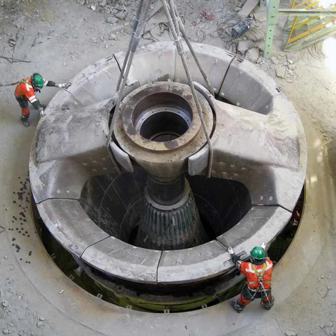
Installed inside upper and lower shells under ore impact, compression and sliding. Confirm chamber profile, segmentation and retention by full model.
Start with model and machine layout to identify concaves, mantles, spiders, main shafts, protective sleeves, spider bushings, eccentrics and drive spares. Drawings guide manufacturing in China, quality control and delivery.
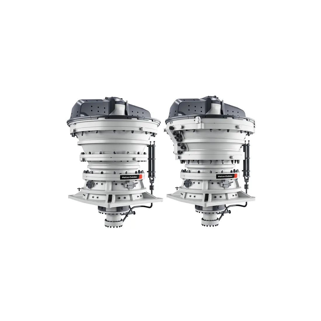
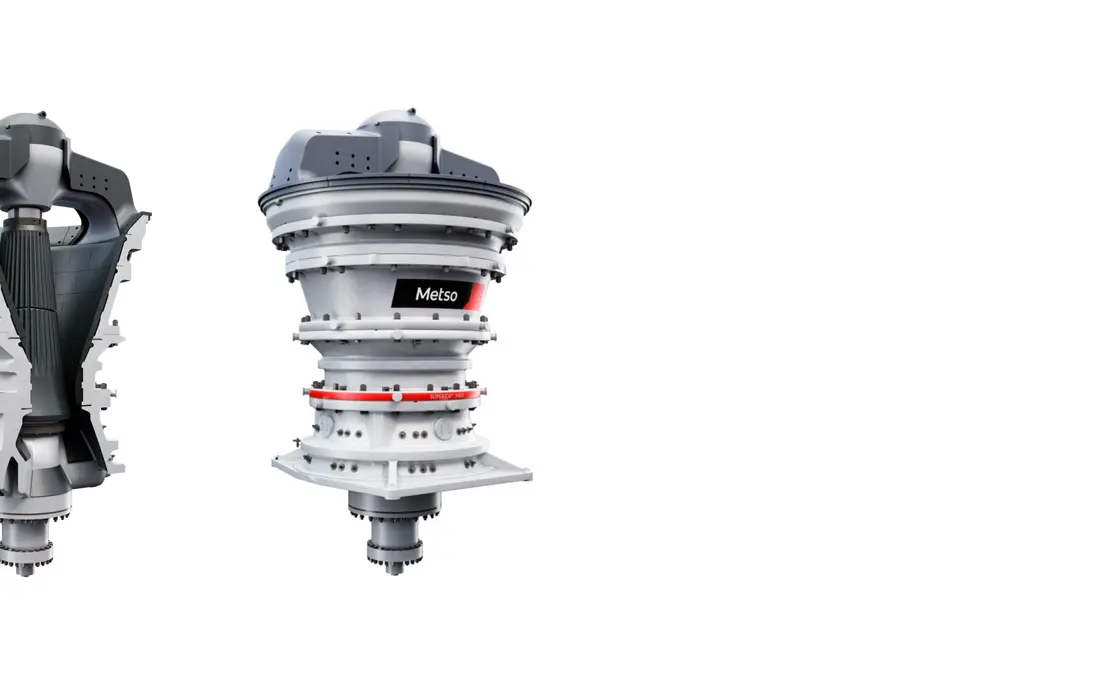
Superior™ MKIII is Metso's current primary gyratory range. ANRANST focuses on chamber wear parts, spider and main-shaft systems, copper-alloy sliding pairs, eccentric and gear drives, hydraulic supports and service interfaces. Full installed-machine identification remains essential.
The table screens installed models and spare scope. Capacities are Metso's published maxima for a typical feed curve, material density of 2.75 t/m³ and maximum eccentric throw.
| Model | Key Dimensions and Capacity | Identification Context |
|---|---|---|
| Superior™ MKIII 42-65 | Weight 120 t; opening 1,066 mm; power 450 kW; maximum capacity 5,250 t/h | Compact standard model |
| Superior™ MKIII 50-65 | Weight 153 t; opening 1,270 mm; power 450 kW; maximum capacity 6,375 t/h | Large feed, compact footprint |
| Superior™ MKIII 54-75 | Weight 242 t; opening 1,370 mm; power 600 kW; maximum capacity 7,500 t/h | Medium-scale hard-rock duty |
| Superior™ MKIII 62-75 | Weight 298 t; opening 1,575 mm; power 600 kW; maximum capacity 8,750 t/h | Standard model with large opening |
| Superior™ MKIII 60-89 | Weight 365 t; opening 1,525 mm; power 750 kW; maximum capacity 12,500 t/h | High-throughput standard model |
| Superior™ MKIII 70-89 | Weight 430 t; opening 1,780 mm; power 900 kW; maximum capacity 15,000 t/h | Largest opening in the range |
| Superior™ MKIII 60-110 | Weight 553 t; opening 1,525 mm; power 1,500 kW; maximum capacity 17,000 t/h | High-power, high-capacity model |
| Superior™ MKIII 6275UG | Weight 280 t; maximum feed 1,440 mm; approximately 5,700 × 5,600 × 4,650 mm | Compact Underground and Surface Configuration |
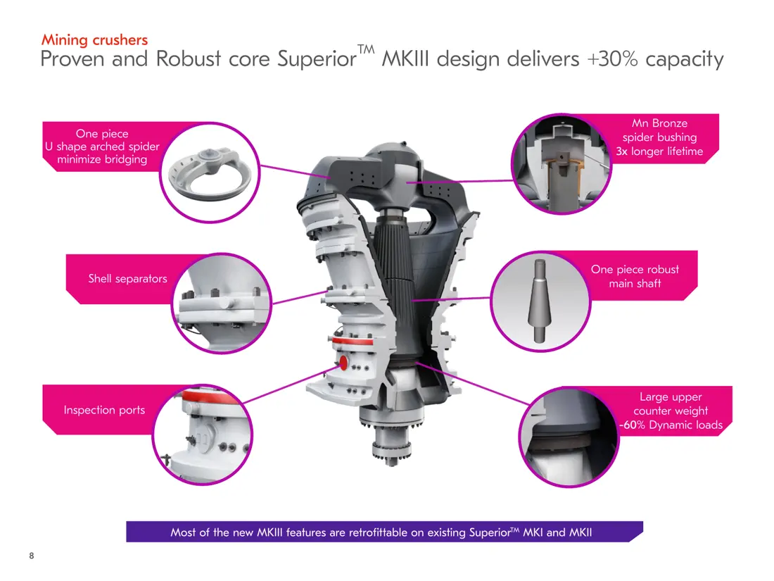
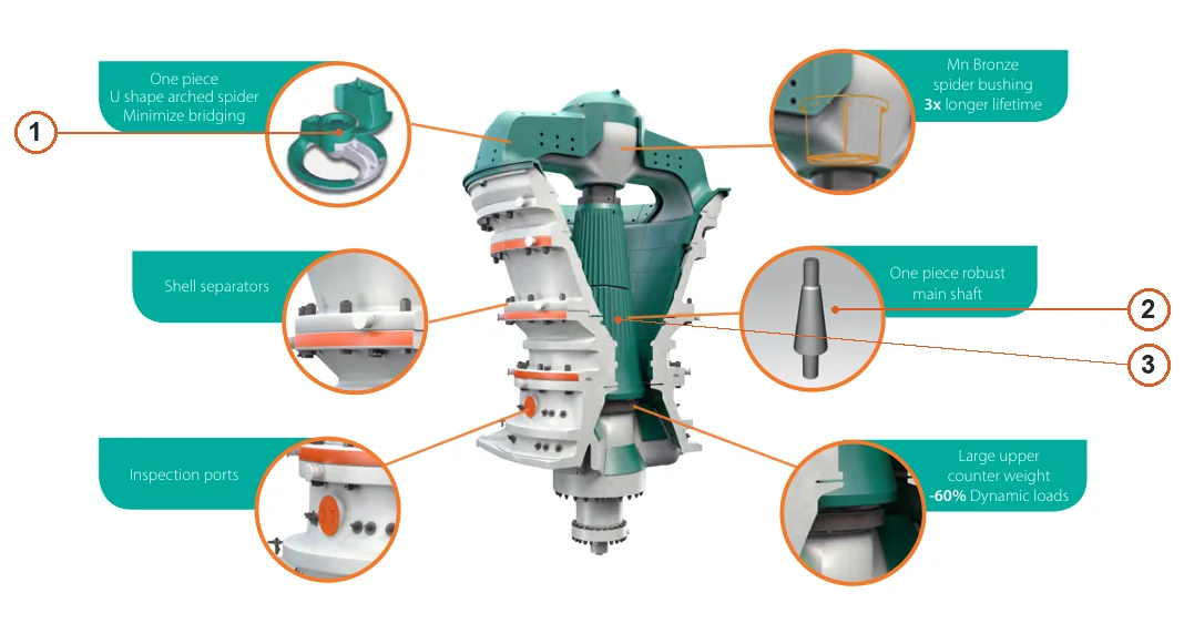
The numbers on the diagram correspond one to one with the rows below.
| No. | Component | Location | Applies to |
|---|---|---|---|
| 1 | Spider | Spider component in upper-left detail | Superior MKIII series |
| 2 | Main shaft | Detached main shaft in middle-right detail | Superior MKIII series |
| 3 | Mantle | Conical crushing mantle around shaft in central cutaway | Superior MKIII series |
Identify impact, compression and sliding abrasion by position before selecting material, heat treatment, chamber profile, segments and fasteners.
Concaves
Installed inside upper and lower shells under ore impact, compression and sliding. Confirm chamber profile, segmentation and retention by full model.
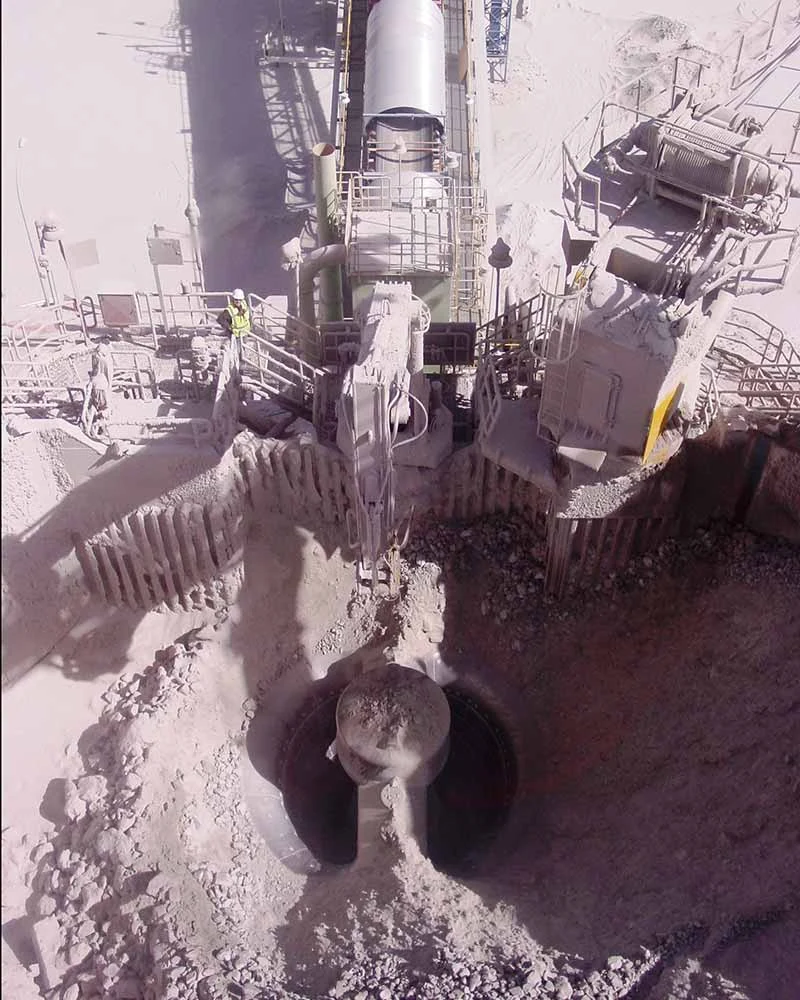
Mantle
Cover the head and form the chamber with concaves. Select material and profile by chamber, closed-side setting, material and wear distribution. Image shows installation position.
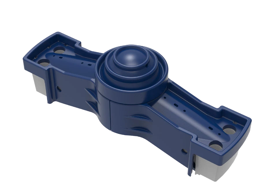
Spider Arm Shields
Protect spider arms and upper feed areas from direct large-rock impact. Prioritize toughness, fit and reliable fastening. Image identifies the category.
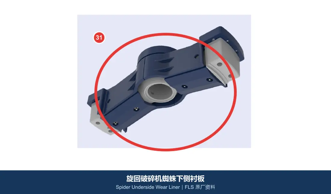
Spider Underside Wear Liners
Under the spider and above the chamber, these resist rebound and erosion. Distinguish impact from sliding zones by position. Image identifies the category.
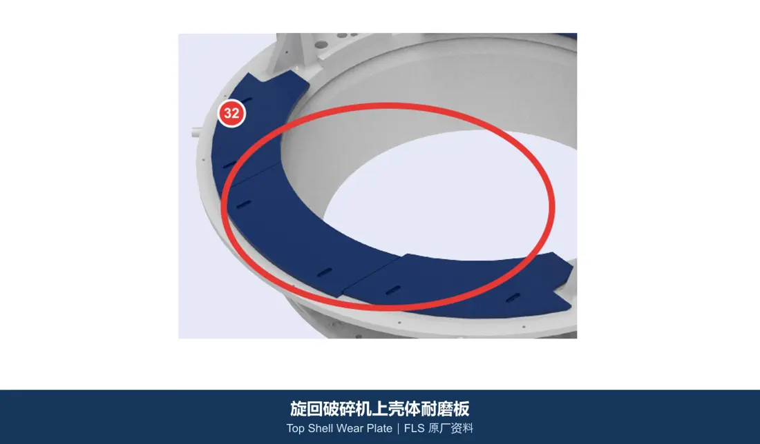
Top Shell Wear Plates
Protect upper-shell internal and secondary surfaces. Select cast wear parts, quenched-and-tempered plate or composites by impact/abrasion balance. Image identifies the category.
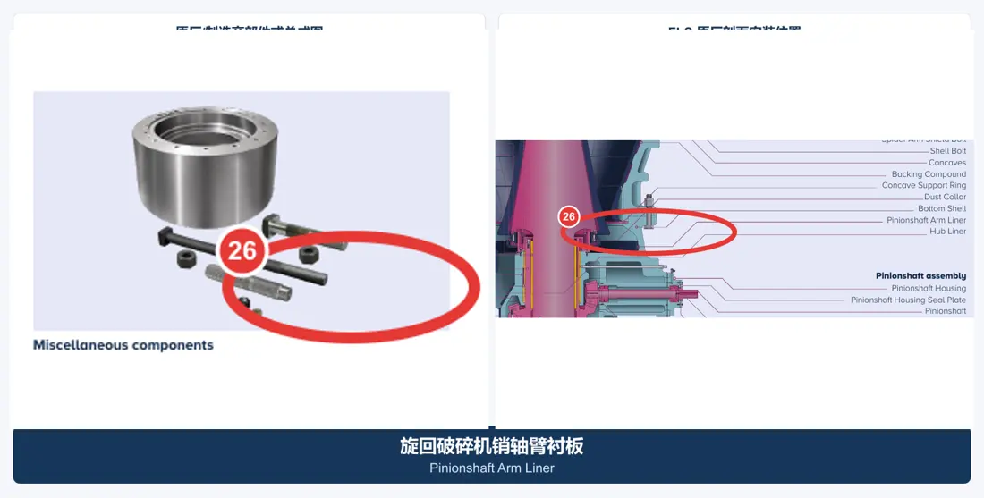
Pinionshaft Arm Liners
Protect the shell around the drive-shaft arm from falling-feed impact and fines abrasion. Check holes, profile, thickness and replacement space. Image identifies the category.
Identify spider, main shaft, protective sleeve and spider bushing separately. Check eccentric, gears, bearings and hydraulics together with adjacent assemblies.
Spider / Spider Assembly
Spans the feed opening and guides the shaft's upper end. Distinguish spider body, cap, guards, bushing, seals and connections in the enquiry.
View the General Component Page →Main Shaft
A separate forged-steel load-bearing part supporting the head and transmitting gyratory loads. Check journals, tapers, threads, material, heat treatment and nondestructive testing.
View the General Component Page →
Mainshaft Protective Sleeve
A separate protective part around the shaft, distinct from the shaft itself and quoted separately from the assembly. Check fitting sections, interference and surface requirements.
View the General Component Page →Spider Bushing
At the spider centre, it guides the shaft's upper end. Official construction literature identifies a manganese-bronze bushing for MKIII. Check material, clearance, oil grooves and concentricity together.
View the General Component Page →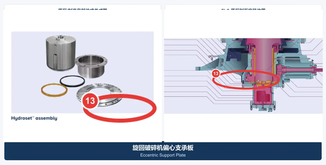
Eccentric Assembly & Bushings
Drive shaft and head gyration. Include eccentric body, bushing, gear, thrust wear parts and adjacent lubrication interfaces. Image identifies the category.
View the General Component Page →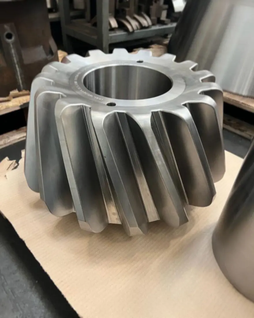
Gear & Pinion Set
Transmit torque to the eccentric. Treat the gear pair as a matched system; check tooth system, material, heat treatment, contact and backlash. Image identifies the category.
View the General Component Page →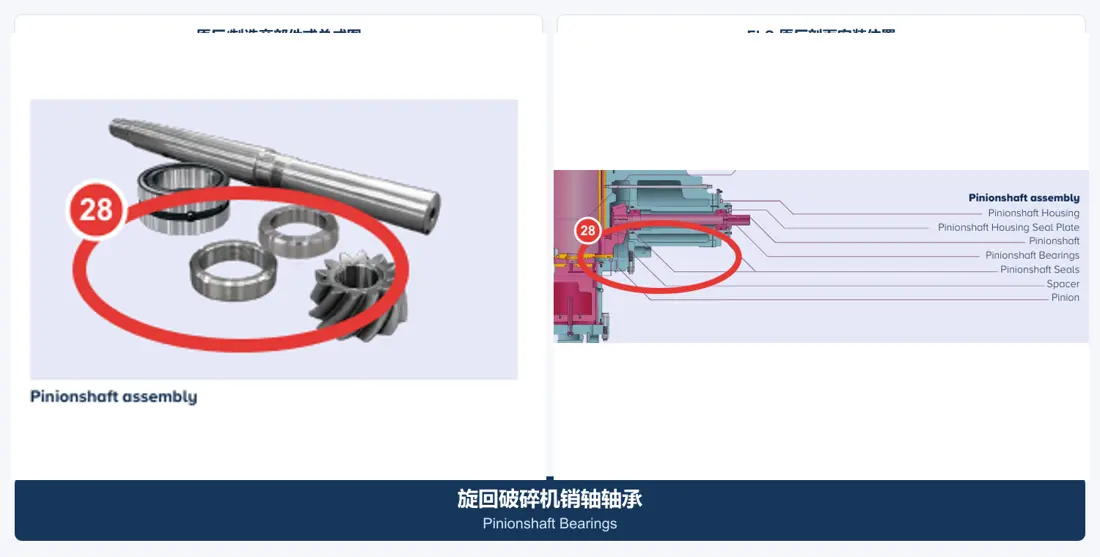
Pinionshaft & Bearings
Include shaft, bearings, housings and seals. Check the assembly against gear pairing, centre distance, lubrication and bearing clearance. Image identifies the category.
View the General Component Page →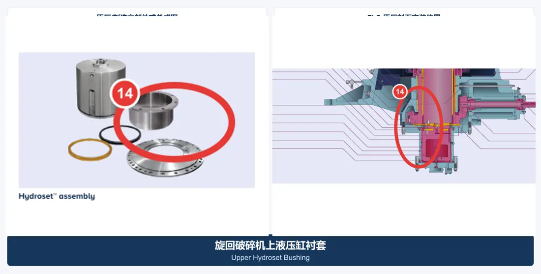
Hydroset Bushings & Seals
Include upper/lower cylinder bushings, piston seals and adjustment interfaces. Check pressure, temperature, hydraulic oil, clearance and seal section. Image identifies the category.
View the General Component Page →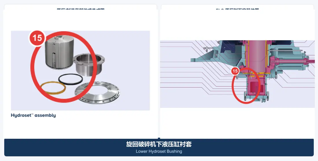
Bottom Shell Bushing
In the lower-shell support and sliding area. Confirm copper-alloy grade, centrifugal casting quality, bore, cylindricity, oil grooves and running clearance together. Image identifies the category.
View the General Component Page →Only maintenance structures confirmed in Metso literature are shown. Tool supply or customization requires assessment of configuration, weight, lifting points and service space.
Metso confirms hydraulic shell separation and independent shell lifting for MKIII. Verify the site method against actual interfaces, lifting points, weight and service space.
Official diagrams show shell separators and inspection ports, providing a starting reference for tooling interfaces, disassembly sequence and safety planning.
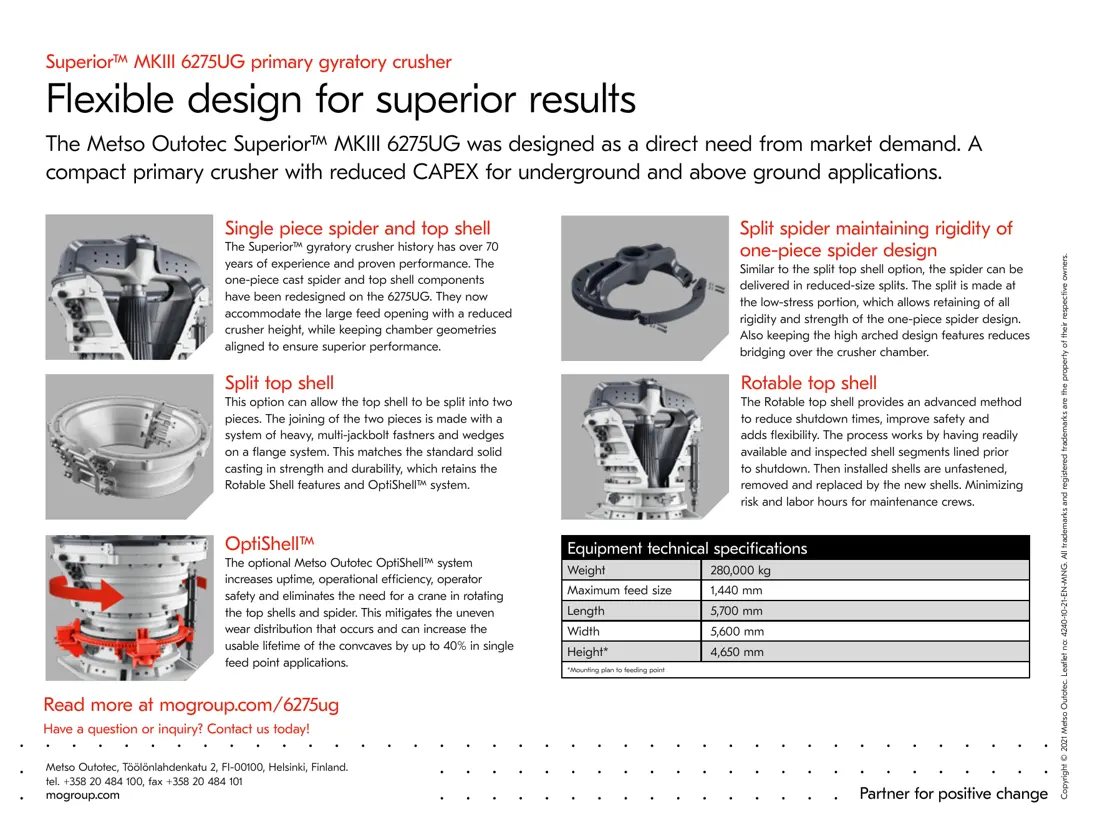
6275UG literature lists optional OptiShell™ for rotating the upper shell and spider. Confirm applicability to an existing machine by configuration and official interfaces.
Full model, serial number, assembly/part reference, latest drawing, current-part photographs, material, key dimensions, processed material and failure details.
No. The shaft is the internal load-bearing forging; the sleeve is a separate outer protection part. Identify, measure and quote them separately.
The model only narrows the scope. Liners need chamber verification; gears and bushings also require drawing, tooth system, fits, material, serial number and revision.
Browse component descriptions, drawing requirements and enquiry details.
Provide nameplate, serial number, photographs, drawings, material and duty for identification, material assessment, production at certified foundries, quality control and delivery.
Or contact us directly: +86 156 3797 3199
zzx@anranst.com
ANRANST provides customers worldwide with engineering assessment, production at certified foundries to the customer technical requirements, quality control and finished-part delivery for custom wear parts and industrial spares, with scope to support other custom industrial parts.
We review mating surfaces and interface dimensions and assess material, heat treatment and manufacturing feasibility.
Material grades and heat-treatment processes are specified order by order, stated in the technical agreement and tracked through production.
Drawing confirmation, material and process control, production tracking, inspection and acceptance coordination.
We coordinate manufacturing, quality confirmation, packaging and delivery of complete finished parts in a workable, closed-loop supply process.
Provide the equipment brand, complete model and serial number, part name, part number or drawing number, drawing revision, quantity, material requirements and duty. If identifiers are unavailable, send photographs and key dimensions.
Submit an Enquiry