
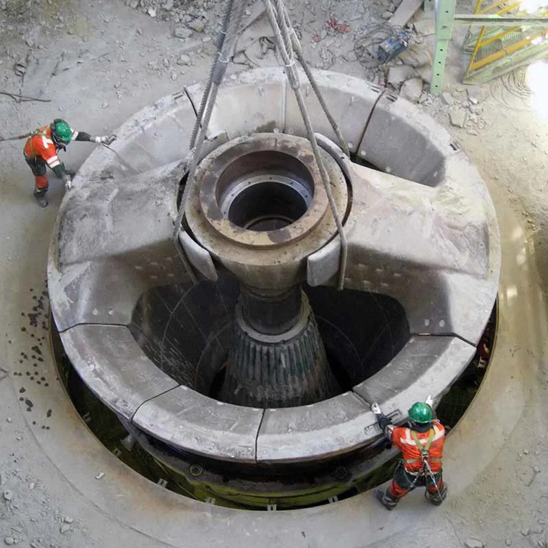
01
بطانات الغطاء الثابت (كونكيف)
Concaves
تركب داخل الأغلفة العلوية والسفلية تحت صدمات الخام وضغطه وانزلاقه. طابق شكل الحجرة والتقسيم إلى أجزاء والتثبيت حسب الطراز الكامل.
ابدأ بطراز الآلة وترتيبها لتحديد الأغطية الثابتة (كونكيف) والمانتلات (المخاريط المتحركة) والعارضات العلوية والأعمدة الرئيسية والجلب الواقية وجلب العارضات العلوية واللامراكز وقطع غيار نظام الإدارة. توجه الرسومات التصنيع في الصين ومراقبة الجودة والتسليم.
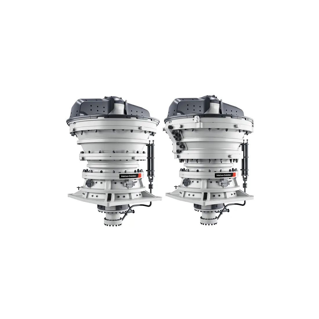
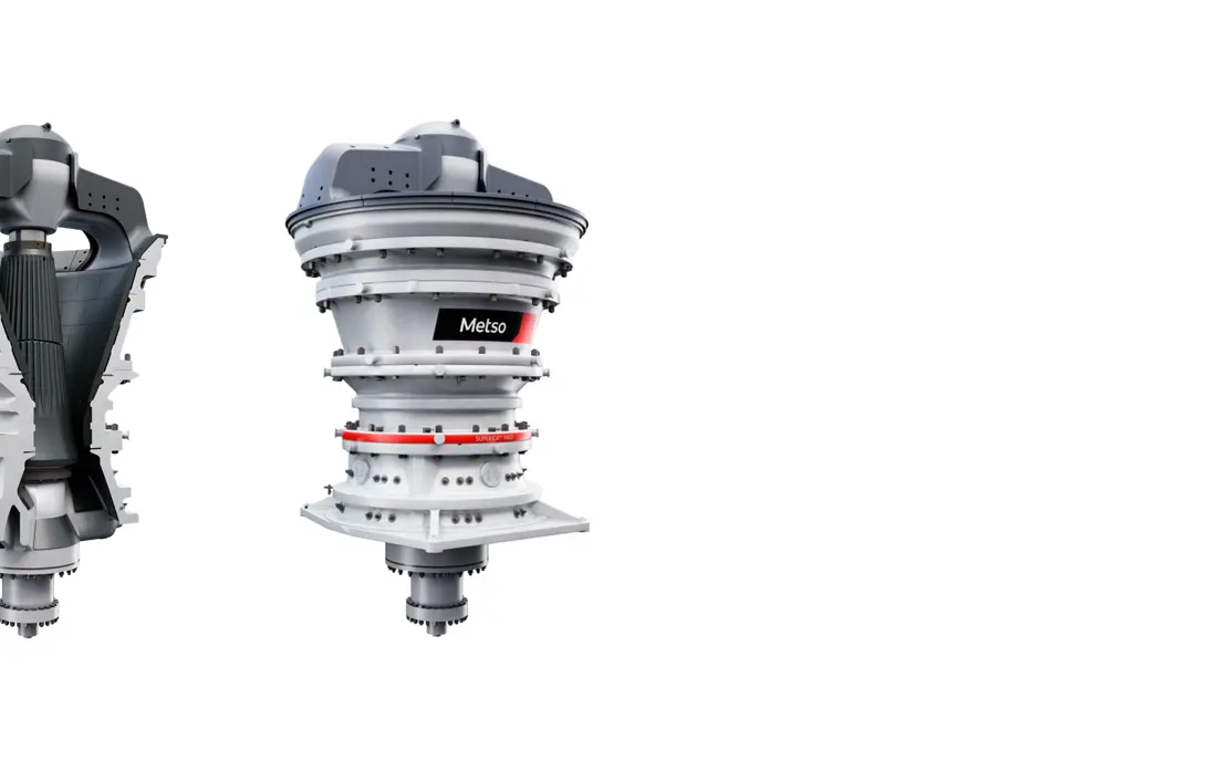
Superior™ MKIII هي المجموعة الحالية من الكسارات الدوارة الأولية من Metso. تركز ANRANST على قطع تآكل الحجرة وأنظمة العارضة العلوية والعمود الرئيسي وأزواج الانزلاق من سبائك النحاس وأنظمة الإدارة اللامركزية وبالتروس والدعامات الهيدروليكية وواجهات الصيانة. يبقى التحديد الكامل للآلة المركبة ضروريا.
يساعد الجدول على فرز الطرازات المركبة ونطاق قطع الغيار. الإنتاجيات هي القيم القصوى المنشورة من Metso لمنحنى تغذية نموذجي وكثافة مادة 2.75 t/m³ وأقصى شوط لامركزي.
| Model | الأبعاد الرئيسية والإنتاجية | سياق التحديد |
|---|---|---|
| Superior™ MKIII 42-65 | الوزن 120 t؛ الفتحة 1,066 mm؛ القدرة 450 kW؛ أقصى إنتاجية 5,250 t/h | طراز قياسي مدمج |
| Superior™ MKIII 50-65 | الوزن 153 t؛ الفتحة 1,270 mm؛ القدرة 450 kW؛ أقصى إنتاجية 6,375 t/h | تغذية كبيرة ومساحة تركيب مدمجة |
| Superior™ MKIII 54-75 | الوزن 242 t؛ الفتحة 1,370 mm؛ القدرة 600 kW؛ أقصى إنتاجية 7,500 t/h | تشغيل متوسط النطاق للصخور الصلبة |
| Superior™ MKIII 62-75 | الوزن 298 t؛ الفتحة 1,575 mm؛ القدرة 600 kW؛ أقصى إنتاجية 8,750 t/h | طراز قياسي بفتحة كبيرة |
| Superior™ MKIII 60-89 | الوزن 365 t؛ الفتحة 1,525 mm؛ القدرة 750 kW؛ أقصى إنتاجية 12,500 t/h | طراز قياسي عالي الإنتاجية |
| Superior™ MKIII 70-89 | الوزن 430 t؛ الفتحة 1,780 mm؛ القدرة 900 kW؛ أقصى إنتاجية 15,000 t/h | أكبر فتحة في المجموعة |
| Superior™ MKIII 60-110 | الوزن 553 t؛ الفتحة 1,525 mm؛ القدرة 1,500 kW؛ أقصى إنتاجية 17,000 t/h | طراز عالي القدرة والإنتاجية |
| Superior™ MKIII 6275UG | الوزن 280 t؛ أقصى حجم تغذية 1,440 mm؛ حوالي 5,700 × 5,600 × 4,650 mm | تكوين مدمج للاستخدام تحت الأرض وعلى السطح |
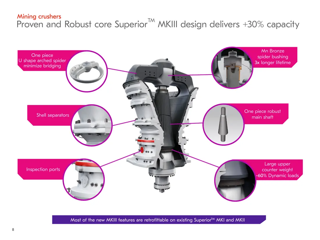
تتطابق الأرقام على المخطط مع الصفوف أدناه.
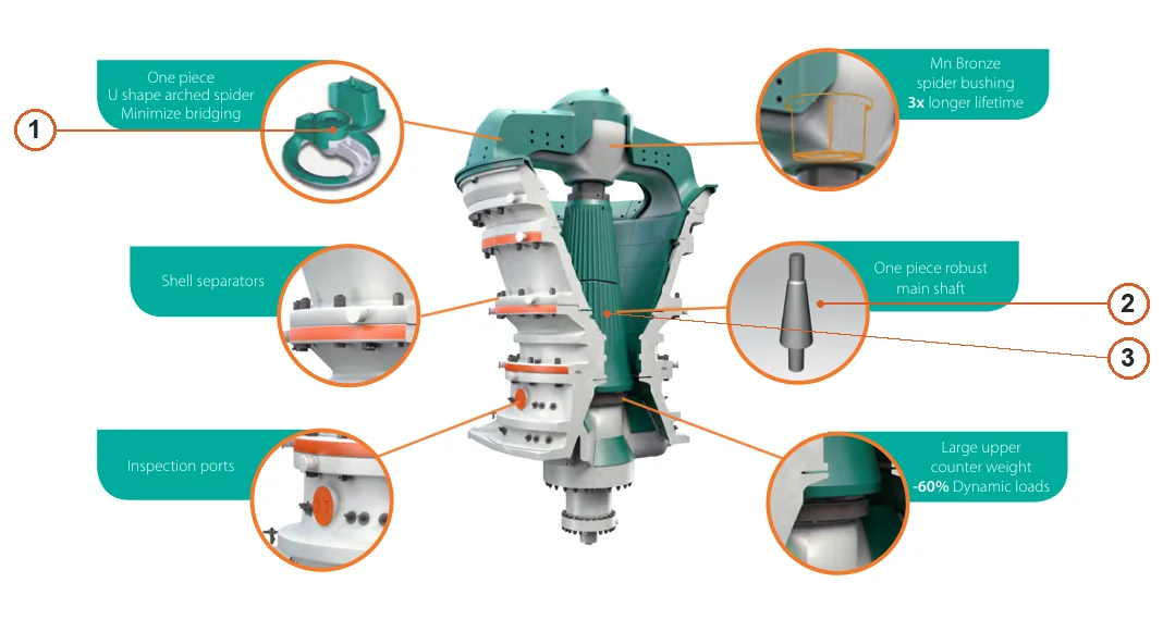
| الرقم | المكوّن | الموضع | ينطبق على |
|---|---|---|---|
| 1 | Spider | جزء العارضة العلوية في التفصيل العلوي الأيسر | سلسلة Superior MKIII |
| 2 | العمود الرئيسي | عمود رئيسي معروض منفصلا في التفصيل الأوسط الأيمن | سلسلة Superior MKIII |
| 3 | Mantle | المانتل المخروطي حول العمود في المقطع المركزي | سلسلة Superior MKIII |
حدد الصدم والضغط والسحج الانزلاقي حسب الموضع قبل اختيار المادة والمعالجة الحرارية وشكل الحجرة والأجزاء والمثبتات.
Concaves
تركب داخل الأغلفة العلوية والسفلية تحت صدمات الخام وضغطه وانزلاقه. طابق شكل الحجرة والتقسيم إلى أجزاء والتثبيت حسب الطراز الكامل.
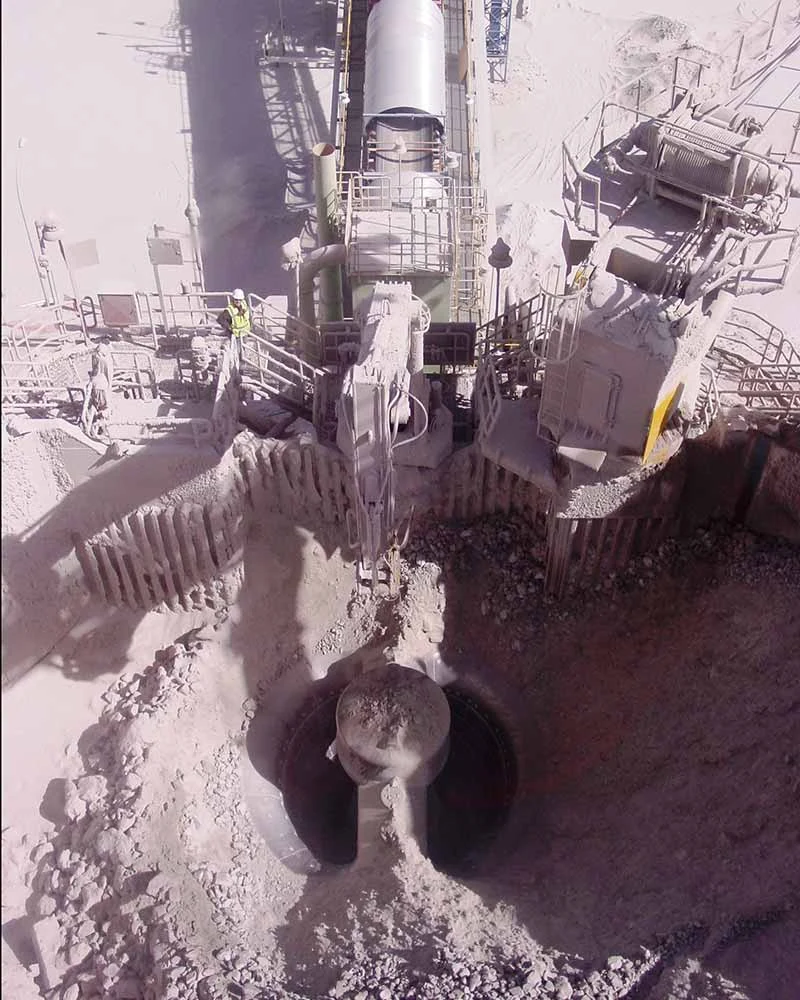
Mantle
تغطي الرأس وتشكل الحجرة مع الأغطية الثابتة (كونكيف). اختر المادة والشكل حسب الحجرة وفتحة الضبط في الجانب المغلق والمادة وتوزيع التآكل. توضح الصورة موضع التركيب.
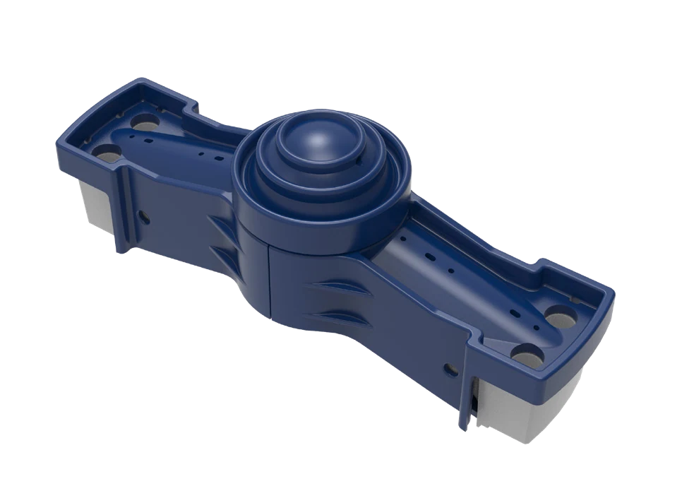
دروع أذرع العارضة العلوية
تحمي أذرع العارضة العلوية ومناطق التغذية العلوية من الصدمات المباشرة للصخور الكبيرة. تعطى الأولوية للمتانة والتوافق والتثبيت الموثوق. توضح الصورة الفئة.
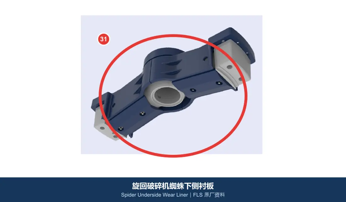
بطانات مقاومة للتآكل أسفل العارضة
تقع تحت العارضة العلوية وفوق الحجرة، وتقاوم ارتداد المادة والتعرية. ميز مناطق الصدم عن مناطق الانزلاق حسب الموضع. توضح الصورة الفئة.
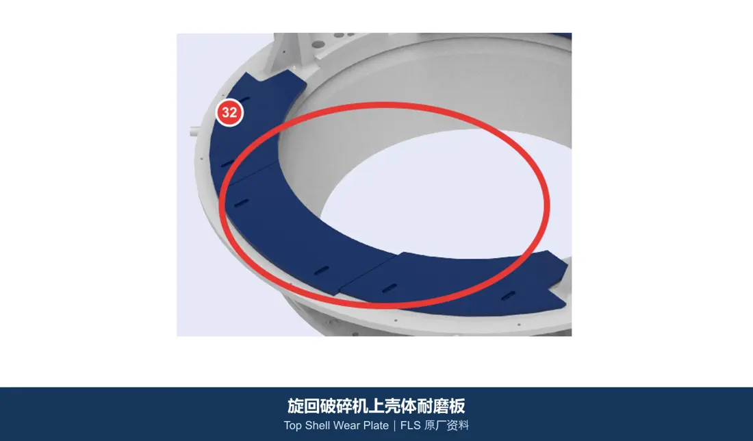
ألواح حماية الهيكل العلوي من التآكل
تحمي الأسطح الداخلية والثانوية للغلاف العلوي. اختر قطع التآكل المسبوكة أو الألواح المقساة والمراجعة حراريا أو المركبات حسب التوازن بين الصدم والسحج. توضح الصورة الفئة.
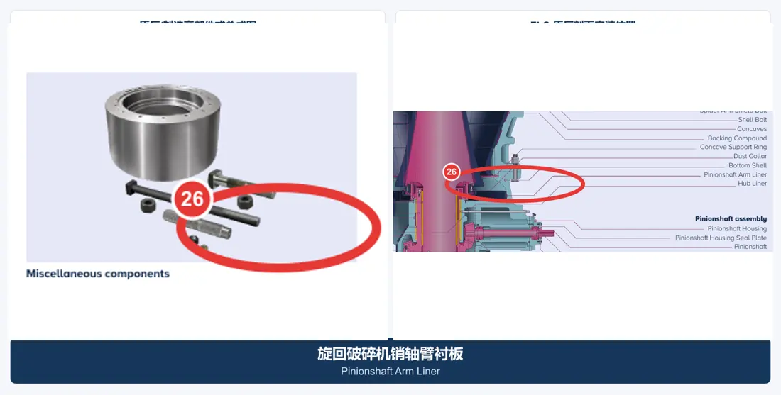
بطانات ذراع عمود الترس الصغير
تحمي الغلاف حول ذراع عمود الإدارة من صدمات التغذية الساقطة وسحج المواد الناعمة. طابق الثقوب والشكل والسماكة ومساحة الاستبدال. توضح الصورة الفئة.
حدد العارضة العلوية والعمود الرئيسي والجلبة الواقية وجلبة العارضة بصورة منفصلة. طابق اللامركز والتروس والمحامل والهيدروليك مع المجموعات المجاورة.
العارضة العلوية / مجموعة العارضة العلوية
تمتد عبر فتحة التغذية وتوجه الطرف العلوي للعمود. ميز في الاستفسار جسم العارضة والغطاء والواقيات والجلبة وأختام الإحكام والوصلات.
عرض صفحة المكون العامة →العمود الرئيسي
قطعة مستقلة حاملة للأحمال من فولاذ مطروق تدعم الرأس وتنقل أحمال الحركة الدوارة. طابق أعناق العمود والمخاريط والسنون الملولبة والمادة والمعالجة الحرارية والفحص غير الإتلافي.
عرض صفحة المكون العامة →
جلبة حماية العمود الرئيسي
قطعة حماية مستقلة حول العمود تختلف عن العمود نفسه، ويقدم عرض سعرها بصورة منفصلة عن المجموعة. طابق مناطق التوافق والتداخل ومتطلبات السطح.
عرض صفحة المكون العامة →جلبة العارضة العلوية
تقع في مركز العارضة العلوية وتوجه الطرف العلوي للعمود. تذكر المراجع الرسمية لبنية MKIII جلبة من برونز المنغنيز. طابق المادة والخلوص ومجاري الزيت والتراكز معا.
عرض صفحة المكون العامة →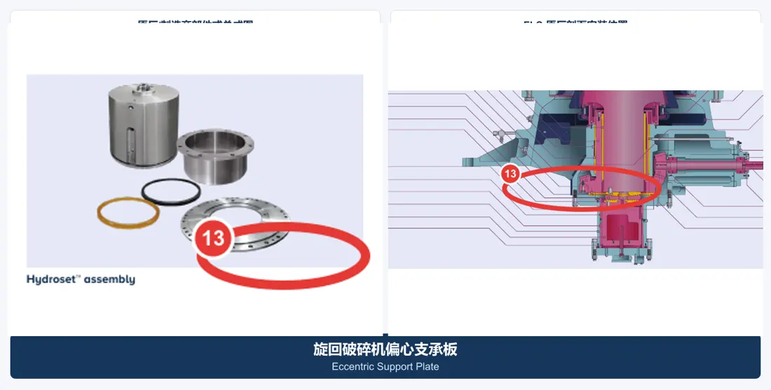
مجموعة اللامركز & الجلب
تحرك العمود والرأس بحركة دوارة. تشمل جسم اللامركز والجلبة والترس وقطع التآكل المحورية وواجهات التزييت المجاورة. توضح الصورة الفئة.
عرض صفحة المكون العامة →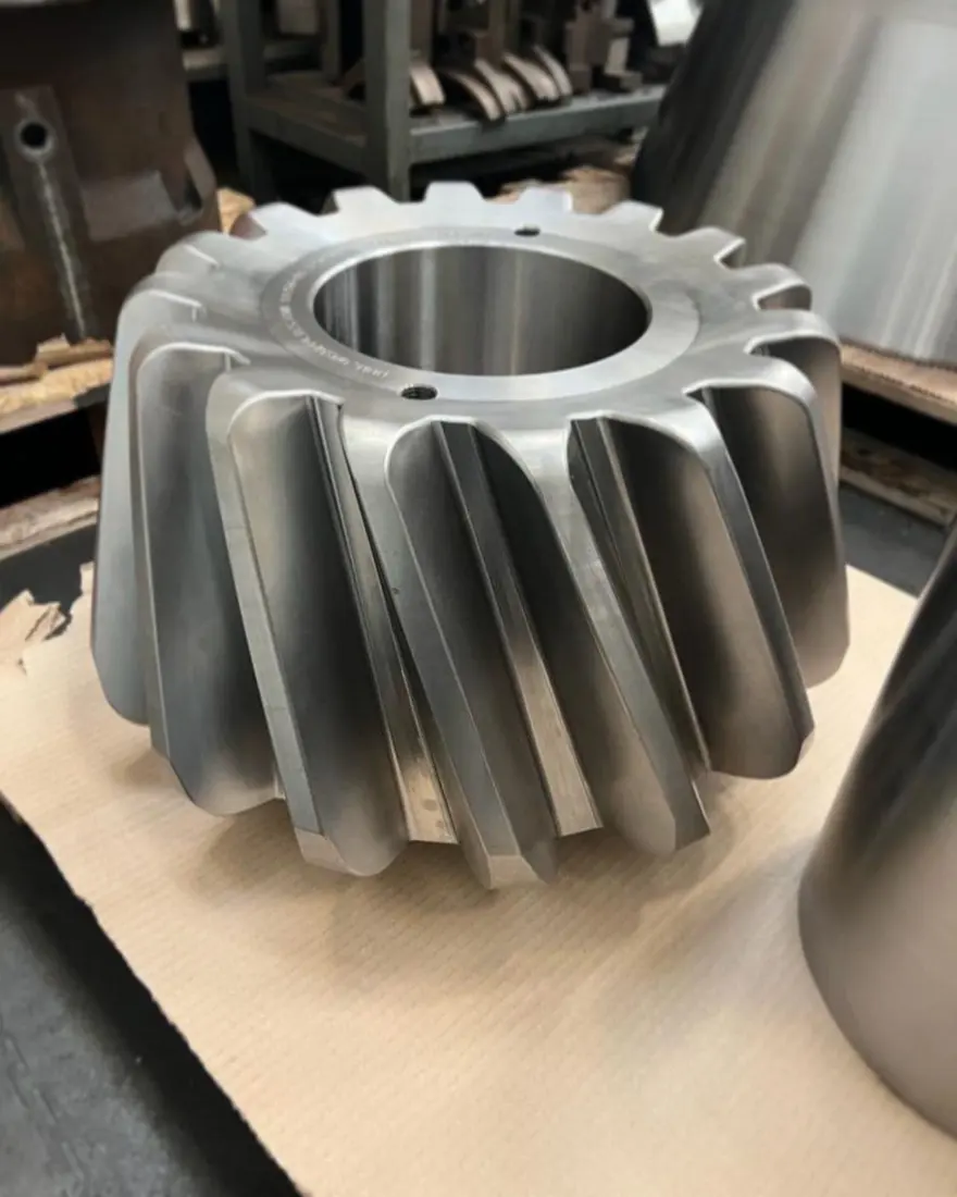
طقم الترس & الترس الصغير
تنقل عزم الدوران إلى اللامركز. تعامل مع زوج التروس كنظام متوافق؛ طابق نظام الأسنان والمادة والمعالجة الحرارية والتلامس والخلوص بين الأسنان. توضح الصورة الفئة.
عرض صفحة المكون العامة →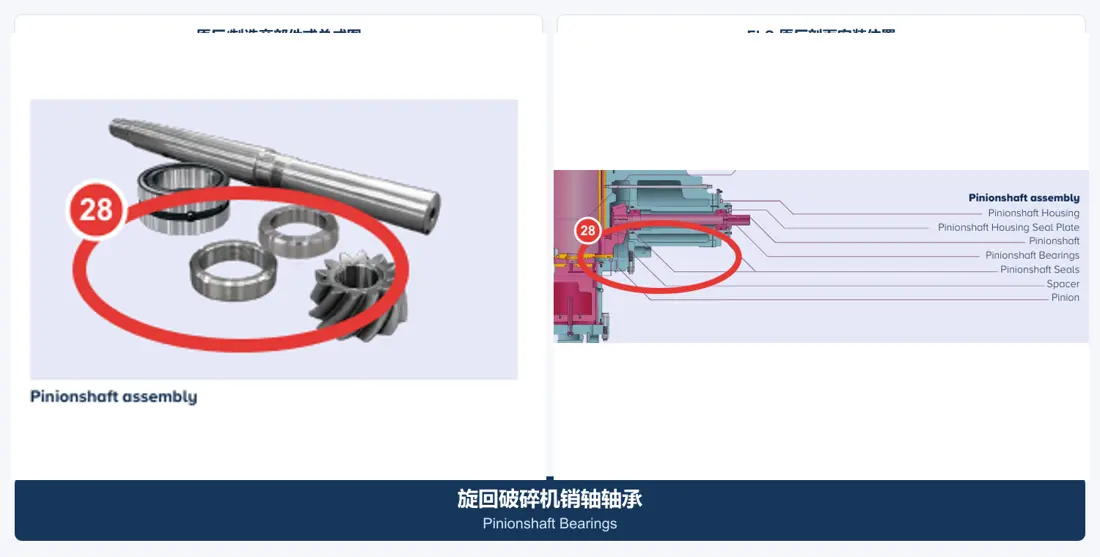
عمود الترس الصغير & المحامل
تشمل العمود والمحامل والأغلفة وأختام الإحكام. طابق المجموعة مع اقتران التروس والمسافة بين المحاور والتزييت وخلوص المحامل. توضح الصورة الفئة.
عرض صفحة المكون العامة →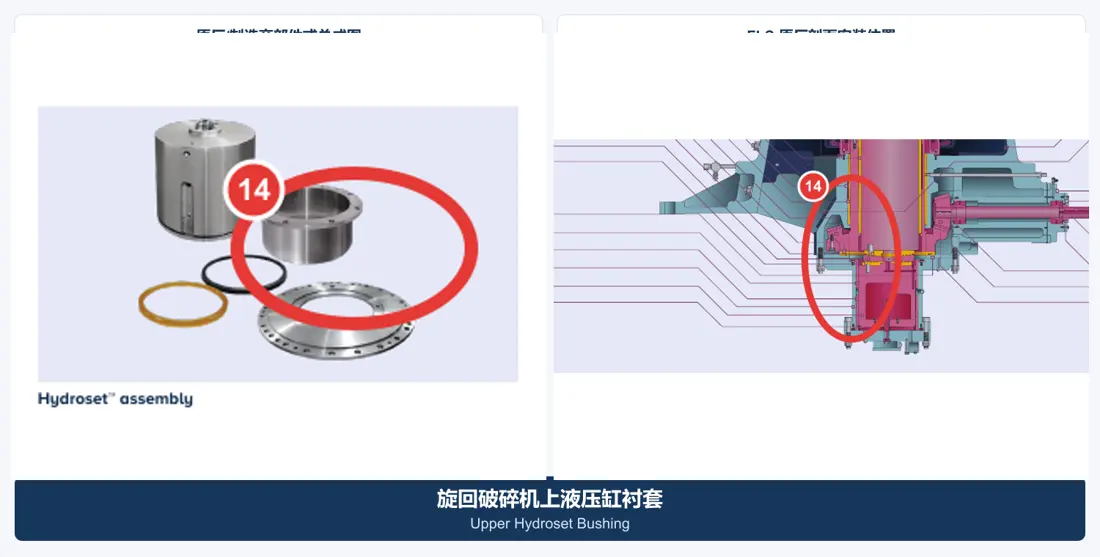
جلب Hydroset & أختام الإحكام
تشمل جلب الأسطوانة العلوية/السفلية وأختام إحكام المكبس وواجهات الضبط. طابق الضغط ودرجة الحرارة والزيت الهيدروليكي والخلوص ومقطع ختم الإحكام. توضح الصورة الفئة.
عرض صفحة المكون العامة →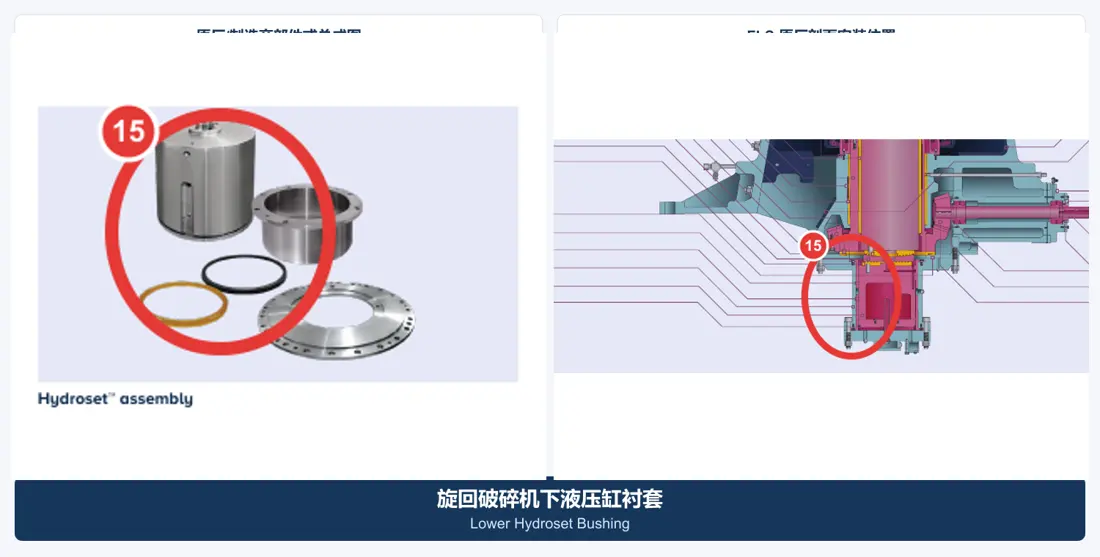
جلبة الهيكل السفلي
تقع في منطقة الدعم والانزلاق في الغلاف السفلي. طابق درجة سبيكة النحاس وجودة السباكة بالطرد المركزي وقطر التجويف والأسطوانية ومجاري الزيت وخلوص التشغيل معا. توضح الصورة الفئة.
عرض صفحة المكون العامة →تعرض فقط هياكل الصيانة الواردة في مراجع Metso. يتطلب توريد الأدوات أو تخصيصها تقييم التكوين والوزن ونقاط الرفع ومساحة الصيانة.
تذكر Metso فصل الغلاف هيدروليكيا ورفعه بصورة مستقلة في MKIII. طابق طريقة العمل في الموقع مع الواجهات الفعلية ونقاط الرفع والوزن ومساحة الصيانة.
توضح المخططات الرسمية فواصل الغلاف وفتحات الفحص، وتوفر مرجعا أوليا لواجهات الأدوات وتسلسل الفك وتخطيط السلامة.
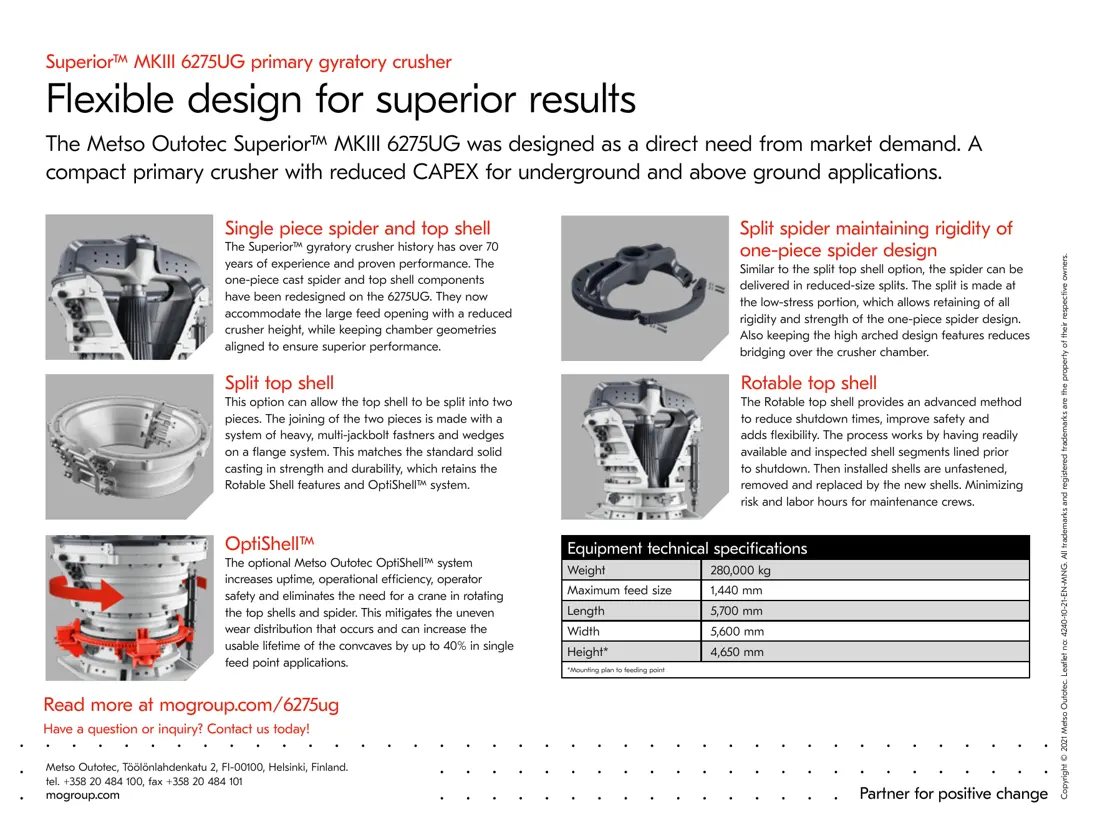
تسرد مراجع 6275UG نظام OptiShell™ الاختياري لتدوير الغلاف العلوي والعارضة العلوية. طابق ملاءمته لآلة موجودة حسب التكوين والواجهات الرسمية.
الطراز الكامل والرقم التسلسلي ومرجع المجموعة/القطعة وأحدث رسم وصور القطعة الحالية والمادة والأبعاد الرئيسية والمادة المعالجة وتفاصيل التلف.
لا. العمود قطعة مطروقة داخلية حاملة للأحمال؛ والجلبة قطعة حماية خارجية مستقلة. حدد كل واحدة وقسها وقدم عرض سعرها بصورة منفصلة.
يقتصر دور الطراز على تضييق النطاق. تحتاج البطانات إلى مطابقة الحجرة؛ وتتطلب التروس والجلب أيضا الرسم ونظام الأسنان والتوافقات والمادة والرقم التسلسلي والمراجعة.
تصفح أوصاف المكونات ومتطلبات الرسومات وبيانات الاستفسار.
قدم لوحة البيانات والرقم التسلسلي والصور والرسومات والمادة وظروف التشغيل للتعرف على القطعة وتقييم المادة والتصنيع في مسابك معتمدة ومراقبة الجودة والتسليم.
أو تواصل معنا مباشرة: +86 156 3797 3199
zzx@anranst.com
تقدّم ANRANST لعملائها حول العالم التقييم الهندسي والإنتاج في مسابك معتمدة وفق المتطلبات الفنية للعميل ومراقبة الجودة وتسليم القطع الجاهزة لقطع التآكل المخصّصة وقطع الغيار الصناعية، مع إمكانية دعم قطع صناعية مخصّصة أخرى.
نراجع أسطح التزاوج وأبعاد الوصلات، ونقيّم إمكانية التصنيع من حيث المادة والمعالجة الحرارية.
Material grades and heat-treatment processes are specified order by order, stated in the technical agreement and tracked through production.
تأكيد الرسم، ومراقبة المواد والعمليات، ومتابعة الإنتاج، والفحص، وتنسيق القبول.
ننسّق التصنيع وتأكيد الجودة والتغليف والتسليم للقطع الكاملة ضمن سلسلة توريد متكاملة وعملية.
Provide the equipment brand, complete model and serial number, part name, part number or drawing number, drawing revision, quantity, material requirements and duty. If identifiers are unavailable, send photographs and key dimensions.
أرسل استفساراً