Metso مطحنة الطحن عالية الكثافة HIGmill™

Identify HIGmill installations and assess materials and drawing-based supply for GrindForce grinding rotors, stator rings, shell liners, main shafts and drive spares.

Metso HIGmill High-Intensity Grinding Mill
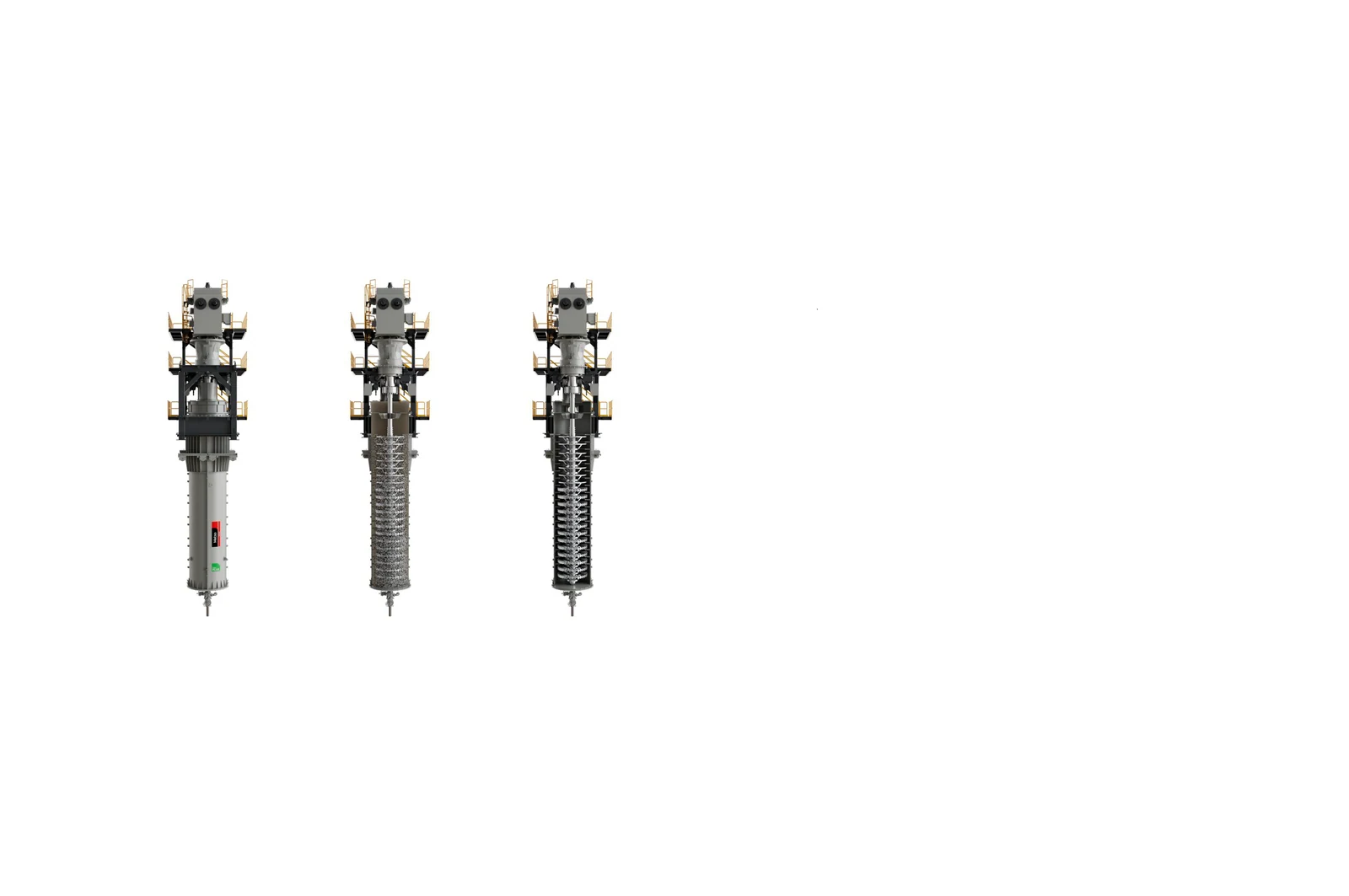
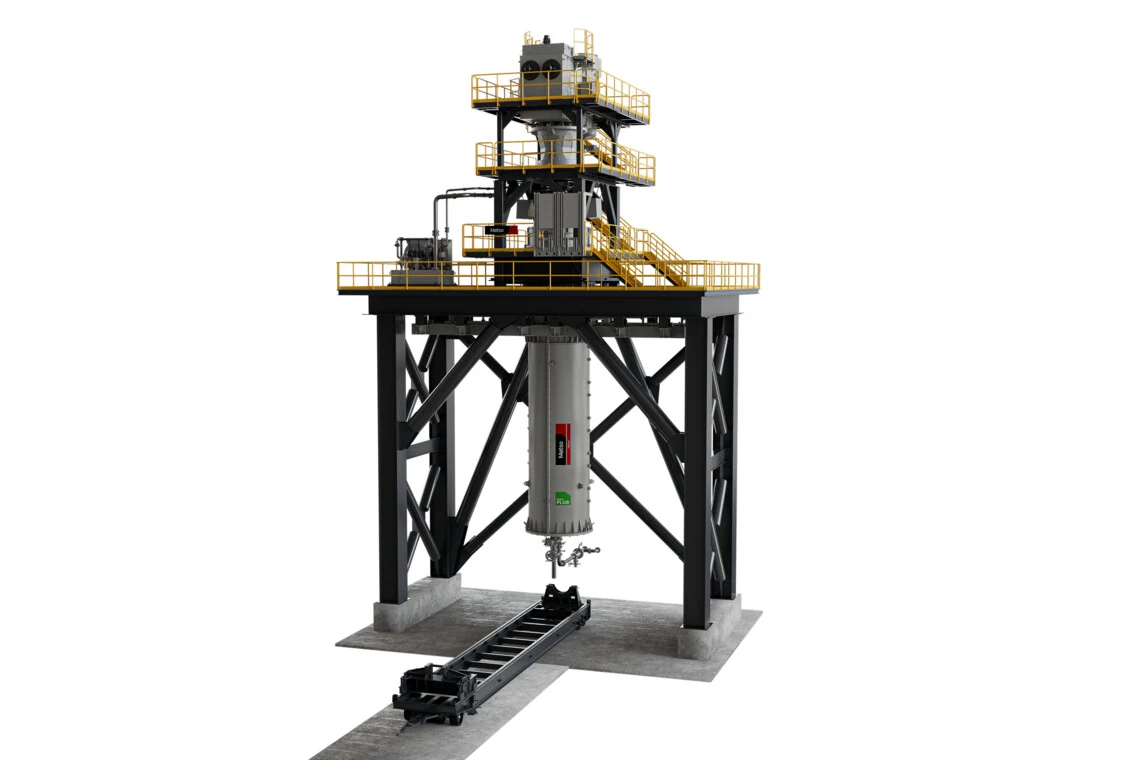
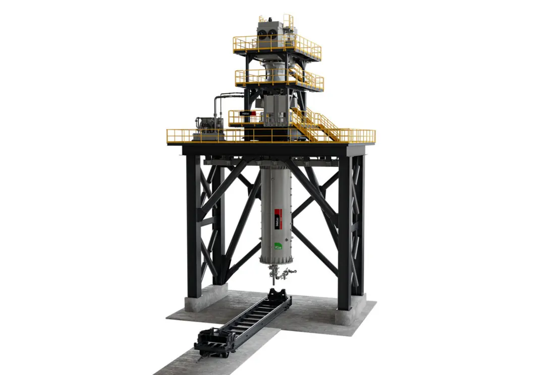
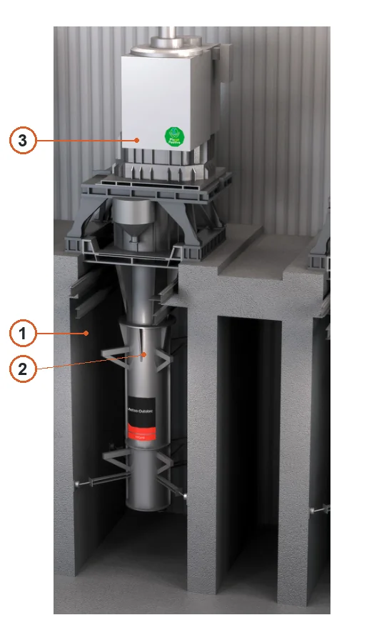
Metso HIGmill high-intensity grinding mill showing the vertical body, top drive and installation platform.
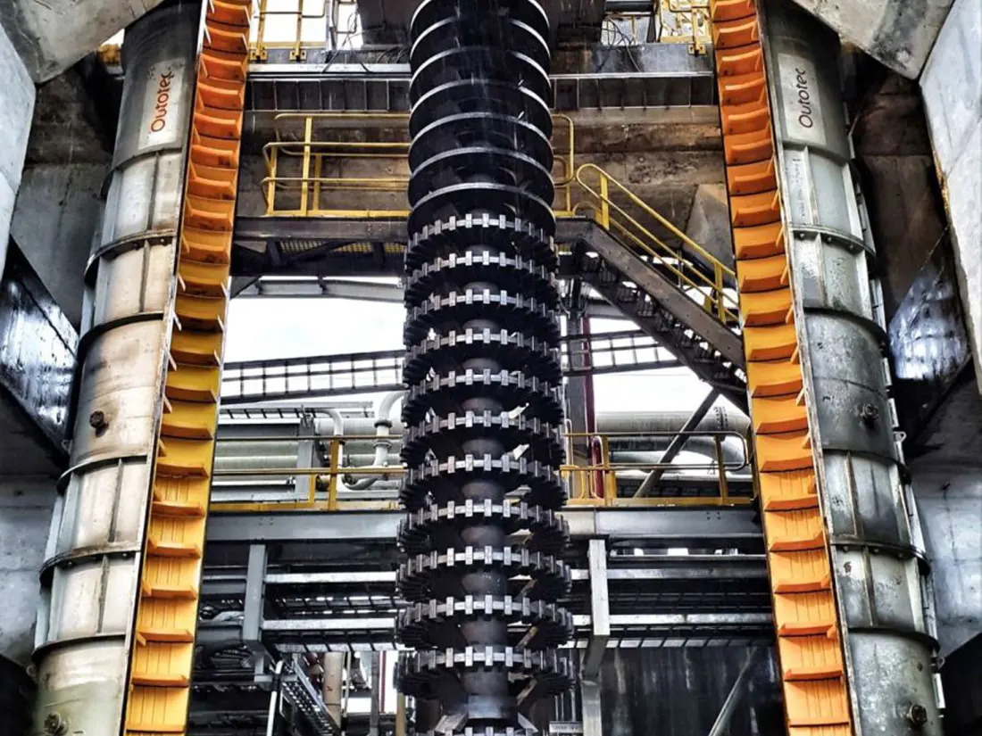
Metso HIGmill grinding rotor and mill body installation area
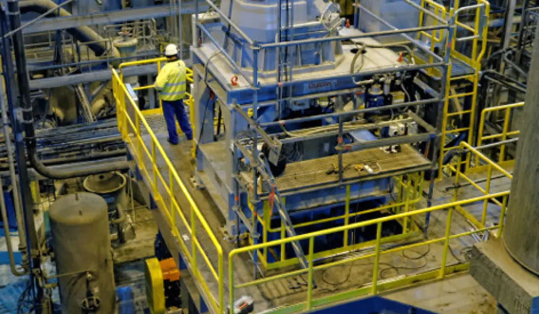
HIGmill grinding rotor during maintenance, showing rotor stages, the mill body installation area and wear locations.
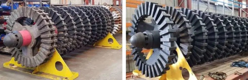
Metso HIGmill GrindForce grinding rotor assembly
HIGmill grinding rotor assembly from Metso's Sunrise Dam case study, illustrating rotor stages, shaft interfaces and wear positions. Confirm dimensions from installation drawings.
خط إنتاج المعدات الأصلية الذي يصنع هذا النوع من المعدات

Models, Grinding Chamber Design and Parts Identification

HIGmill is a vertical stirred mill for fine grinding, ultrafine grinding and regrinding. Its design comprises a mill body, main shaft with grinding rotors, shell-mounted stator rings, gearbox and drive. Feed enters at the bottom and passes upwards through successive grinding stages.

HIGmill™ Metso / Swiss Tower Mills
6,500 kW Industrial installation power on the current Metso product page
50,000 L Published Maximum Chamber Volume
20 Maximum Number of Grinding Stages
Models and Key Dimensions

HIGmill Models and Published التركيبات

The range specifications describe overall equipment capabilities. The named models below relate to published installations or pilot trials. Confirm spare parts against the nameplate, serial number, drawing number, general arrangement and drawing revision.

Series / Model Published Power / Configuration Size / Identification Requirements
HIGmill Industrial Range Unit power up to 6,500 kW Chamber volume up to 50,000 L; confirm model and dimensions from project records, nameplate or drawings
HIG3500/23000 3,500 kW; published installation 23,000 L; Sunrise Dam البند
HIG500/4000 500 kW; published installation 4,000 L; Cracow project, with a footprint of approximately 2.7 m × 2.3 m
HIG25 Pilot المعدات Cracow site pilot trials; specify power and dimensions from the equipment records
HIG5 Test المعدات Sunrise Dam scale-up testwork; specify power and dimensions from the equipment records

Technical Information: HIGmill Product Information, HIG3500/23000 البند, HIG500/4000 البند.

قطع الغيار المستهلكة

HIGmill Grinding Rotors, Stator Rings and بطانات الجسم

Identify wear parts by grinding stage and installation position. Match candidate materials and processes to abrasion, media wear and slurry corrosion, confirming the material, design and drawing reference for the installation.

Metso HIGmill GrindForce grinding rotor assembly
01

GrindForce Grinding Rotors

GrindForce Grinding Rotor

Mounted along the main shaft, grinding rotors face continuous abrasion and shear from ceramic media and slurry. Lower stages can experience greater pressure and wear. Published projects include steel and rubber-covered castellated rotors. Select materials for particle size, media density, speed and drawing requirements.

المعدات range: HIGmill industrial models. Confirm drawing and part numbers for the installed model.

Explore Grinding Rotors →
HIGmill rotor and shell-mounted stator grinding stages
02

Shell-mounted Stator Rings

Shell-mounted Stator Ring

Stator rings attach inside the mill body and work with rotating rotors to form successive grinding stages and control media movement. Check stage position, internal and external diameters, thickness, segmentation, fixings and rotor clearance. Published projects include rubber-covered stationary elements.

المعدات range: HIGmill industrial models. Confirm drawing and part numbers by stage position and mill body drawings.

Explore Stator Rings →
HIGmill body and shell liner installation area
03

Shell Lining Systems

بطانة جسم الطاحونة Components

Shell liners protect the body against media and slurry wear. Conditions vary with height; check remaining thickness, segmentation, curvature and fixings in lower feed and high-pressure zones. Published cases include fully vulcanized rubber-covered stationary elements and shell linings.

المعدات range: HIGmill industrial models. Confirm drawing and part numbers by shell diameter, stage position and liner drawings.

Explore بطانات الجسم →
قطع الغيار

Main Shafts, Drive and Structural Spares

Identify drive and structural spares separately. For gearboxes, main shafts, bearings, seals and split mill bodies, confirm interfaces, tolerances, materials, heat treatment and installation drawing numbers before manufacture.

Main shaft and grinding rotor assembly in a Metso HIGmill case study
01

العمود الرئيسي ومجموعة دعم الدوار

العمود الرئيسي ومجموعة دعم الدوار

The main shaft transmits top-drive torque and supports the grinding rotors. Check overall length, shaft diameters, rotor interfaces, keys or connections, runout, heat treatment and dynamic balance. Specify the shaft alone or the complete assembly separately.

Configuration varies with HIGmill diameter and grinding stages. Confirm drawing and part numbers from the main shaft assembly drawing.

Explore Main Shafts →
HIGmill top gearbox and drive system
02

علبة التروس ومكونات القيادة

علبة التروس ومكونات القيادة

The top drive powers the vertical main shaft. Identify gears, pinion shafts, couplings, bushes and connectors from installation drawings, checking tooth profile, module, accuracy class, material, heat treatment and fits.

Identify by power and drive configuration. Confirm drawing and part numbers from the gearbox nameplate and assembly drawing.

Explore Drive Parts →
HIGmill Split Mill Bodies and Structural Parts
03

Split Mill Bodies and Structural Parts

Split Mill Body and Structural Components

HIGmill uses a flanged split mill body for maintenance access. Check diameter, section positions, flange hole patterns, concentricity, welding and nondestructive testing requirements, and stator and liner interfaces.

Configuration varies with chamber volume and diameter. Confirm drawing and part numbers from mill body assembly and section drawings.

Explore Mill Body Parts →
HIGmill main shaft support, bearing and seal installation area
04

Bearings, Sleeves and الموانع

Bearings, Sleeves and Shaft الموانع

For main shaft support, location and slurry isolation. Check bearing designations, housings, bush dimensions, lubrication, seal design, elastomer compatibility and operating temperature against installation drawings.

Identify by main shaft support and seal configuration. Confirm drawing and part numbers from bearing and seal assembly drawings.

Explore المحامل والموانع →

What information is needed to quote parts for Metso HIGmill?

يرجى توفير الطراز الكامل والرقم التسلسلي ورقم الرسم أو رقم القطعة ومراجعة الرسم وموضع التركيب وصور القطعة الحالية والمادة وظروف التشغيل.

Can equipment and part photographs be used directly for manufacturing?

No. Photographs help identify equipment and part types. Manufacturing requires confirmed drawings, dimensions, interfaces, materials, heat treatment and acceptance criteria.

هل يمكن تقييم القطعة دون رقم رسم من الشركة المصنعة الأصلية؟

Start with the nameplate, general arrangement drawing, installation position, photographs of the existing part and critical dimensions. These support assessment of measurement, material selection and drawing-based manufacturing requirements.

Send Your HIGmill Model or Drawing

Provide the full model, serial number, nameplate, part position, photographs of the existing part, drawings, material and operating conditions. These support identification, material assessment, manufacturing coordination, quality control and finished-part delivery.

طلب مراجعة المشروع

رقم الهاتف: +86 156 3797 3199
zzx@anranst.com

خدمات صنع في الصين

من التقييم الفني إلى تسليم المنتج بالكامل

توفر شركة ANRANST للعملاء العالميين تقييمات هندسية، واختيار التصنيع الصيني، ومراقبة الجودة، وتسليم الأجزاء النهائية لقطع الغيار الصناعية المقاومة للتآكل حسب الطلب، ويمكنها أيضًا دعم قطع الغيار الصناعية الأخرى حسب الطلب.

01

مراجعة الرسومات والهندسة

قم بمراجعة أسطح التزاوج وأبعاد الواجهة، وقم بتقييم جدوى المواد والمعالجة الحرارية والتصنيع.

02

تحديد المادة والمعالجة الحرارية

تُحدَّد درجات المواد وعمليات المعالجة الحرارية لكل طلب على حدة، وتُثبَّت في الاتفاقية الفنية وتُتابَع أثناء الإنتاج.

03

ضبط الجودة

يشمل ذلك تأكيد الرسم، ومراقبة المواد والعمليات، وتتبع الإنتاج، وتنسيق عمليات الفحص والقبول.

04

تسليم المنتج النهائي

تنظيم عمليات التصنيع والتحقق من الجودة والتعبئة والتغليف وتسليم المنتجات النهائية الكاملة لتشكيل حلقة إمداد قابلة للتنفيذ.

قم بتزويدنا بالنماذج الحالية، والرسومات، وأرقام الرسومات، وأرقام الأجزاء، والمواد، أو معلومات ظروف التشغيل، وسنقوم بتحديد التحقق الفني ومسار التوريد وفقًا لذلك.

إرسال طلب