
01
Mantle
Mantle
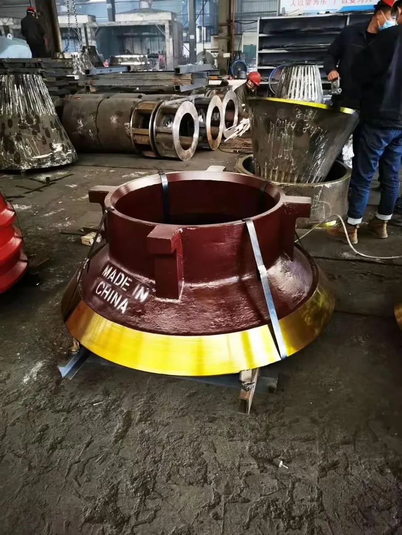
Mounted over the mainshaft and head, the mantle forms the varying chamber with the concaves. Confirm profile, segments, thickness, fixing and wear allowance for the full KB / BK model.
View the common part page →Identify legacy KB gyratory and BK jaw-gyratory installations, the current FLS Pro range, wear parts, structural spares and dedicated maintenance tools.
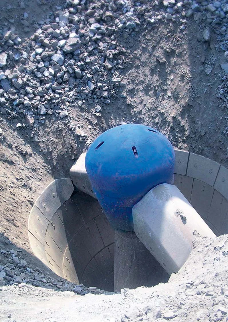
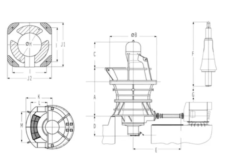
KB uses an annular feed opening; BK uses a jaw-gyratory arrangement with an enlarged opening on one side. This page brings together models, dimensions, wear and drive parts, materials and documented tools needed for spares supply.
The table follows the thyssenkrupp gyratory brochure, supplemented by the FLS 2023 data sheet for KB 63-130 Pro. Weight and capacity depend on configuration and serve installation identification only.
| Standard model | Feed opening / mantle diameter | Principal drive and setting data | Reference machine weight |
|---|---|---|---|
| KB 54-67 | Feed opening 1370 mm; mantle 1700 mm | Up to 450 kW; eccentric approx. 137 rpm | Approx. 180 t |
| KB 54-75 | Feed opening 1370 mm; mantle 1900 mm | Up to 650 kW; eccentric approx. 137 rpm | Approx. 215 t |
| KB 63-75 | Feed opening 1600 mm; mantle 2030 mm | Up to 650 kW; eccentric approx. 137 rpm | Approx. 270 t |
| KB 63-89 | Feed opening 1600 mm; mantle 2260 mm | Up to 1000 kW; eccentric approx. 130 rpm | Approx. 332 t |
| KB 63-114 | Feed opening 1600 mm; mantle 2900 mm | Up to 1200 kW; eccentric approx. 127 rpm | Approx. 530 t |
| KB 63-130 / KB 63-130 Pro | Feed opening 1600 mm; mantle 3300 mm | Up to 1500 kW; OSS 170–300 mm | Approx. 495 t |
| BK 54-67 | One-sided opening 2640 × 1350 mm; mantle 1700 mm | Up to 450 kW; eccentric approx. 137 rpm | Approx. 175 t |
| BK 63-75 | One-sided opening 3080 × 1680 mm; mantle 1900 mm | Up to 650 kW; eccentric approx. 137 rpm | Approx. 209 t |
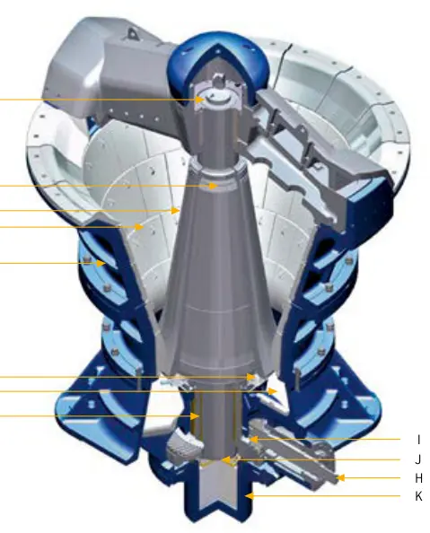
The numbers on the diagram correspond one to one with the rows below.
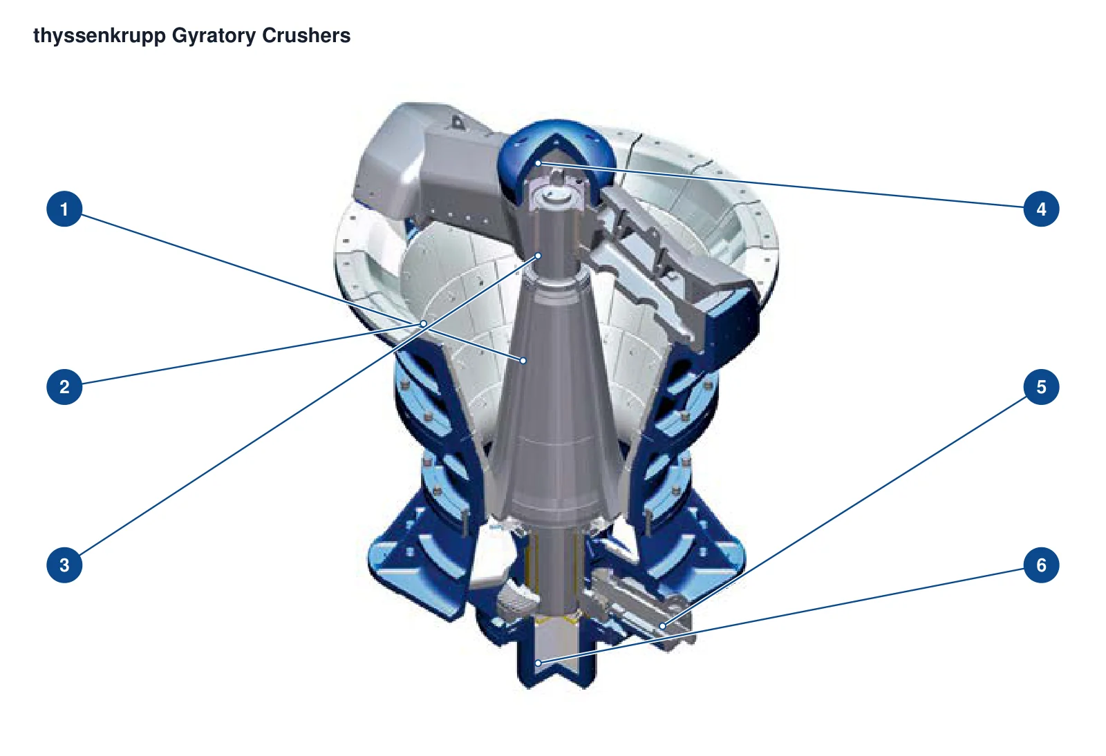
| No. | Component | Location | Applies to |
|---|---|---|---|
| 1 | Mantle | Conical crushing face around the central shaft | OEM family section; exact KB/BK dimensions not specified |
| 2 | Concave segments | Tiered working faces inside the left shell | OEM family section; exact KB/BK dimensions not specified |
| 3 | Main shaft | Central vertical shaft through the cone | OEM family section; exact KB/BK dimensions not specified |
| 4 | Main shaft suspension | Central support in the upper spider | OEM family section; exact KB/BK dimensions not specified |
| 5 | Countershaft | Lower horizontal shaft on the right | OEM family section; exact KB/BK dimensions not specified |
| 6 | Hydraulic support | Adjustment support beneath the central shaft | OEM family section; exact KB/BK dimensions not specified |
Mantles, concaves, mainshaft sleeves, spider-arm shields, underside liners and top-shell wear plates are identified separately by position and linked to component and material pages.
Mantle
Mounted over the mainshaft and head, the mantle forms the varying chamber with the concaves. Confirm profile, segments, thickness, fixing and wear allowance for the full KB / BK model.
View the common part page →Concave Segment
Segments inside the top shell form the chamber with the mantle. Check count, zonal profiles, backing gaps, support rings and adjacent interfaces together.
View the common part page →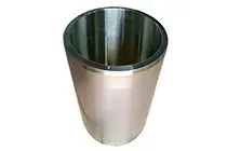
Mainshaft Protective Sleeve
This separate protective part fits outside the mainshaft; it is not the shaft itself. Confirm diameters, length, locating shoulders, removal direction and fit with the head separately.
View the common part page →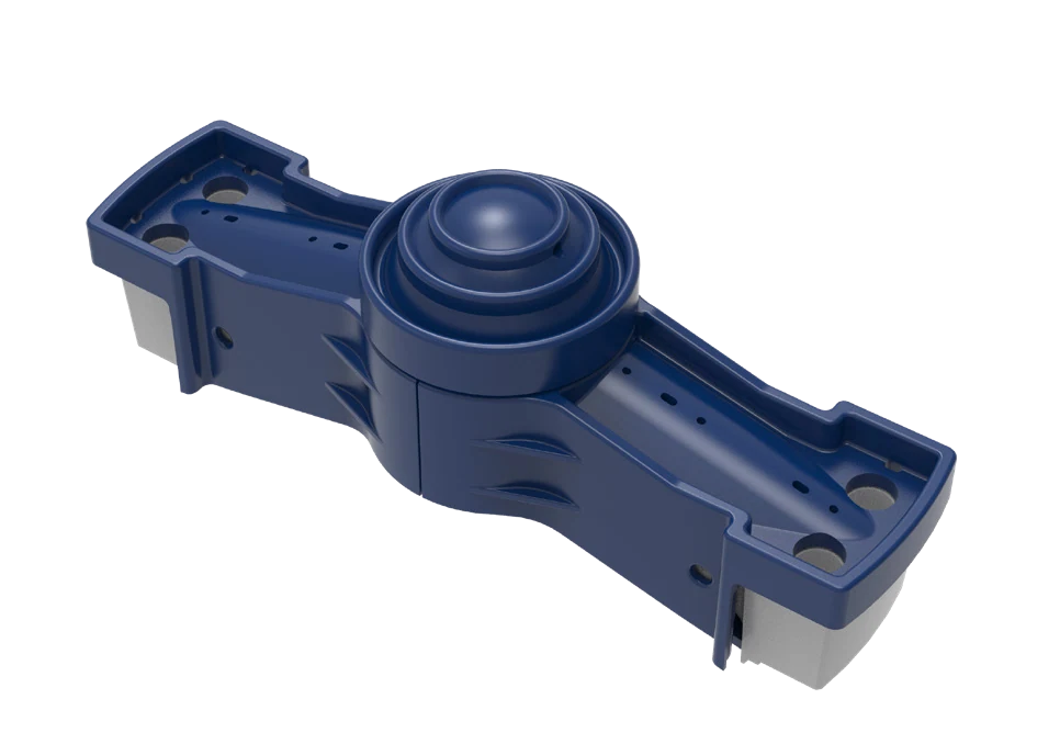
Spider Arm Shield
Shields cover feed-facing spider arms against falling-material impact and erosion. Confirm handedness, arm profile, overlaps, holes and wear direction from the spider design.
View the common part page →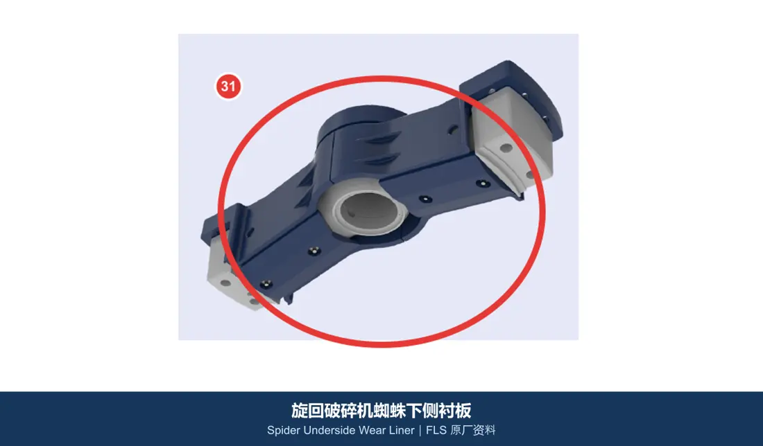
Spider Underside Wear Liner
Located under the spider near the feed and chamber top, these require joint checks of profile, countersunk holes, handedness and mainshaft oscillation clearance.
View the common part page →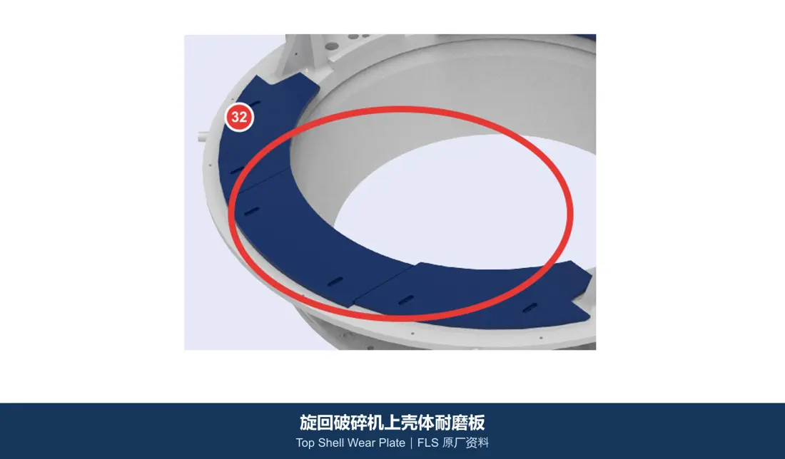
Top Shell / Feed Area Wear Plate
These protect the top shell, hopper and adjacent feed chute. Identify by drop point, lump size, liner zones, holes, overlaps and maintenance access.
View the common part page →The mainshaft and protective sleeve are separate parts. Confirm spider, shaft and eccentric assemblies, gears, upper bushes and hydraulic adjustment by their own interfaces and materials.
Spider Assembly
The spider carries the upper mainshaft support and defines feed passages. Standard ring, split-ring, bone-shaped and jaw-type designs differ in structure, weight, support and removal method; confirm the installed version.
View the common part page →Mainshaft Assembly
The mainshaft is the complete load-bearing shaft, separate from its protective sleeve. The assembly also involves the head, head nut, step-bearing interface and hydraulic support end.
View the common part page →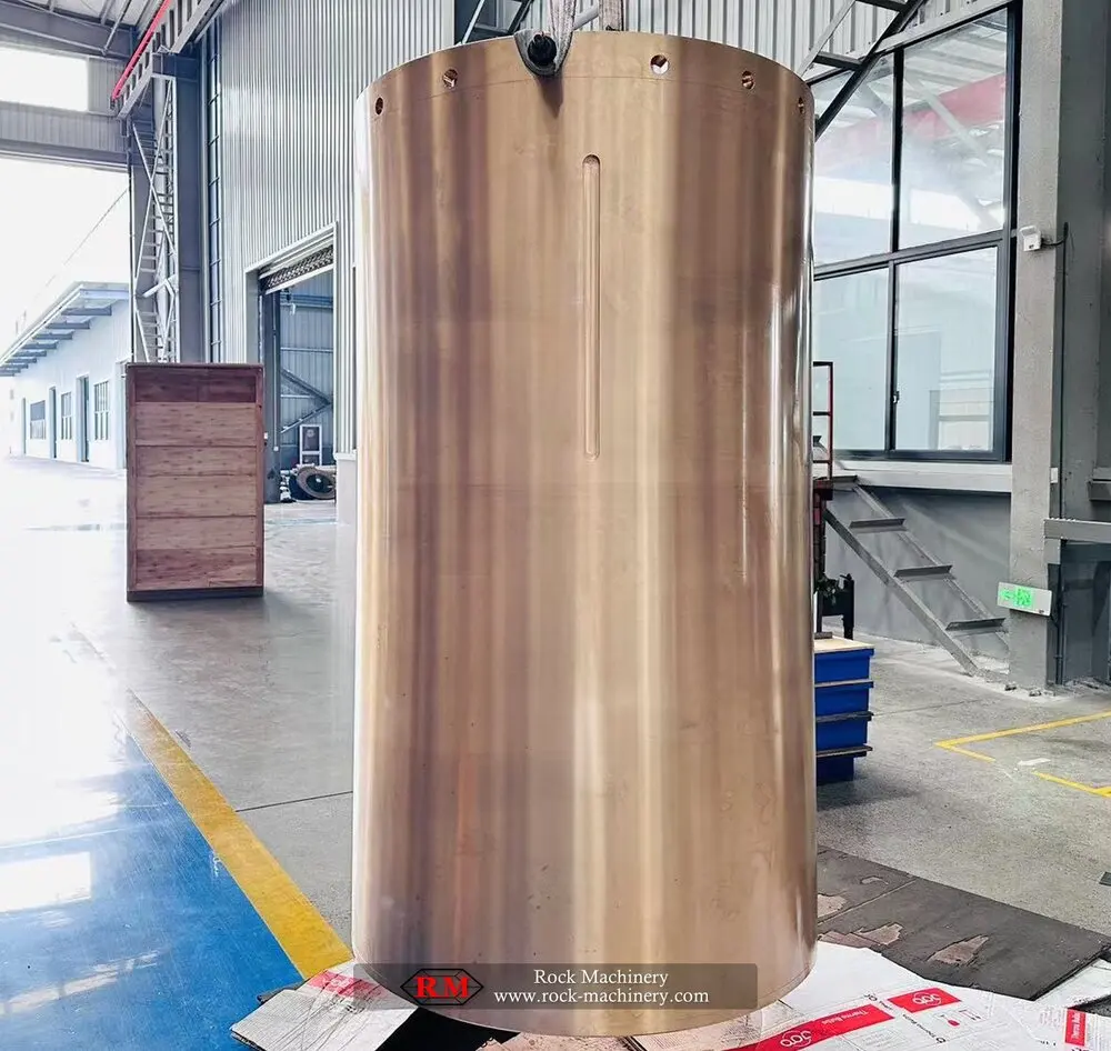
Eccentric Assembly & Bushing
The eccentric drives mainshaft gyration and includes the body, inner bush, counterweight and supports. Confirm eccentricity, diameters, oil grooves, rotation direction and stroke setting by model.
View the common part page →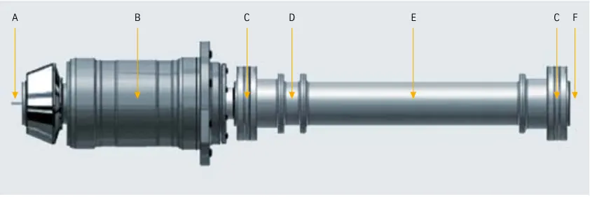
Bevel Gear & Pinion
The OEM uses cyclo-palloid spiral bevel gearing. Confirm tooth counts, module, pressure angle, spiral hand, shaft angle, backlash and matching marks as a pair.
View the common part page →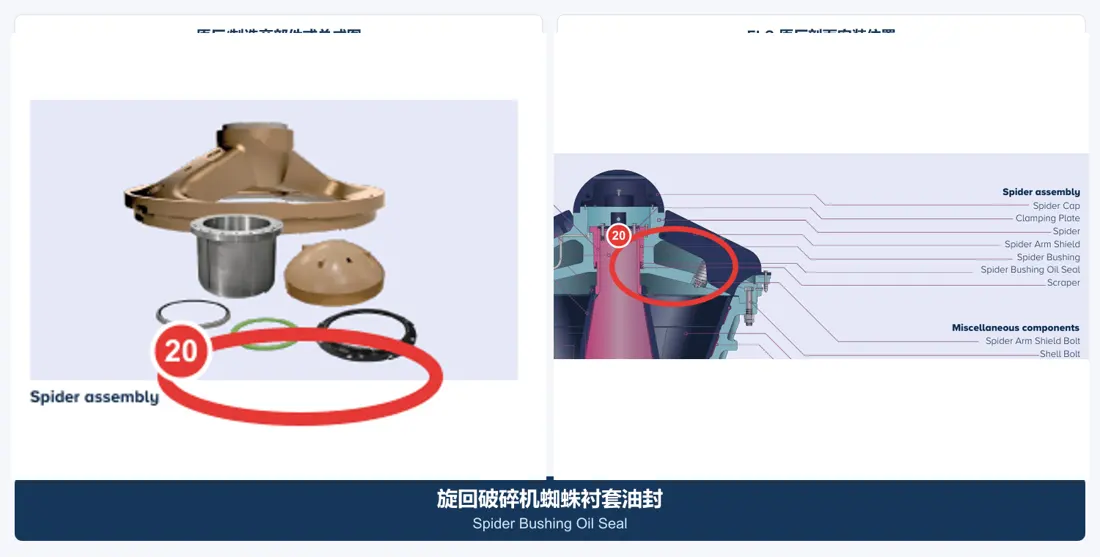
Spider Bushing & Oil Seal
At the spider centre, these support upper-mainshaft movement. Check bore, length, oil grooves, clearance, lubrication and seal orientation with the shaft journal.
View the common part page →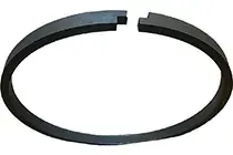
Hydraulic Adjustment & Piston Seal
Hydraulics support and raise/lower the mainshaft to set discharge gap, compensate wear and protect against overload. Check bore, stroke, pressure, seal grooves and step-bearing interface together.
View the common part page →No. BK has a jaw-gyratory structure with an enlarged one-sided opening, so its spider, housing, chamber and feed area differ from KB. Confirm full model, serial number and drawings.
No. The mainshaft is a large internal load-bearing forging; the sleeve is a separate protective part fitted outside it. Materials, dimensions, manufacturing and acceptance requirements differ.
Existing internal tooth-cap records cannot reliably link numbers to specific KB / BK positions and drawing revisions, so no numbers are inferred. Establish the link after receiving nameplate or drawing.
Provide model, Pro configuration, serial number, opening, mantle diameter, drawings, photos, dimensions, materials and duty. We coordinate identification, material assessment, manufacture, quality control and delivery.
Or contact us directly: +86 156 3797 3199
zzx@anranst.com
ANRANST provides customers worldwide with engineering assessment, production at certified foundries to the customer technical requirements, quality control and finished-part delivery for custom wear parts and industrial spares, with scope to support other custom industrial parts.
We review mating surfaces and interface dimensions and assess material, heat treatment and manufacturing feasibility.
Material grades and heat-treatment processes are specified order by order, stated in the technical agreement and tracked through production.
Drawing confirmation, material and process control, production tracking, inspection and acceptance coordination.
We coordinate manufacturing, quality confirmation, packaging and delivery of complete finished parts in a workable, closed-loop supply process.
Provide the existing model, drawings, drawing, materials or operating conditions so we can identify the appropriate technical review and supply route.
Submit an Enquiry