
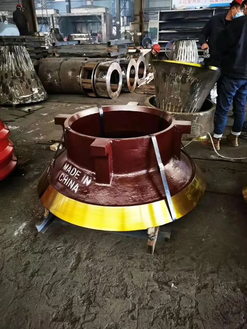
01
Mantle
Mantle
يركب فوق العمود الرئيسي والرأس ويشكل مع بطانات الحجرة الثابتة حجرة متغيرة. طابق المقطع والقطاعات والسماكة والتثبيت وسماحية التآكل للطراز الكامل KB / BK.
عرض صفحة الجزء المشترك →حدد تجهيزات KB الدوارة وBK الفكية الدوارة التاريخية ونطاق FLS Pro الحالي وقطع التآكل وقطع الغيار الهيكلية وأدوات الصيانة المخصصة.
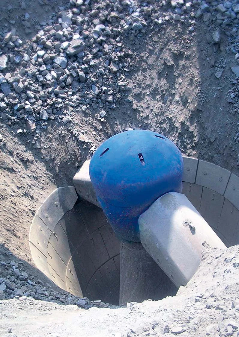
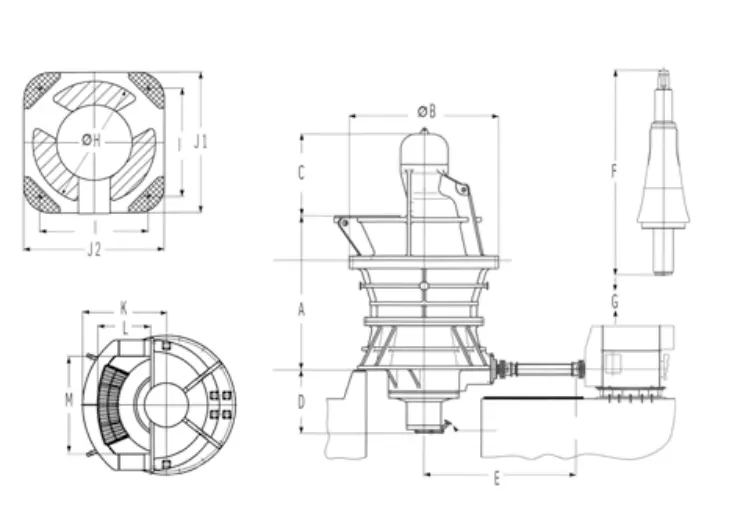
تستخدم KB فتحة تغذية حلقية؛ وتستخدم BK بنية فكية دوارة بفتحة موسعة من جانب واحد. تجمع الصفحة الطرازات والأبعاد وقطع التآكل والإدارة والمواد والأدوات الموثقة اللازمة لتوريد قطع الغيار.
يتبع الجدول كتيب كسارات thyssenkrupp الدوارة، مع بيانات إضافية من ورقة FLS لعام 2023 للطراز KB 63-130 Pro. يعتمد الوزن والإنتاجية على التجهيز ويخدمان تحديد المعدات المركبة فقط.
| الطراز القياسي | فتحة التغذية / قطر المانتل | بيانات الإدارة والضبط الرئيسية | وزن المعدة المرجعي |
|---|---|---|---|
| KB 54-67 | فتحة التغذية 1370 mm؛ المانتل (المخروط المتحرك) 1700 mm | حتى 450 kW؛ اللامركزي نحو 137 rpm | نحو 180 t |
| KB 54-75 | فتحة التغذية 1370 mm؛ المانتل (المخروط المتحرك) 1900 mm | حتى 650 kW؛ اللامركزي نحو 137 rpm | نحو 215 t |
| KB 63-75 | فتحة التغذية 1600 mm؛ المانتل (المخروط المتحرك) 2030 mm | حتى 650 kW؛ اللامركزي نحو 137 rpm | نحو 270 t |
| KB 63-89 | فتحة التغذية 1600 mm؛ المانتل (المخروط المتحرك) 2260 mm | حتى 1000 kW؛ اللامركزي نحو 130 rpm | نحو 332 t |
| KB 63-114 | فتحة التغذية 1600 mm؛ المانتل (المخروط المتحرك) 2900 mm | حتى 1200 kW؛ اللامركزي نحو 127 rpm | نحو 530 t |
| KB 63-130 / KB 63-130 Pro | فتحة التغذية 1600 mm؛ المانتل (المخروط المتحرك) 3300 mm | Up to 1500 kW; OSS 170–300 mm | نحو 495 t |
| BK 54-67 | فتحة من جانب واحد 2640 × 1350 mm؛ المانتل 1700 mm | حتى 450 kW؛ اللامركزي نحو 137 rpm | نحو 175 t |
| BK 63-75 | فتحة من جانب واحد 3080 × 1680 mm؛ المانتل 1900 mm | حتى 650 kW؛ اللامركزي نحو 137 rpm | نحو 209 t |
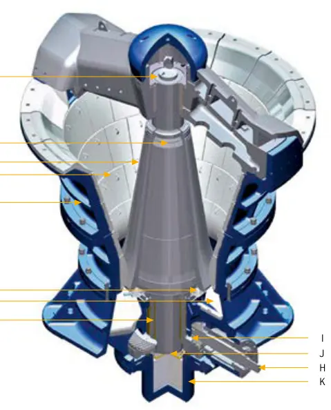
تتطابق الأرقام على المخطط مع الصفوف أدناه.
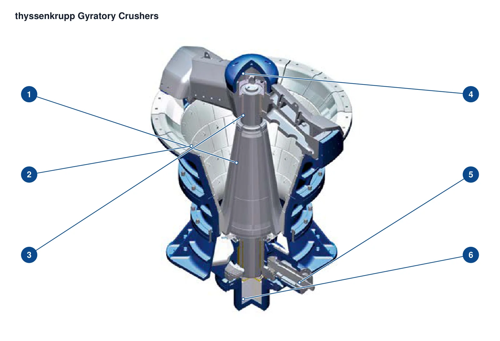
| الرقم | المكوّن | الموضع | ينطبق على |
|---|---|---|---|
| 1 | Mantle | سطح تكسير مخروطي حول العمود المركزي | مقطع عائلة OEM; أبعاد KB/BK الدقيقة غير محددة |
| 2 | قطاعات الغطاء الثابت (كونكيف) | أسطح عمل متدرجة داخل الغلاف الأيسر | مقطع عائلة OEM; أبعاد KB/BK الدقيقة غير محددة |
| 3 | العمود الرئيسي | عمود رأسي مركزي يمر عبر المخروط | مقطع عائلة OEM; أبعاد KB/BK الدقيقة غير محددة |
| 4 | نظام تعليق العمود الرئيسي | دعامة مركزية في العارضة العلوية | مقطع عائلة OEM; أبعاد KB/BK الدقيقة غير محددة |
| 5 | Countershaft | العمود الأفقي السفلي على اليمين | مقطع عائلة OEM; أبعاد KB/BK الدقيقة غير محددة |
| 6 | دعامة هيدروليكية | دعامة ضبط أسفل العمود المركزي | مقطع عائلة OEM; أبعاد KB/BK الدقيقة غير محددة |
تحدد المانتلات وبطانات الحجرة الثابتة وأكمام العمود الرئيسي وواقيات أذرع العارضة والبطانات السفلية وألواح تآكل الغلاف العلوي منفصلة بحسب الموضع، وترتبط بصفحات المكونات والمواد.
Mantle
يركب فوق العمود الرئيسي والرأس ويشكل مع بطانات الحجرة الثابتة حجرة متغيرة. طابق المقطع والقطاعات والسماكة والتثبيت وسماحية التآكل للطراز الكامل KB / BK.
عرض صفحة الجزء المشترك →قطاع الغطاء الثابت (كونكيف)
تشكل القطاعات داخل الغلاف العلوي الحجرة مع المانتل. افحص معا العدد والمقاطع بحسب المناطق وفجوات الحشو الخلفي وحلقات الدعم ومواضع التوصيل المجاورة.
عرض صفحة الجزء المشترك →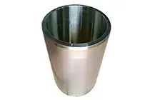
جلبة حماية العمود الرئيسي
تركب هذه القطعة الواقية المنفصلة خارج العمود الرئيسي وليست العمود نفسه. طابق الأقطار والطول وأكتاف تحديد الموضع واتجاه الفك والتوافق مع الرأس منفصلة.
عرض صفحة الجزء المشترك →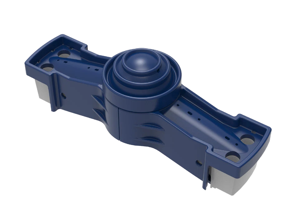
واقي ذراع العارضة العلوية
تغطي الواقيات أذرع العارضة المواجهة للتغذية لحمايتها من صدم المادة الساقطة والتعرية. حدد الجانب ومقطع الذراع والتراكبات والثقوب واتجاه التآكل من تصميم العارضة.
عرض صفحة الجزء المشترك →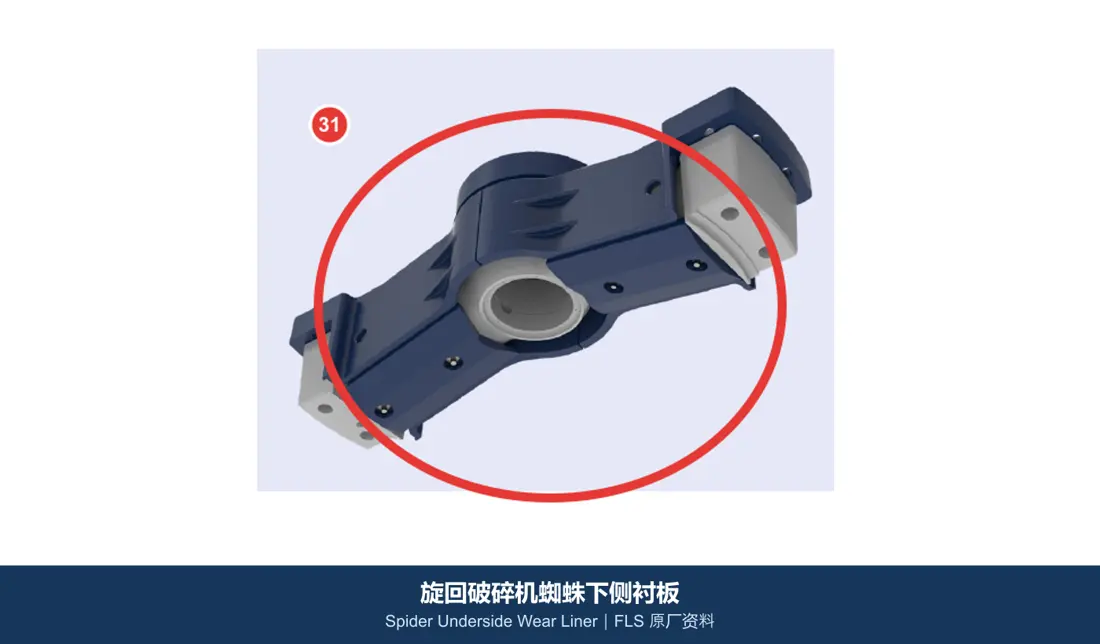
بطانة مقاومة للتآكل أسفل العارضة
تقع تحت العارضة قرب التغذية وأعلى الحجرة؛ وتتطلب فحصا مشتركا للمقطع والثقوب الغاطسة والجانب وخلوص تذبذب العمود الرئيسي.
عرض صفحة الجزء المشترك →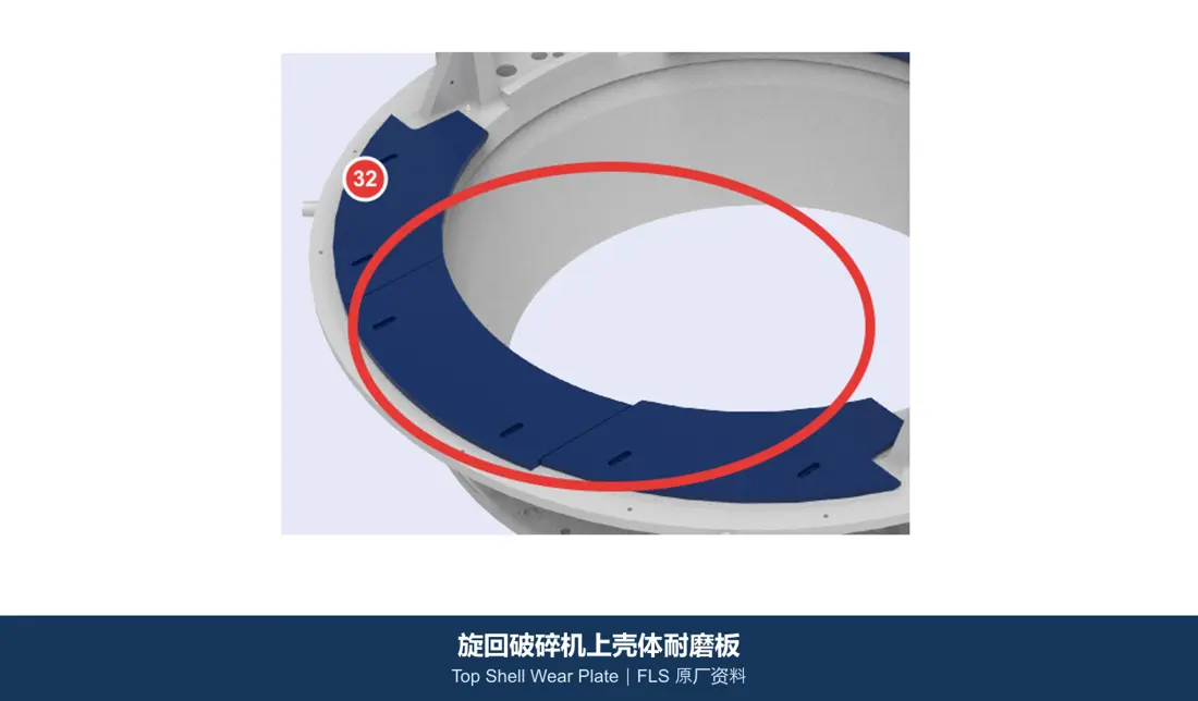
لوح تآكل الغلاف العلوي / منطقة التغذية
تحمي الغلاف العلوي والقادوس ومزلق التغذية المجاور. حددها بحسب نقطة السقوط وحجم الكتل ومناطق البطانات والثقوب والتراكبات وإتاحة الصيانة.
عرض صفحة الجزء المشترك →العمود الرئيسي والكم الواقي قطعتان منفصلتان. طابق العارضة ومجموعات العمود واللامركزية والتروس والجلب العلوية والضبط الهيدروليكي بحسب مواضع توصيلها وموادها الخاصة.
مجموعة العارضة
تحمل العارضة الدعم العلوي للعمود الرئيسي وتحدد ممرات التغذية. تختلف التصاميم الحلقية القياسية والحلقية المجزأة والعظمية والفكية في الهيكل والوزن والدعم وطريقة الفك؛ طابق الإصدار المركب.
عرض صفحة الجزء المشترك →مجموعة العمود الرئيسي
العمود الرئيسي هو العمود الحامل الكامل المنفصل عن كمه الواقي. تشمل المجموعة أيضا الرأس وصامولته وموضع اتصال محمل الارتكاز وطرف الدعم الهيدروليكي.
عرض صفحة الجزء المشترك →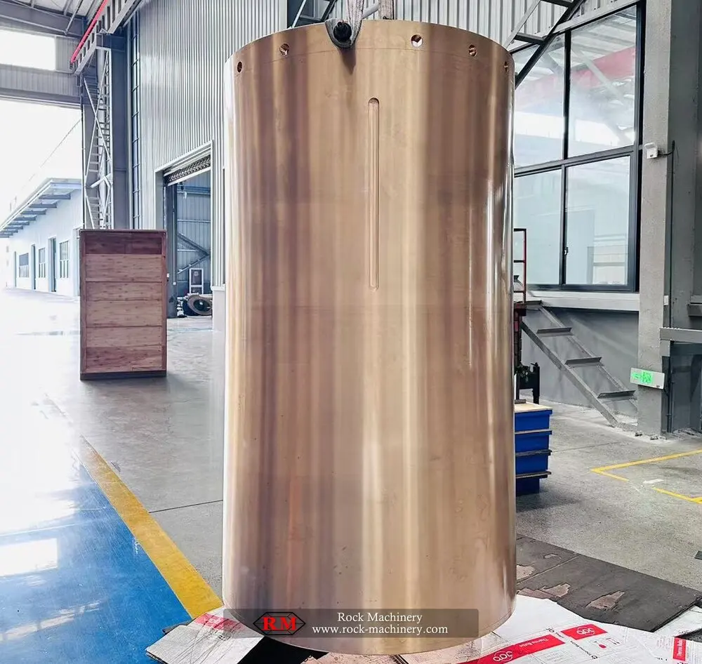
مجموعة اللامركزي & الجلبة
تحرك المجموعة اللامركزية العمود الرئيسي حركة دورانية متمايلة وتشمل الجسم والجلبة الداخلية والثقل الموازن والدعامات. طابق اللامركزية والأقطار ومجاري الزيت واتجاه الدوران وضبط الشوط بحسب الطراز.
عرض صفحة الجزء المشترك →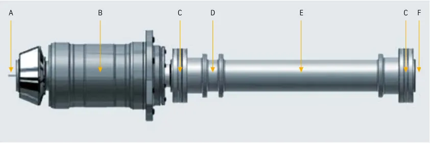
ترس مخروطي & ترس صغير (بينيون)
يستخدم المصنع الأصلي تعشيقا مخروطيا حلزونيا من نوع cyclo-palloid. طابق كزوج عدد الأسنان والموديول وزاوية الضغط واتجاه الحلزون وزاوية الأعمدة والخلوص الجانبي وعلامات المطابقة.
عرض صفحة الجزء المشترك →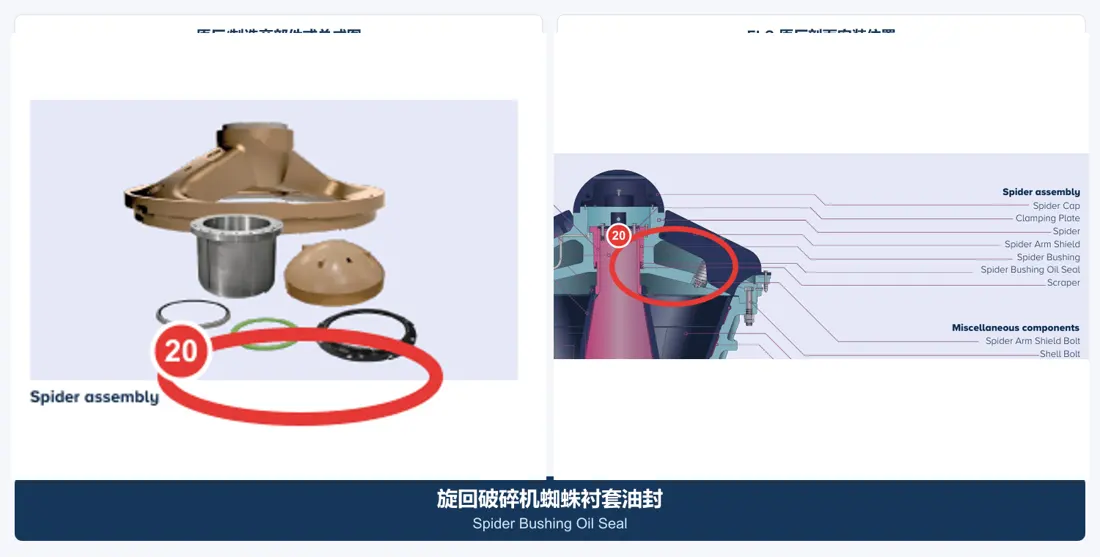
جلبة العارضة العلوية & ختم الزيت
تدعم حركة أعلى العمود الرئيسي في مركز العارضة. افحص التجويف والطول ومجاري الزيت والخلوص والتزييت واتجاه الختم مع عنق العمود.
عرض صفحة الجزء المشترك →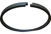
ضبط هيدروليكي & ختم المكبس
تدعم الأنظمة الهيدروليكية العمود الرئيسي وترفعه وتخفضه لضبط فجوة التفريغ وتعويض التآكل والحماية من الحمل الزائد. افحص معا قطر التجويف والشوط والضغط ومجاري الأختام وموضع اتصال محمل الارتكاز.
عرض صفحة الجزء المشترك →لا. تمتلك BK بنية فكية دوارة بفتحة موسعة من جانب واحد، لذلك تختلف عارضتها وغلافها وحجرتها ومنطقة تغذيتها عن KB. طابق الطراز الكامل والرقم التسلسلي والرسومات.
لا. العمود الرئيسي مطروقة داخلية كبيرة حاملة للأحمال؛ والكم قطعة واقية منفصلة تركب خارجه. تختلف المواد والأبعاد ومتطلبات التصنيع والقبول.
لا تتيح سجلات أغطية الأسنان الداخلية الحالية ربط الأرقام بمواضع KB / BK ومراجعات الرسومات بصورة موثوقة، لذلك لا تستنتج أرقام. ينشأ الربط بعد استلام اللوحة أو الرسم.
قدم الطراز وتجهيز Pro والرقم التسلسلي والفتحة وقطر المانتل والرسومات والصور والأبعاد والمواد وظروف الخدمة. ننسق التحديد وتقييم المادة والتصنيع ومراقبة الجودة والتسليم.
أو تواصل معنا مباشرة: +86 156 3797 3199
zzx@anranst.com
تقدّم ANRANST لعملائها حول العالم التقييم الهندسي والإنتاج في مسابك معتمدة وفق المتطلبات الفنية للعميل ومراقبة الجودة وتسليم القطع الجاهزة لقطع التآكل المخصّصة وقطع الغيار الصناعية، مع إمكانية دعم قطع صناعية مخصّصة أخرى.
نراجع أسطح التزاوج وأبعاد الوصلات، ونقيّم إمكانية التصنيع من حيث المادة والمعالجة الحرارية.
Material grades and heat-treatment processes are specified order by order, stated in the technical agreement and tracked through production.
تأكيد الرسم، ومراقبة المواد والعمليات، ومتابعة الإنتاج، والفحص، وتنسيق القبول.
ننسّق التصنيع وتأكيد الجودة والتغليف والتسليم للقطع الكاملة ضمن سلسلة توريد متكاملة وعملية.
زوّدنا بالطراز الحالي والرسومات والمواد أو ظروف التشغيل لنتمكن من تحديد المراجعة الفنية ومسار التوريد المناسبين.
أرسل استفساراً