thyssenkrupp ERC Eccentric Roll Crushers

Vision ERC History and current installation model, Key dimensions, wear parts and ordinary Drive spares Identification the Mining Division Product Range Now the FLS Acceptance.

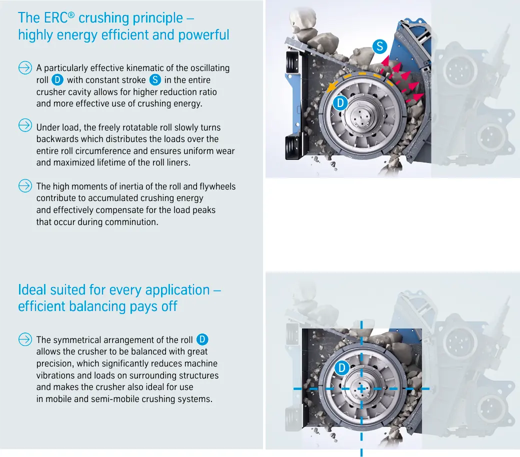
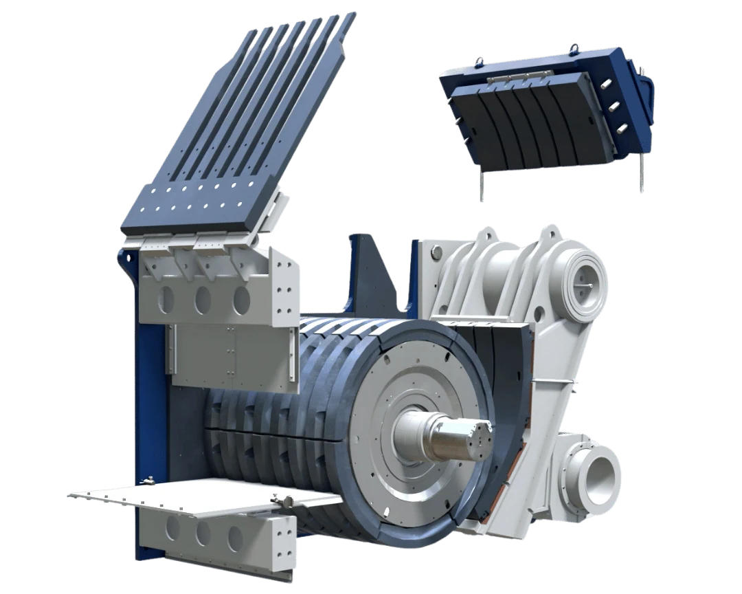
thyssenkrupp ERC Eccentric Roll Crushers Original factory sweep
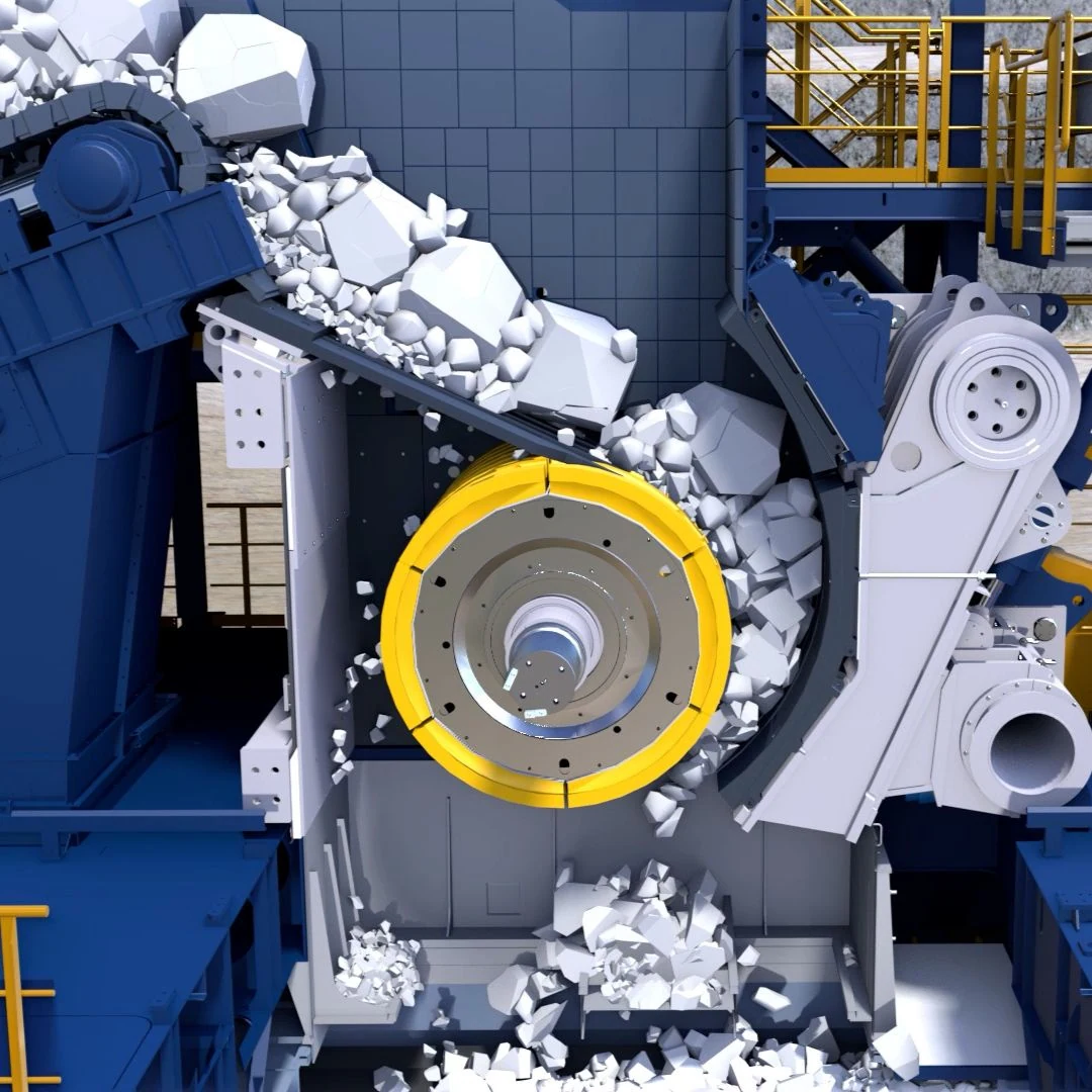
Original Factory ERC Whole machine Construction: Integrated Gessy, Centrifugal Broken Roller and Configuration jaw dies Hydraulic gaps and belt wheel drive.
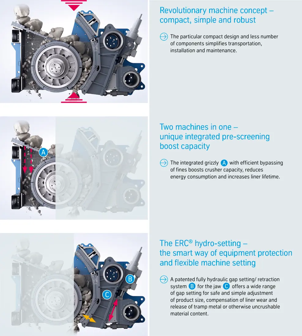
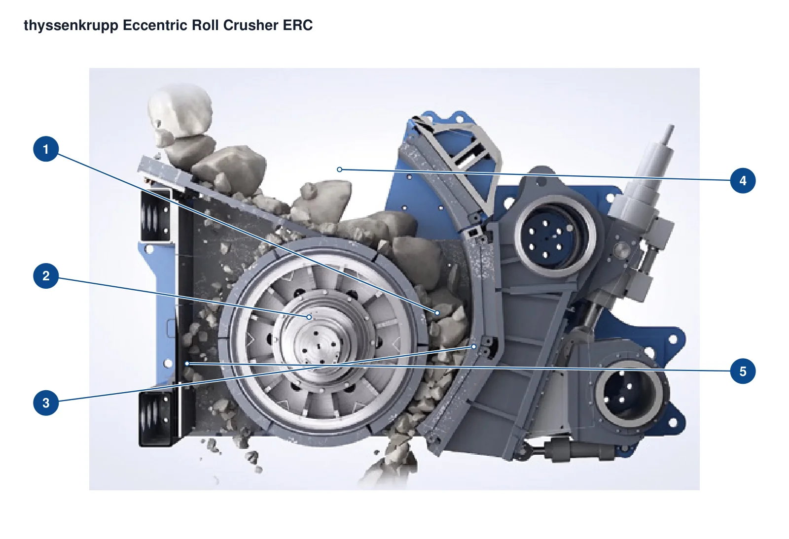
thyssenkrupp ERC Eccentric Roll Crushers Graphics of the cut
Original factory slicing diagram used Identification squid, crushed roller jaw dies Hydraulic bearings and drive positions.
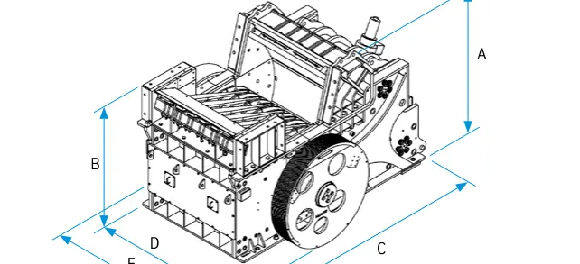
thyssenkrupp ERC Eccentric Roll Crushers Key dimensions Figures
Original Factory Key dimensions Definitions; specific A – E Values by ERC complete model Converging.
OEM Equipment Details

model smashing cavity parts and materials The path is concentrated on the same page.

The ERC combines static grille and primary crushing of the centrifugal rollers in a compact frame. This page retain only models, core sizes for spare parts identification requirements as well parts location to materials entry points or RFQ conditions without using project capability parameters like generic manufacturing specifications.

ERC 18-14–25-34 Original Factory Open Standard Models Scope
1800–2500 mm Open Roller Range
100–300 mm Public CSS Scope
2022 Mining Technologies Incorporation FLS
Standard Models and Key Dimensions

ERC Standard Models and spare parts Identification Dimensions

The following table uses the five standard configuration numbers in thyssenkrupp ERC' original manual. Processing volumes vary according to material characteristics, feed grade and CSS; Spare parts manufacturing is based on complete modeling (Series number) as well with drawings versions of this paper.

Standard ModelsRoller diameter / roll widthCore opening and discharge gapInstalled Power / Reference Weight
ERC 18-14Roller diameter 1800 mm / Roller width 1400 mmFeed Inlet 1000 mm; CSS 100 – 220 mm– kW - t (160; 300; 83)
ERC 22-20Roller diameter 2200 mm / Roller width 2000 mmFeed Inlet 1200 mm; CSS 120 – 260 mm– kW - t (300; 450; 138)
ERC 25-25Roller diameter 2500 mm / Roller width 2500 mmFeed Inlet 1280 mm; CSS 120 – 260 mm– kW - t (450; 600; 185)
ERC 25-30Roller diameter 2500 mm / Roller width 3000 mmFeed Inlet 1280 mm; CSS 140 – 300 mm– kW - t (500; 700; 215)
ERC 25-34Roller diameter 2500 mm / Roller width 3400 mmFeed Inlet 1280 mm; CSS 140 – 300 mm– kW - t (600; 800; 240)

The first set of the model corresponds to an approximated roller diameter, and a second sets correspond with its width; this rule is used only for initial identification that cannot replace nameplates or installers.

Wear Parts

smashing cavity wear parts, installation position and Materials

Roller linings, partitioning board and paired JAW DIES; stripes of the screen are identified by different impact locations as well. Card cards enter uniform parts & materials pages

Rolls of crush Liners / Broken parts Identification Figures
01

Rolls of crush Liners / Broken parts

Roll Liner / Crushing Element

The radial, wide rollers and plate segments of the strapping plates are installed outside a crushing roll with an opposite JAW die. Roll diameter is required to be confirmed by full ERC model as well in installation chart for rolling width;

Material Selection: First, high impact extrusion and abrasive operating conditions Screening high-manganese steel or Wear-Resistant Alloy Steel Specifics; materials, Hardness, heat treatment and NDT Originals and operating conditions OK, for sure.

View Part Details →
Broken Rolls Sharding Liners Identification Figures
02

Broken Rolls Sharding Liners

Roll Shell Segment

The sharding plate is arranged around the roll body, and it moves with a slow rotation to make wear spread along round circles. A set of blocks must be checked for number in pieces; perimeter positions are placed on each side as well AS holes connected by adjacent block interface or other parts that can also connect them together within one unit (or another).

Material Selection: Material System Needs to be met simultaneously Impact Toughness, Working surface Abrasion resistance and fixed zone strength; can be assessed as a whole alloy steel or local complex reinforcement program.

View Part Details →
Fixed Jaw Plates / Conversion jaw dies Identification Figures
03

Fixed Jaw Plates / Conversion jaw dies

Fixed Jaw / Counter Jaw

Located on the side of a crushed roller, it forms continuous fracture gap with an eccentric roll; its surface and thickness are associated to model & wear compensation positions.

Material Selection: Based on large blocks of hard rock impact, extrusion and sliding wear Assessment high-manganese steel or Wear-Resistant Alloy Steel, finally by drawing materials Performance and heat treatment Confirmation.

View Part Details →
Integrate sieve bar Identification Figures
04

Integrate sieve bar

Integrated Grizzly Bar

The static screen is located above the crushing cavity, allowing fine material to pass through.The gaps in a screening stripe and length of its installation direction must be confirmed by model or target feed level interface for replacement purposes

Material Selection: Working surface Touch and grinding, can be applied wear-resistant steel plate, alloy steel or local heaping reinforcement assessment; sieve and Construction The strength is prioritized by the original plot.

View Part Details →
smashing cavity side liners Identification Figures
05

smashing cavity side liners

Side Liner / Cheek Plate

Protection of the fractured cavity on both sides and Housing The adjacent area, side silhouettes and thicknesses of the head torso can not be replaced only by similar shapes.

Material Selection: Screening by side-facing extrusion, flies brush and edge wear wear-resistant steel plate or casting wear parts and the processing of welding restrictions.

View Part Details →
Injection and discharge area Liners Identification Figures
06

Injection and discharge area Liners

Feed / Discharge Area Liner

Covering the feed drop point, bypass channel and drain transition area. Combination of feeding direction / fall distances Liner hole pattern And downstream scooter Construction The subdivision is confirmed.

Material Selection: High impact zone and discharge sliding wear The same area should not be used by default materials.Evaluated separately by location wear-resistant steel plate, rubber Compound or local reinforcement.

View Part Details →
Spare Parts

eccentric shaft Hydraulics and General Drive spares

Power Transmission and the stubbornly unmixed Wear part. eccentric shaft, bearing, Shaft Sleeve Hydraulic gaps, belt wheels and flywheel respectively Interfaces Recognizes the payload.

eccentric shaft Total cum Identification Figures
01

eccentric shaft Total cum

Eccentric Shaft Assembly

The eccentric shaft drive crusher is a constant flow of the core transmission and force parts for ERC. Axle diameter, anxieties volume (Accuracy), couplings - bearing connections to endpoint must be confirmed in sets

Material Selection: Axle class materials, and the forging of heat treatment, mechanical properties and ultrasonic detection Quality The size tolerances must be reconciled according to the original figure and load.

View Part Details →
Roller Shaft Bearing and Shaft Sleeve Identification Figures
02

Roller Shaft Bearing and Shaft Sleeve

Roll Bearing & Bushing

The axis of the estral shaft with a rotating crushing roller is capable to withstand rail load, impact and low speed swing. Bearing model (slide), wheeled size or shape) must be confirmed by mounting record

Material Selection: Rolling bearing Template: Original model procurement; Shaft Sleeve or slid by the combination, load loading and temperature rise of copper alloying other original diagram provisions materials.

View Part Details →
Hydraulic gap and deductions Identification Figures
03

Hydraulic gap and deductions

Hydraulic Gap Setting & Retraction

For adjusting the gap of JAW dies, compensation for wear and deduction when unbreakables enter. The diameter is determined by model to be matched with a gauge in which it takes place; an ear shaft must also have been installed as well than sealed or pressure graded according models

Material Selection: hydraulic cylinder piston rods, pins The seal and the lanes are confirmed by drawings, pressure or environmental conditions respectively. They do not determine interchange with similar appearance

View Part Details →
Belt, flywheels and V Belts Power Transmission Identification Figures
04

Belt, flywheels and V Belts Power Transmission

Pulley, Flywheel & V-Belt Drive

Original Factory Construction Using motors, V Driven with and large inertial wheels. Wheel diameter, slot type Eccentric Bushing axis holes, keys and balance levels Protection Construction Installer must be installed Interfaces Confirmation.

Material Selection: General Power Transmission Fixed according to torque, fatigue and dynamic balance requirements Cast Steel, Ductile Iron or Alloy Steel Materials and Testing Item.

View Part Details →
jaw dies Continuation and connection Identification Figures
05

jaw dies Continuation and connection

Jaw Support & Connection Parts

Connectivity Fixed Jaw Plates Hydraulics and rack, affecting the discharge gap & concessional movement. pins, the earpieces Shaft Sleeve, fasteners Off and right Mounting Relationships must be combined.

Material Selection: The bearings and connector parts are selected by strength, shock fatigue punching shaft matchmaking process alloy steel or Construction Steel, key parts must be done on the map NDT.

View Part Details →

Only know ERC 25 - 30 Can the roller be directly determined Liners ?

No. Also confirm serial number, Rolling Shards and Fastening interface, jaw dies Configuration Conditioning of wear compensation, drawing number and Drawing Revision.

ERC Old nameplate Why are they linked at the same time? thyssenkrupp and FLS ?

ERC Origins from the original thyssenkrupp Mining Technologies Product Range the mining operations 2022 Year inbound FLS, Legacy Equipment Identification The current entrant relationship needs to be maintained simultaneously.

No OEM Part Number Can quotation ?

The identification can be based on complete model, serial number and installation diagrams; photos of used parts are available for measurement dimensions as well. Retraactive drawings must form before manufacturing with technical confirmation

Submission ERC complete model, nameplate, drawing number Or old ones

Provide ERC models, serial numbers CSS and plate segments drawing number photos of used parts sizes material materials as well operating conditions. We complete identifications for the purposes that we can identify them with our products; manufacture organizations to control quality in order they deliver finished-part items on this basis

Manufacturing Services in China

From Technical Assessment to Finished-Part Delivery

ANRANST provides customers worldwide with coordinated consulting, supplier sourcing, quality control and finished-part delivery for custom parts, wear parts and industrial spares from China, with scope to support other custom industrial parts.

01

Technical Advice

Equipment and part identification, drawing review, material selection and manufacturing feasibility assessment.

02

Supplier Introductions

Match requirements with suitable manufacturers in China and coordinate the exchange of technical information.

03

Quality Control

Drawing confirmation, material and process control, production tracking, inspection and acceptance coordination.

04

Finished-Part Delivery

Coordinate manufacturing, quality confirmation, packaging and delivery of complete finished parts.

Provide the existing model, drawings, drawing or part numbers, materials or operating conditions so we can identify the appropriate technical review and supply route.

Submit an Enquiry