HAZEMAG Impact Crushers

HPI, HPI-H, HSI, HTI, HPC Current Series and Legacy Installation entrance; model, the size of a rotor wear parts, Drive spares and materials The path is centralized check-up.

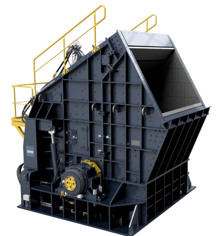
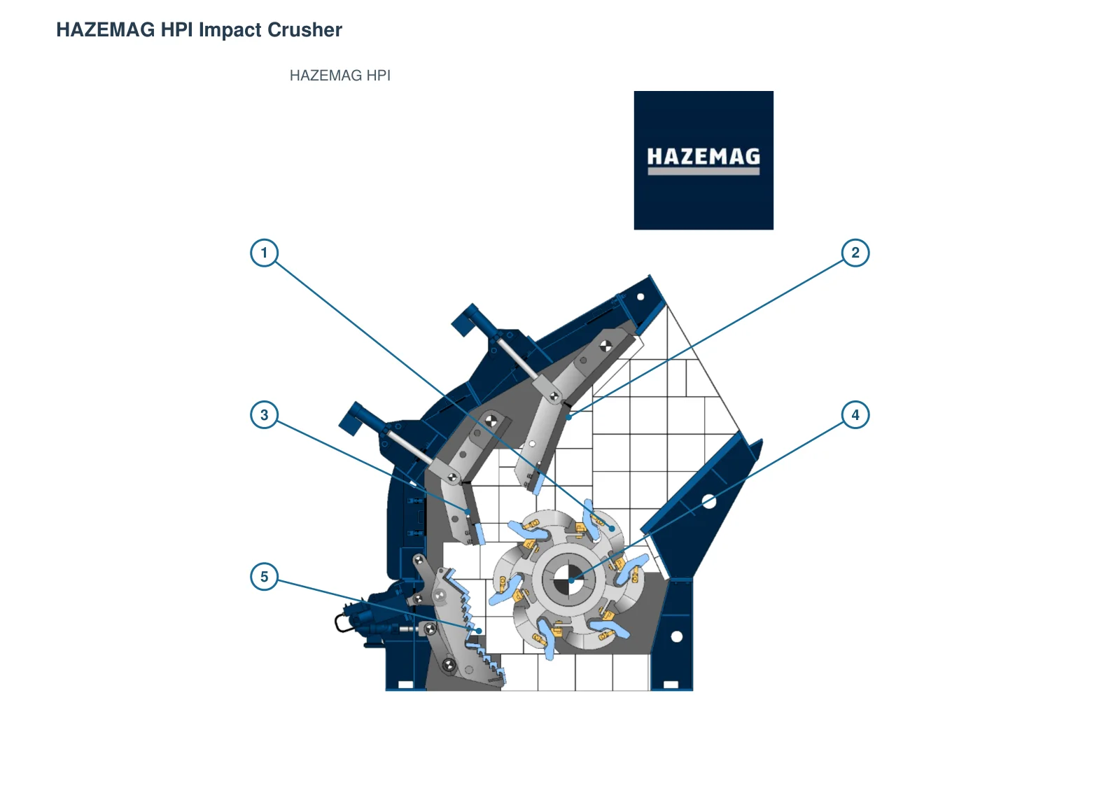
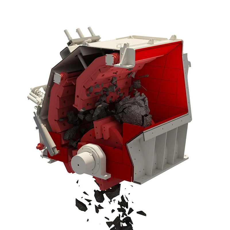
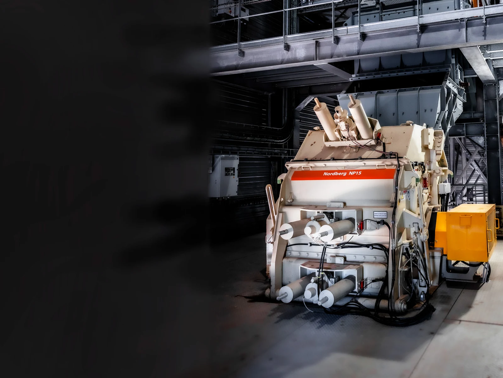
HAZEMAG HPI Primary Impact Crusher Official Product Picture
HAZEMAG HPI Primary Impact Crusher Official product charts; used Identification Large rotors, reciprocating barrel and crushing chamber Configuration.
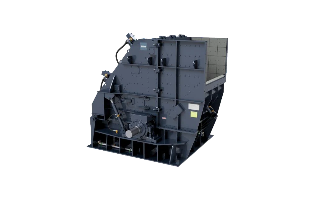
HAZEMAG HPI-H Primary Impact Crusher Official Product Picture
HAZEMAG HPI-H official product charts; GSK or QB Transponder and specific Configuration by complete model Confirmation.
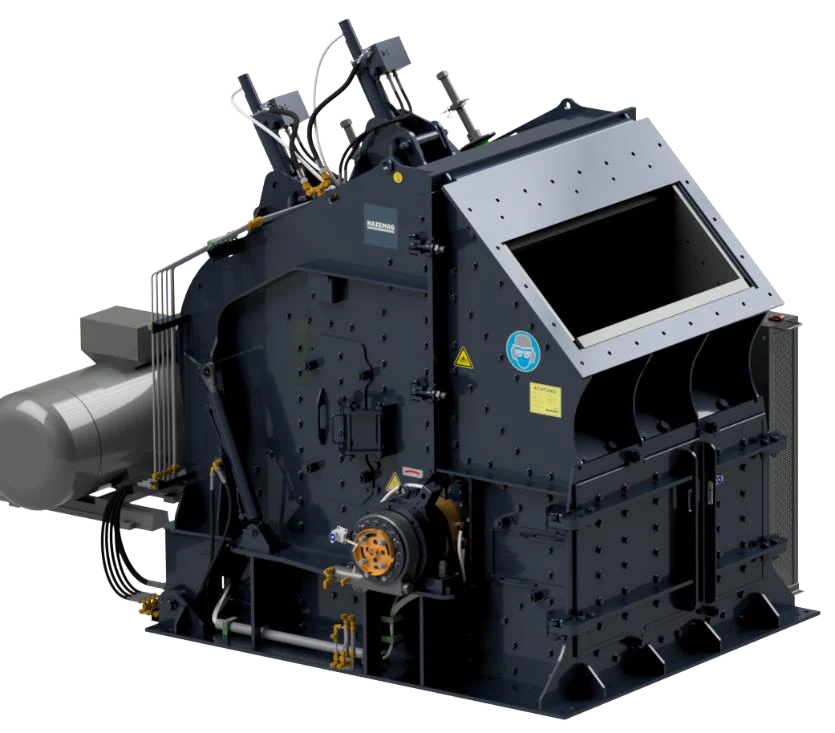
HAZEMAG HSI Secondary Impact Crusher Official Product Picture
HAZEMAG HSI Secondary Impact Crusher The official product chart; the rear-facing, Grinding Pathways and Rotatorwidths model Changes.
OEM Equipment Details

model, wear parts and Cores spare parts The same page closed loops

This page identifies and maps the Spare parts, retains only models of size HAZEMAG impact crusher installation confirmation that are directly related to model sizes or part locations. Final check-ups must be completed by nameplate (complete) Model(Series Number), General arrangement drawing/drawing number; Or traceable old items before manufacturing

5 Current Public Equipment Series
31 Current Published Models
5 History Series Group
12 wear parts and spare parts Category
Standard Models and Key Dimensions

HAZEMAG Impact Crusher Standard Series and Key dimensions

Tables below HAZEMAG Current Official HPI, HPI-H, HSI, HTI, HPC The product page is edited and retained with Current Series The name of the historical product as old Installation Identification Entrance.

Series and Standard ModelsOfficial capacity / Key dimensionsConstruction Scopespare parts Key checks
HPI:1622, 1822, 2022, 2025, 2030, 2225, 2230, 2530– t/h; the Transitional O × mm - August × mm (770; 2,500; 1,640; 2,250; 2,500; 3,000)Primary shocks are broken; can be pressed Configuration Belts Grinding Pathwaysmodel, the width of a rotor Blow Bar Forms, counter-attack and Grinding Pathways
HPI-H:1010, 1214, 1414, 1615, 1618– t/h; the Transitional O × mm - August × mm (165; 600; 1,030; 1,000; 1,640; 1,800)Primary shocks are broken; GSK or QB Rotary Configurationcomplete model Shifter, Transit Type, Blow Bar, counter-attack and hydraulic Configuration
HSI:1007, 1010, 1014, 1414, 1420, 1625, 1630– t/h; the Transitional O × mm - August × mm (40; 700; 1,030; 670; 1,540; 3,000)Secondary shocks are broken; front and rear repellent with optional Grinding Pathwaysthe width of a rotor, Breaker Plates Levels, Liner hole pattern and Reconciliating Agencies
HTI:1005, 1010, 101440 – 160 t/h; the Transitional O 1,010 × 500 / 1,000 / 1,340 mmVR2 / VR4 — / — -stage shock fractures; VR or VR Rotary ConfigurationRotary Configuration, Blow Bar Quantity, and the gaps in discharging Liners Location
HPC:1414, 1615, 1618, 1622, 1822, 2022, 2025, 2030-year round of the transient × mm - August × mm (1,340; 1,340; 2,000; 3,000)Double rotor composite crushing; two or three level repellent and Grinding PathwaysThe two-stage rotor position, rotational direction. Blow Bar, counter-attacks and Grinding Pathways
History Series: AP-PH / AP-PMH; AP-S / AP-SM / AP-SMH / AP-KH / AP-KMH; AP-VHM-R / AP-KVH-R; AP-CM / AP-CMHLegacy Installation Sizes with specific model Changes with YearReciprocate HPI-H, HSI, HTI and HPC Pre-Generation SeriesMust be united nameplate, serial number, general arrangement drawing, drawing number Verification of current and existing items

Processing capacity and rotor sizes are used for series start-ups, not representing the final manufacturing dimensions of specific devices. Old equipment must specifically match complete model serie number to draw numbers with drawings versions as well in handy items available on a scale that is set out below:

Wear Parts

smashing cavity wear parts, installation position and materials Pathways

Hazemag — The -class location organization by plate drum, countershell and grinding path; side wall. Official photos are used only for the corresponding products of HAZZEMAG: General graphics clearly identify in cards

HAZEMAG HMN Blow Bar Official Photos
01

Blow Bar System

Blow Bar System

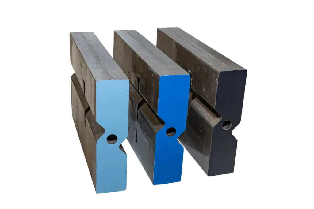
Hazemag — The hammer is the core parts of a rotor directly impacting material. HAZZEMAG officially publicizes three types: hMN, MMA and HSR; actual sectional pattern to be fixed as well AS assembly directions are still confirmed by both rotary models or original drawings

Material Selection: HMN Relatively to the manganese steel system, HMA Reciprocity Martensitic Steel system, HCR Reciprocity High-Chromium abrasion system; ceramic Or hardened phase augmentation only as a candidate for evidence.

View Part Details →
Impact Crushing -present rearrangement Liners Universal Locations Identification Figures
02

s and later Breaker Plates With the repellent Liners

Impact Apron Liner

Installing the front and rear counter-shell surface to withstand high speed material shock, sliding wear. Card chart is used for general location recognition without representing a geometry of one HAZEMAG model

Material Selection: Based on impact strength, abrasiveness and plate thicknesses Construction, from High-Chromium Wear-Resistant Materials, alloy steel or composite solution in the filter, finally by drawing and operating conditions Confirmation.

View Part Details →
Impact Crushing aircraft Grinding Pathways wear parts General Identification Figures
03

Grinding Pathways and Grinding Liang wear parts

Grinding Path Wear Parts

Location in the final fracture and outflow control area. Configuration, Number of beams and Liners Combination with HPI, HPI-H, HSI or HPC Specific Configuration Changes.

Material Selection: HAZEMAG Public Information Refers High-Chromium Steel Grinding The beam; the replacement also requires a check of cross-section, hole lineage and gaps. Construction.

View Part Details →
Impact Crushing aircraft side liners Universal Locations Identification Figures
04

side liners and Housing Protection boards

Side Liner & Housing Wear Plate

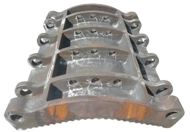
The smashing cavity side wall, rotor and shell grinding areas are protected. Card chart is a general structure recognition tool with actual outline of the shape to be determined by physical profile thicknesses or holes in line as well for parts that can fit into an installed drawing frame;

Material Selection: Often selected by the shock abrasion combination wear-resistant steel plate or casting Wear-Resistant Materials; different installation position It cannot be interchanged only by appearance.

View Part Details →
Impact Crushing aircraft Blow Bar Fixed wedge uniplex Identification Figures
05

Blow Bar Wedlock, scaffolding and fixed parts

Blow Bar Retention Parts

The hammer positioning, clamp and shock load transmission shall be carried out. A set of cuneiforms should also have been assembled to check the wedge boxes (cuplets), bearing bars or backboardes; a string for screwers as well in turnrs so that only one piece can not replace it with an assembly defection system

Material Selection: The fixed parts focus on strength, toughness and resilientity. heat treatment and size, not with Blow Bar Wear-Resistant Materials Simple equivalency.

View Part Details →
Impact Crushing aircraft Feed Inlet Liner Universal Locations Identification Figures
06

Feed Inlet With the crushing cavity entrance Liners

Feed Liner

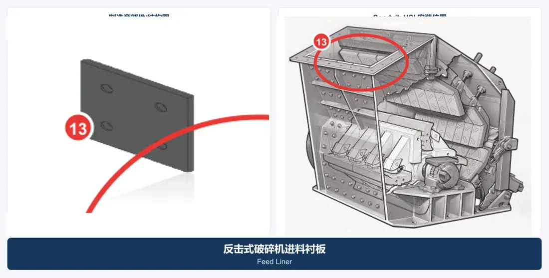
Located in the feed groove and crushing cavity entrance, it mainly withstands direct impact of large blocks material to damage or local deformation. Cardiographic maps are used only for general location Identification.

Material Selection: Material Options Depending on the particle size, defectiveness of feeds and jamsing cycle can be from high-manganese steel, wear-resistant steel plate or Composite liners Assessments in the middle.

View Part Details →
Spare Parts

rotors, axis systems and bearing-and hydraulic spare parts

General Power Transmission The scattering is separately listed. bearing, bearing housing, sealing and hydraulic cylinder and Impact Apron Assembly Installer must be installed Interfaces Check the Mating System.

HAZEMAG GSK Transit Official Construction Figures
01

GSK / QB Rotor Assemblies

Rotor Assembly

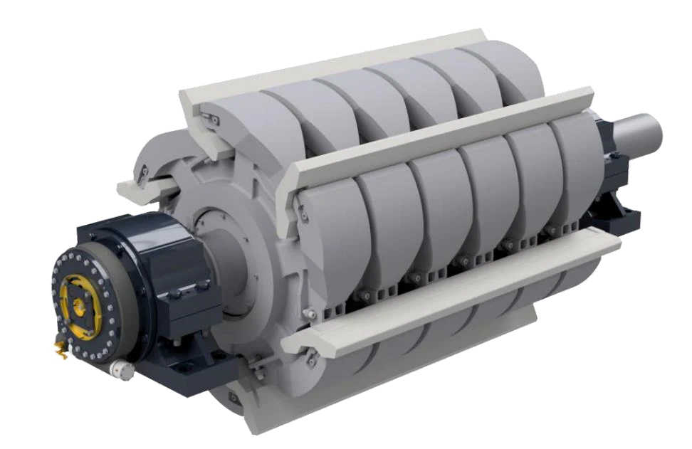
The rotor aggregate consists of the rotary body, plate hammer slots and axes as well.The structure in GSK'S series cannot be mixed with different equipment to match by complete model or rotational figure

Material Selection: Package Construction Key alignment of mother material, welding or casting routes heat treatment Dynamic Balance, NDT and the axis co-operation.

View Part Details →
Impact Crushing aircraft Rotor Shafts General Identification Figures
02

Rotor Shafts

Rotor Shaft

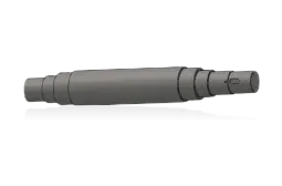
Transfer the drive torque and bear impact load. Converging axle, bearing Bits, sealing bitses or key groove Interfaces, rotational and dynamic balancing requirements.

Material Selection: Confirmed by the original diagram Forged Alloy Steel, heat treatment Mechanical performance, ultrasonic detection and key matching requirements.

View Part Details →
Impact Crushing aircraft bearing housing General Identification Figures
03

Rotor Bearing and bearing housing

Rotor Bearing & Bearing Housing

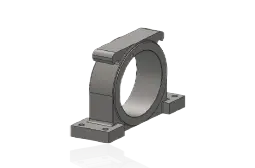
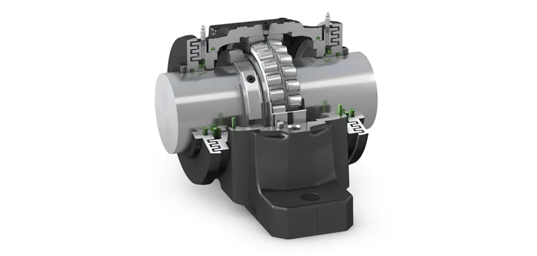
The scatter load the rotor and control its position. bearing model, swing space and pores; terminal cover. Luxor mode of navigation Interfaces -present Check the Mating System.

Material Selection: bearing by nameplate or IOM Recognizing; bearing housing Material, machining precision and NDT Requests to be executed on the drawing.

View Part Details →
Impact Crushing aircraft Rotor Bearing Seal General Identification Figures
04

Bearing Seals lubrication and Interfaces

Bearing Seal & Lubrication Interface

Protecting the dust and keeping it lucid. Construction lip direction, axle diameter. Refining Grooves, terminal cover and lube channels must be with bearing housing Together confirm.

Material Selection: Elastomers, engineering plastic and metals Seals Temperatures, dust and lubricants as well. Condition Selected.

View Part Details →
Impact Crushing Refractoral reversals hydraulic cylinder General Identification Figures
05

Refractoral adjustment hydraulic cylinder

Apron Adjustment Cylinder

Removal of the scaffolding and Overload Protection. Required Checks cylinder diameter, rod radius and stroke Mounting Ear shafts, oil groovees and working pressure Protection Configuration.

Material Selection: cylinders, pistons and rod Guiding The seal and the hydraulic parameters are confirmed by each of them, not only in shape.

View Part Details →
Impact Crushing aircraft Impact Apron Assembly General Identification Figures
06

Impact Apron Assembly, Pins and bushings

Impact Apron, Pin & Bushing

including counter-attack bearing Construction, the cranks. bushings and connectors. The total cube should be identified separately from the single part, rotation gaping position; Breaker Plates Interfaces and hydraulic connection.

Material Selection: mounts, pins and bushings materials and Surface treatment Each is different, and should be confirmed separately by loadings.

View Part Details →

Only know HPI or HSI Series Can the name be directly identified spare parts ?

No. At least the complete model, rotor size and serial number must be confirmed; rearranged or grinding path configurations are required to identify a drawing numbers as well for existing parts structures only in order narrowing check-out scope of this series name is needed at all times

HMN, HMA and HCR Blow Bar Can we exchange directly?

The material system cannot be interchangeable only by the name of materials. First, it must confirm plate hammer section size and length; slots are fixed in mode or rotor configuration before choosing a Material System according to impact & anterior operation conditions

Why this page is not unconfirmed OEM Part Number ?

HAZEMAG has a model, year and configuration difference with the series. No numbers supported by traceable directory or drawings are not published; nameplates can be submitted to make an additional check for old items as well

Submission HAZEMAG model, serial number, drawing number or old information

Provide complete model, serial number / rotor size and rearrange configurations for drawing numbers; photo-drawing of the available items (photograph), drawings or materials as well. We are able to identify material assessments in our products manufacturing organizations with quality control & finished parts delivery accordingly

Manufacturing Services in China

From Technical Assessment to Finished-Part Delivery

ANRANST provides customers worldwide with coordinated consulting, supplier sourcing, quality control and finished-part delivery for custom parts, wear parts and industrial spares from China, with scope to support other custom industrial parts.

01

Technical Advice

Equipment and part identification, drawing review, material selection and manufacturing feasibility assessment.

02

Supplier Introductions

Match requirements with suitable manufacturers in China and coordinate the exchange of technical information.

03

Quality Control

Drawing confirmation, material and process control, production tracking, inspection and acceptance coordination.

04

Finished-Part Delivery

Coordinate manufacturing, quality confirmation, packaging and delivery of complete finished parts.

Provide the existing model, drawings, drawing or part numbers, materials or operating conditions so we can identify the appropriate technical review and supply route.

Submit an Enquiry