HAZEMAG الكسارات الصدمية

Current HPI, HPI-H, HSI, HTI and HPC series and legacy installations: identify models, rotor dimensions, wear parts, drive spares and material options.

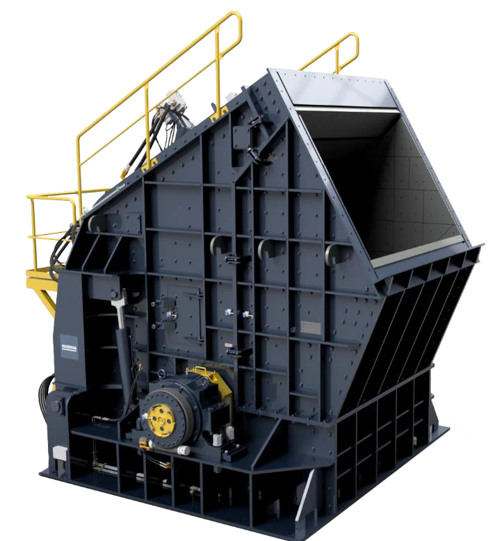
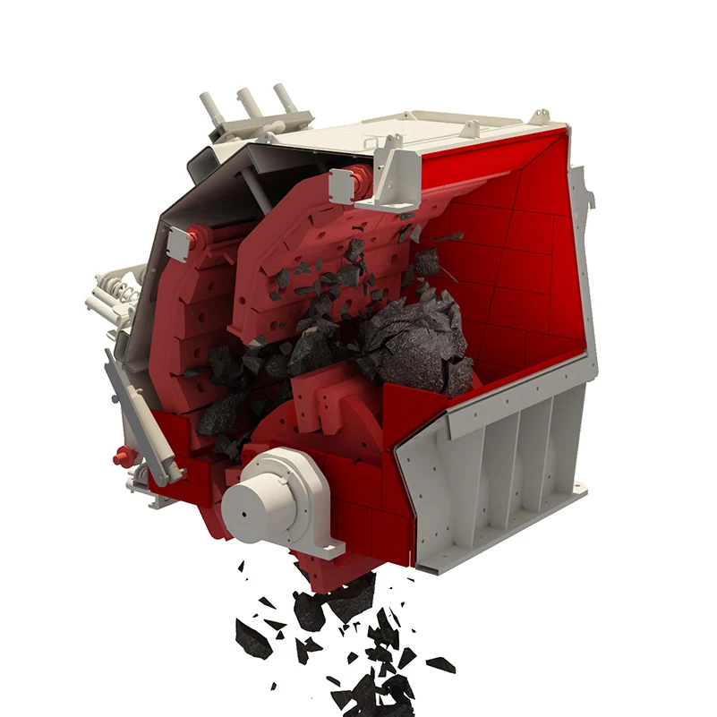
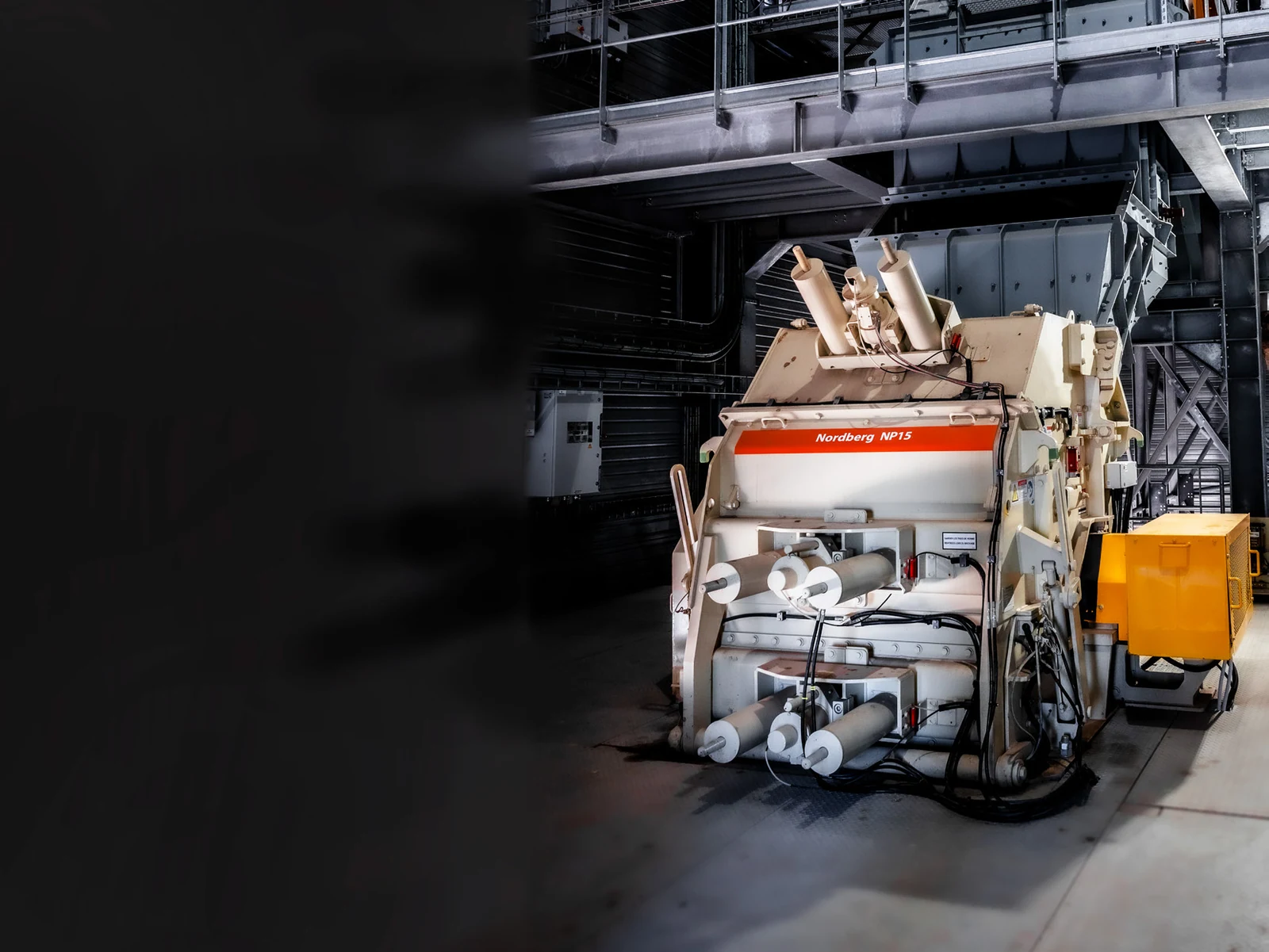
HAZEMAG HPI primary impact crusher, manufacturer image
Official HAZEMAG HPI primary impact crusher image, showing the large rotor, impact aprons and crushing chamber configuration.
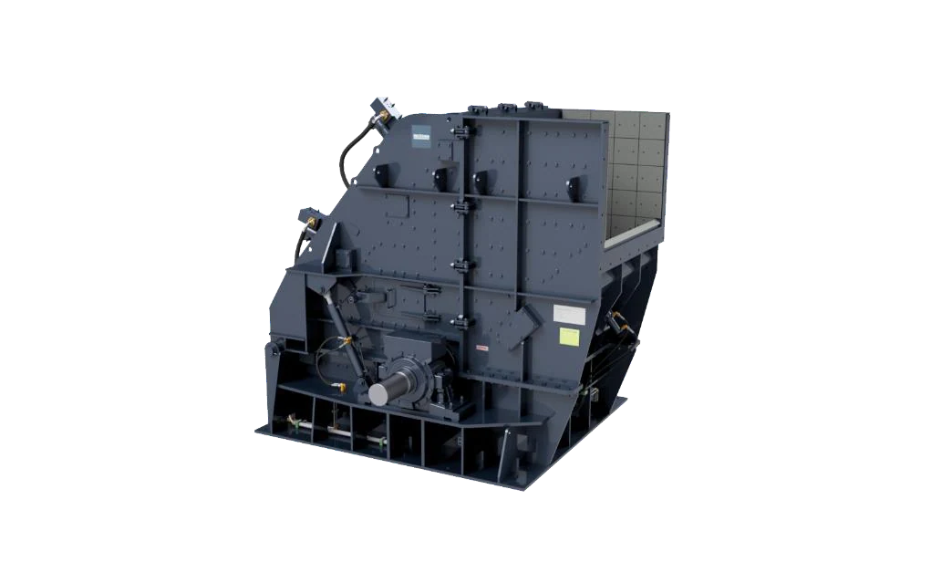
HAZEMAG HPI-H primary impact crusher, manufacturer image
Official HAZEMAG HPI-H image. Confirm the GSK or QB rotor and equipment configuration against the complete model designation.
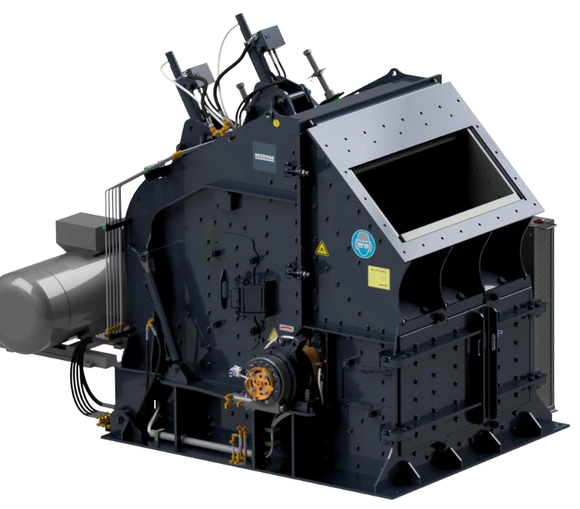
HAZEMAG HSI secondary impact crusher, manufacturer image
Official HAZEMAG HSI secondary impact crusher image. Front and rear impact aprons, grinding path and rotor width vary by model.
OEM المعدات Reference

Models, wear parts and core spare parts

Use this page to identify spare parts and prepare manufacture to drawing. It covers the models, dimensions, part locations, operating conditions and material options needed to identify a HAZEMAG impact crusher installation. Before manufacture, verify the nameplate, complete model, serial number, general arrangement drawing, drawing number or a traceable used part.

5 Current equipment series
31 Published current models
5 Legacy series groups
12 Wear-part and spare-part categories
Standard Models and Key Dimensions

HAZEMAG impact crusher series and key dimensions

The table follows HAZEMAG's current official HPI, HPI-H, HSI, HTI and HPC product pages. Predecessor product names are retained to help identify older installations.

Series and standard modelsPublished capacity / key dimensionsConfigurationKey spare-part checks
HPI: 1622, 1822, 2022, 2025, 2030, 2225, 2230, 2530770–2,500 t/h; rotor approximately Ø1,640 × 2,250 mm to Ø2,500 × 3,000 mmPrimary impact crushing; grinding path available according to configurationModel, rotor width, blow bar design, impact aprons and grinding path
HPI-H: 1010, 1214, 1414, 1615, 1618165–600 t/h; rotor approximately Ø1,030 × 1,000 mm to Ø1,640 × 1,800 mmPrimary impact crushing; GSK or QB rotor configurationComplete model, rotor type, blow bars, impact aprons and hydraulic configuration
HSI: 1007, 1010, 1014, 1414, 1420, 1625, 163040–700 t/h; rotor approximately Ø1,030 × 670 mm to Ø1,540 × 3,000 mmSecondary impact crushing; front and rear impact aprons with optional grinding pathRotor width, impact plate arrangement, liner hole pattern and adjustment mechanism
HTI: 1005, 1010, 101440–160 t/h; rotor approximately Ø1,010 × 500 / 1,000 / 1,340 mmTertiary impact crushing; VR2 or VR4 rotor configurationRotor configuration, blow bar quantity, discharge gap and liner position
HPC: 1414, 1615, 1618, 1622, 1822, 2022, 2025, 2030Rotor approximately Ø1,340 × 1,340 mm to Ø2,000 × 3,000 mmCompound crushing with two rotors; two or three impact apron stages and a grinding pathPosition of both rotors, direction of rotation, blow bars, impact aprons and grinding path
Legacy series: AP-PH / AP-PMH; AP-S / AP-SM / AP-SMH / AP-KH / AP-KMH; AP-VHM-R / AP-KVH-R; AP-CM / AP-CMHLegacy installation dimensions vary by model and yearPredecessor series of HPI-H, HSI, HTI and HPC respectivelyCross-check the nameplate, serial number, general arrangement drawing, drawing number and installed part

Capacity and rotor dimensions help narrow down the series; they are not final manufacturing dimensions for an individual machine. For older equipment, verify the complete model, serial number, drawing number, drawing revision and installed part.

قطع الغيار المستهلكة

Crushing chamber wear parts, installation positions and material options

Parts are organized into six areas: blow bars, impact aprons, grinding path, side walls, retention components and feed end. Official photographs apply only to the specified HAZEMAG products; generic illustrations are identified in the cards.

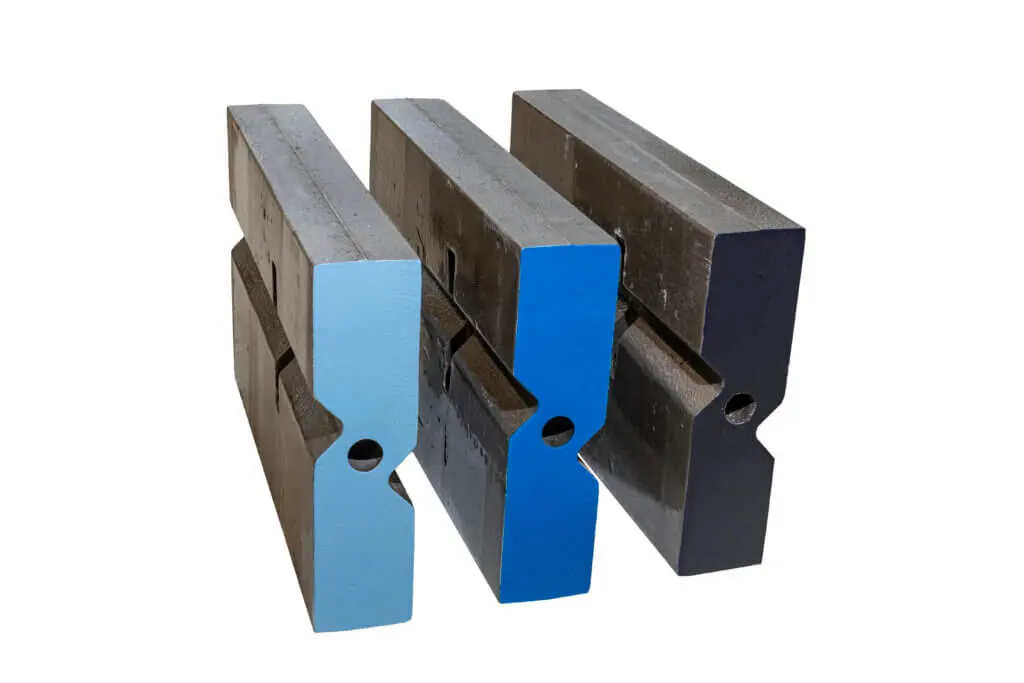
HAZEMAG HMN blow bar, manufacturer photograph
01

قضيب صدم للكسارة الصدمية System

قضيب صدم للكسارة الصدمية System

Blow bars are the rotor's main wear parts and strike the material directly. HAZEMAG publishes three blow bar systems: HMN, HMA and HCR. Confirm the cross-section, retention method and installation direction against the rotor model and original drawing.

Material selection: HMN denotes the manganese steel system, HMA the martensitic steel system and HCR the high-chromium wear-resistant system. Ceramic or hard-phase reinforcement is a candidate only where supported by evidence.

View the common part page →
Generic impact crusher apron liner, showing part location
02

Front and Rear Impact Plates and Apron Liners

Impact Apron Liner

Installed on the front and rear impact aprons, these liners withstand high-speed material impact and sliding wear. The illustration shows a typical part location, not the geometry of a particular HAZEMAG model.

Material selection: Screen high-chromium materials, alloy steels or composite options against impact severity, abrasiveness, plate thickness and attachment design. Confirm the final choice against the drawing and operating conditions.

View the common part page →
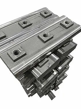
Generic grinding path wear parts for an impact crusher
03

Grinding Path and Grinding Beam قطع الغيار المستهلكة

Grinding Path قطع الغيار المستهلكة

These parts work in the final crushing and discharge-control area. The presence of a grinding path, number of beams and liner combination depend on the specific HPI, HPI-H, HSI or HPC configuration.

Material selection: HAZEMAG's public information refers to high-chromium steel grinding beams. Replacement parts also require checks of the cross-section, hole pattern, gaps and support structure.

View the common part page →
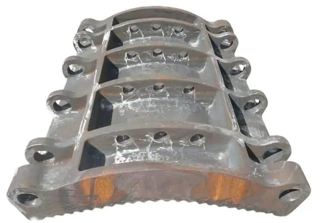
Generic impact crusher side liner, showing part location
04

البطانة الجانبية and Housing Protection Plates

Side Liner & Housing Wear Plate

Protect the crushing chamber side walls, both sides of the rotor and wear-prone housing areas. The illustration shows a generic structure; the actual profile, thickness, hole pattern and segmentation must follow the installation drawings.

Material selection: Wear-resistant plate or cast wear-resistant materials are commonly selected according to the combination of impact and abrasion. Similar appearance does not make parts from different installation positions interchangeable.

View the common part page →
Generic impact crusher blow bar retention wedge
05

قضيب صدم للكسارة الصدمية Wedges, Support Bars and Retention Parts

قضيب صدم للكسارة الصدمية Retention Parts

These components locate and clamp the blow bars and transfer impact loads. Check wedges, support bars, backing plates, bolts and rotor slots as a set; replacing one component without checking its mating parts may cause assembly mismatch.

Material selection: Retention parts require strength, toughness, suitable heat treatment and accurate fits. Their material requirements are not the same as those of the wear-resistant blow bar.

View the common part page →
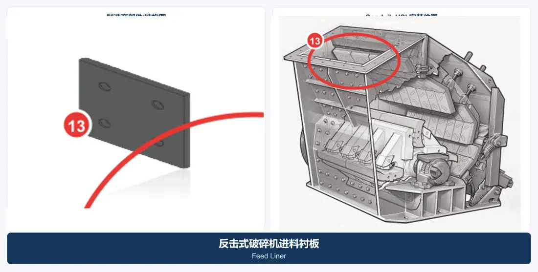
Generic impact crusher feed liner, showing part location
06

Feed Inlet and Crushing Chamber Entrance Liners

Feed Liner

Located in the feed chute and chamber entrance, these liners mainly withstand direct impact from large lumps, scoring and local deformation. The illustration is for generic location identification only.

Material selection: Material options depend on feed size, drop height, contaminants and maintenance intervals. High-manganese steel, wear-resistant plate or composite liners may be assessed.

View the common part page →
قطع الغيار

Rotor, shaft, support and hydraulic spare parts

Drive and support components are listed separately. Check the rotor, shaft, bearings, bearing housings, seals, hydraulic cylinders and impact apron assemblies together against the installed machine's interfaces.

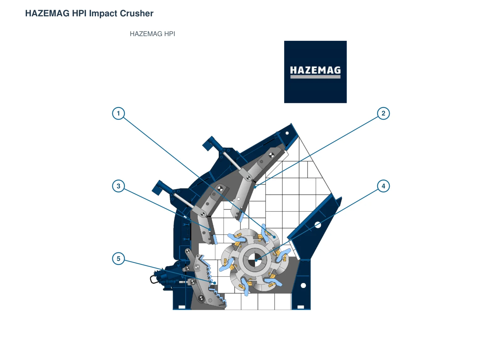
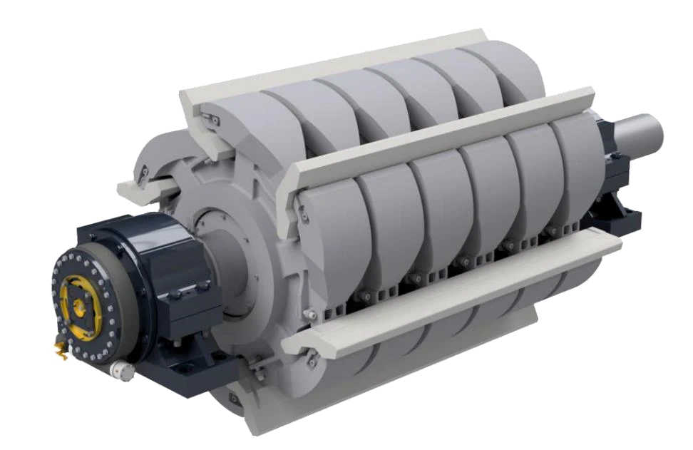
HAZEMAG GSK rotor, manufacturer diagram
01

GSK / QB Rotor Assembly

Rotor Assembly

The assembly comprises the rotor body, blow bar slots, shaft and retention components. GSK, QB and rotors from different equipment series must not be mixed; verify the complete model and rotor drawing.

Material selection: For the load-bearing structure, check the base material, welded or cast construction, heat treatment, dynamic balance, nondestructive testing and shaft fits.

View the common part page →
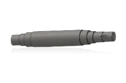
Generic impact crusher rotor shaft
02

Rotor Shaft

Rotor Shaft

Transmits drive torque and withstands impact loads. Check shaft ends, bearing and seal seats, keyways or locking assembly interfaces, rotation direction and dynamic balancing requirements.

Material selection: Confirm the forged alloy steel, heat treatment, mechanical properties, ultrasonic testing and critical fit requirements against the original drawing.

View the common part page →
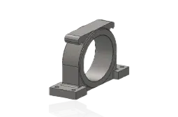
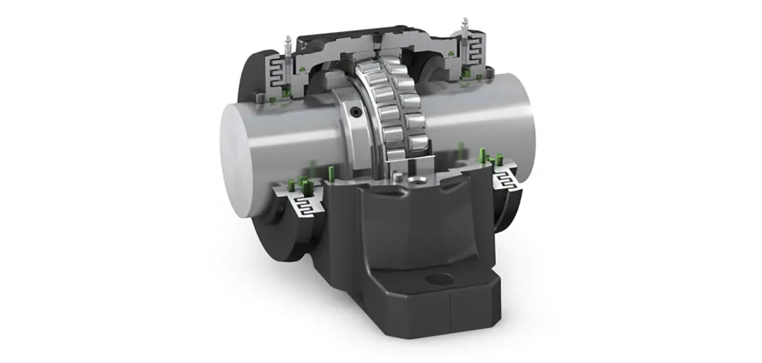
Generic impact crusher bearing housing
03

Rotor المحامل ومبيتات المحامل

محامل الدوار & غلاف المحمل

Support the high-speed, heavily loaded rotor and maintain shaft position. Check bearing designation, clearance, housing bore, end covers, lubrication method and temperature-monitoring interfaces as a set.

Material selection: Identify bearings from their markings or the IOM. Housing material, machining accuracy and inspection requirements must follow the drawing.

View the common part page →
Generic impact crusher rotor bearing seal
04

موانع المحامل and Lubrication Interfaces

Bearing Seal & Lubrication Interface

Exclude dust and retain lubricant. Check the seal design, lip direction, shaft diameter, grooves, end covers and lubrication passages together with the bearing housing.

Material selection: Select elastomers, engineering plastics and metal seals according to temperature, dust, lubricant and shaft surface condition.

View the common part page →
Generic impact crusher apron adjustment cylinder
05

Impact أسطوانة هيدروليكية لضبط حاجز الصدم

أسطوانة هيدروليكية لضبط حاجز الصدم

Adjusts the impact apron gap and provides overload protection. Check cylinder bore, rod diameter, stroke, mounting trunnions, ports, working pressure and protective features.

Material selection: Confirm the cylinder tube, piston rod, guides and seals separately against hydraulic parameters and the original drawing. Appearance alone is not a basis for replacement.

View the common part page →
Generic impact crusher impact apron assembly
06

مجموعة حاجز الصدم, Pins and Bushings

Impact Apron, Pin & Bushing

Includes the apron support structure, pivots, bushings and connections. For assemblies and individual parts, confirm position, rotational clearance, lubrication, impact plate interfaces and hydraulic connections separately.

Material selection: The support frame, pins and bushings require different materials and surface treatments. Confirm each according to loads, fits and maintenance methods.

View the common part page →

Is the HPI or HSI series name enough to identify a spare part?

No. Confirm the complete model, rotor dimensions, serial number, impact apron or grinding path configuration, drawing number and installed part design. The series name only narrows the search.

Are HMN, HMA and HCR blow bars interchangeable?

Material names alone do not establish interchangeability. First confirm the blow bar cross-section, length, slots, retention method and rotor configuration; then select the material system for the impact and abrasion conditions.

Why are unconfirmed OEM part numbers omitted?

Models, years and configurations differ even within one HAZEMAG series. We do not publish numbers without a traceable catalogue, drawing or installation record. Submit a nameplate, drawing number or used part for further checking.

Submit Your HAZEMAG Model, Serial Number, Drawing Number or Used-Part التفاصيل

Provide the complete model, serial number, rotor dimensions, impact apron configuration, drawing number, installed-part photographs, drawings, material and operating conditions. We use these to identify the part, assess materials, organize manufacture, coordinate quality control and deliver the finished item.

Submit التفاصيل for a Quote

رقم الهاتف: +86 156 3797 3199
zzx@anranst.com

خدمات صنع في الصين

من التقييم الفني إلى تسليم المنتج بالكامل

توفر شركة ANRANST للعملاء العالميين تقييمات هندسية، واختيار التصنيع الصيني، ومراقبة الجودة، وتسليم الأجزاء النهائية لقطع الغيار الصناعية المقاومة للتآكل حسب الطلب، ويمكنها أيضًا دعم قطع الغيار الصناعية الأخرى حسب الطلب.

01

مراجعة الرسومات والهندسة

قم بمراجعة أسطح التزاوج وأبعاد الواجهة، وقم بتقييم جدوى المواد والمعالجة الحرارية والتصنيع.

02

تحديد المادة والمعالجة الحرارية

تُحدَّد درجات المواد وعمليات المعالجة الحرارية لكل طلب على حدة، وتُثبَّت في الاتفاقية الفنية وتُتابَع أثناء الإنتاج.

03

ضبط الجودة

يشمل ذلك تأكيد الرسم، ومراقبة المواد والعمليات، وتتبع الإنتاج، وتنسيق عمليات الفحص والقبول.

04

تسليم المنتج النهائي

تنظيم عمليات التصنيع والتحقق من الجودة والتعبئة والتغليف وتسليم المنتجات النهائية الكاملة لتشكيل حلقة إمداد قابلة للتنفيذ.

قم بتزويدنا بالنماذج الحالية، والرسومات، وأرقام الرسومات، وأرقام الأجزاء، والمواد، أو معلومات ظروف التشغيل، وسنقوم بتحديد التحقق الفني ومسار التوريد وفقًا لذلك.

إرسال طلب