HAZEMAG كسارات التحجيم المعدنية HCS/HSS

Primary HCS, secondary HCS and HSS side sizers: standard models, throughput, center distance, roll length, crushing caps and segments, shafts and drive spares.

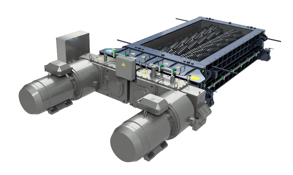
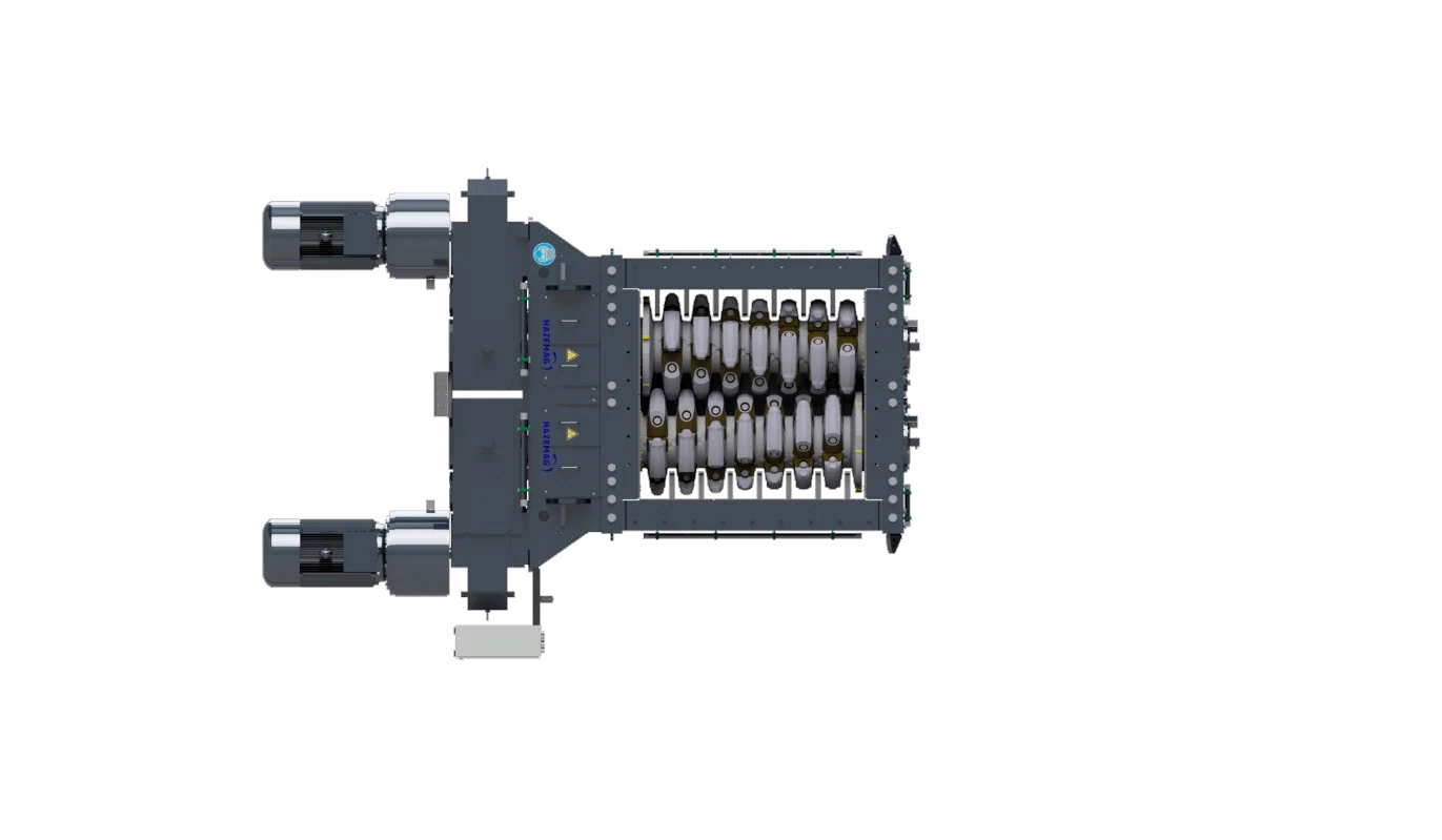
HAZEMAG HCS الكسارة المسننة المركزية, manufacturer photograph
Manufacturer photograph of a HAZEMAG HCS الكسارة المسننة المركزية, showing both rolls, housing, crushing caps and end supports.
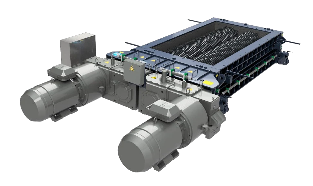
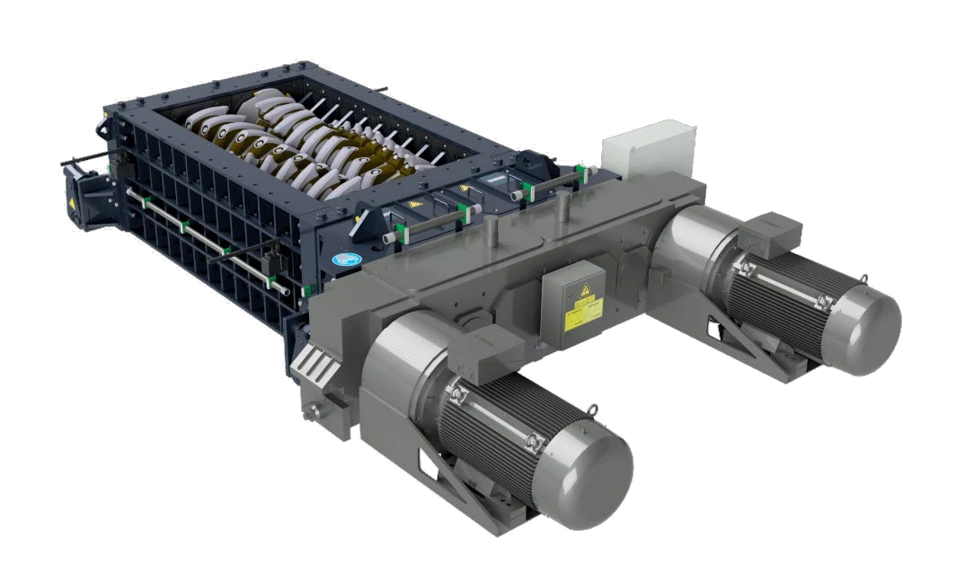
HAZEMAG HCS الكسارة المسننة المركزية, manufacturer image
Manufacturer image of an HCS الكسارة المسننة المركزية. Confirm center distance, roll length and tooth profile against the standard model and project configuration.
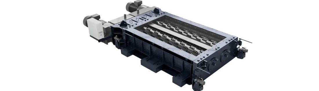
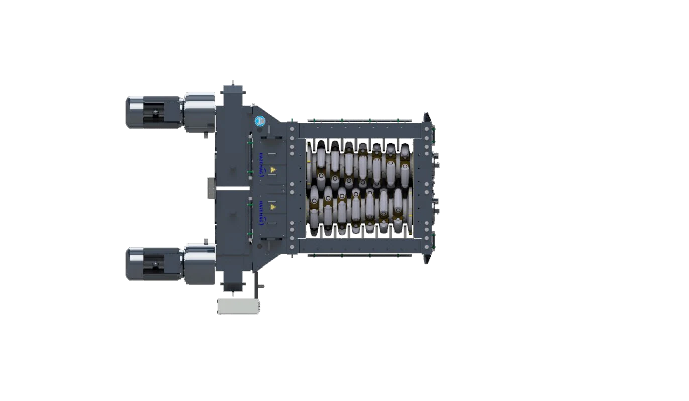
HAZEMAG HSS Side Sizer, manufacturer image
Manufacturer image of an HSS Side Sizer. Each roll turns toward its respective side wall; its side crushing zones differ from the HCS arrangement.
OEM المعدات Reference

40 manufacturer-listed models, wear parts and drive spares

This page lists models and dimensions directly relevant to HAZEMAG HCS/HSS installation identification, wear parts and core spares. Center distance and roll length narrow the series. Before manufacture, confirm tooth profile, rotation direction, retention and drive interfaces using the nameplate, complete model, serial number, general arrangement, drawing number or traceable used part.

15 Primary HCS models
14 Secondary HCS models
11 HSS models
40 Current published standard models
Standard Models and Key Dimensions

HAZEMAG HCS/HSS standard models and key dimensions

Models follow HAZEMAG's current official technical data for primary HCS, secondary HCS and HSS. Four key parameters are retained for spare-part identification: throughput, maximum feed size, center distance and roll length.

Series and standard modelsThroughput / maximum feed sizeCenter distance / roll lengthKey spare-part checks
Primary HCS 06: 0610, 0616, 0620, 0625650–1,650 t/h; maximum feed size 1,000 mmCenter distance 680 mm; roll length 970–2,475 mmCrushing caps, crushing rings, shafts, breaker bar and drive interfaces
Primary HCS 08: 0816, 0820, 0825, 08301,350–2,500 t/h; maximum feed size 1,200 mmCenter distance 850 mm; roll length 1,690–2,990 mmCap arrangement, roll length, housing liners and drive configuration
Primary HCS 10/13: 1020, 1025, 1030, 1040; 1320, 1330, 13402,100–5,300 t/h; maximum feed size 1,500 / 2,000 mmCenter distance 1,050 / 1,350 mm; roll length 1,925–4,120 mmLarge shafts, crushing rings, caps, bearing housings and gearbox interfaces
Secondary HCS 05/06: 0510, 0516, 0520; 0610, 0616, 0620, 0625, 0630290–1,200 t/h; maximum feed size 250 / 350 mmCenter distance 550 / 680 mm; roll length 1,020–3,060 mmReplaceable segments, clearances, breaker bar and front / rear wall protection
Secondary HCS 08: 0810, 0816, 0820, 0825, 0830, 0840500–2,050 t/h; maximum feed size 450 mmCenter distance 850 mm; roll length 1,020–4,080 mmSegment combinations, long roll shafts, liners and drive assemblies
HSS 06: 0610, 0616, 0620, 0625, 0630550–1,650 t/h; maximum feed size 250 mmCenter distance 680 mm; published roll length approximately 1,020–3,060 mmOutward-turning rolls, side crushing zones and hydraulically adjustable walls
HSS 08: 0810, 0816, 0820, 0825, 0830, 0840900–3,500 t/h; maximum feed size 350 mmCenter distance 850 mm; published roll length approximately 1,020–4,080 mmSegments, side liners, shafts, adjustment mechanisms and drive interfaces

Published capacities and dimensions support initial model identification. Parts within one model can differ with material, tooth profile, roll length, drive and project configuration. The technical table is not a manufacturing drawing.

قطع الغيار المستهلكة

Crushing teeth, housing protection and material options

Parts are grouped by the actual HCS/HSS structure: crushing caps, replaceable segments, roll shells, breaker bars or side walls, housing liners and retention parts. Material options support preliminary screening; the original drawing and inspection requirements govern the final specification.

HAZEMAG HCS crushing rolls and caps, manufacturer top view
01

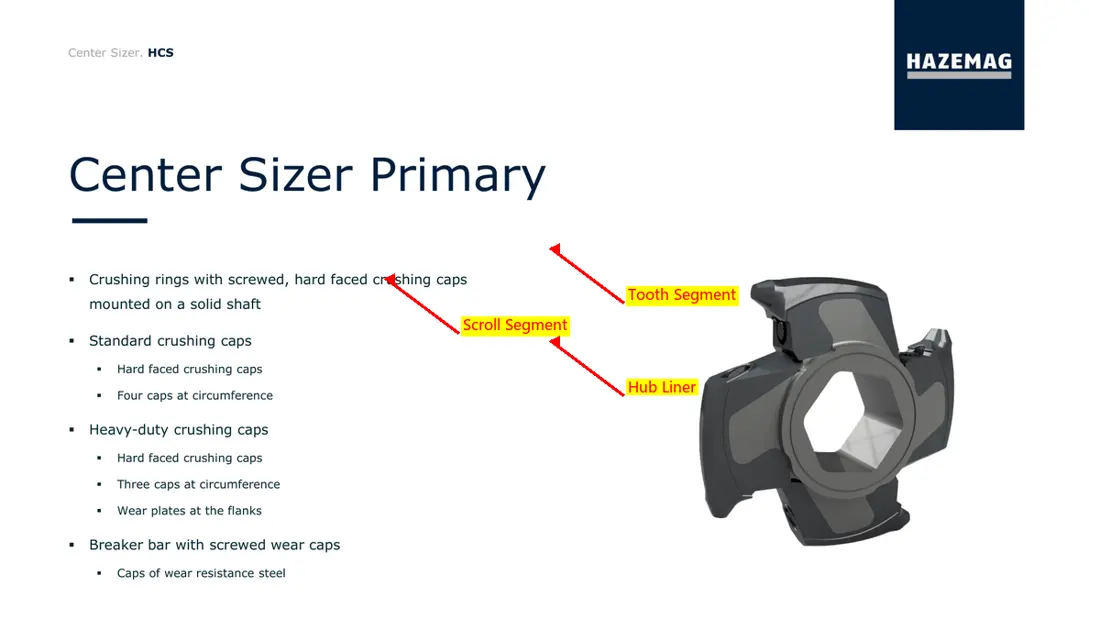
Crushing Caps and Crushing Rings

Crushing Cap & Crushing Ring

Primary HCS and some secondary configurations use replaceable caps mounted on crushing rings. Check the series, center distance, roll length, cap position, tooth profile, rotation direction and retention structure.

Material selection: The public manufacturer page does not prescribe one material grade. Screen tough alloy steels, manganese steels or composite wear-resistant options against impact, abrasion, stickiness and the original drawing.

View the common part page →
HAZEMAG HCS replaceable crushing segments, manufacturer image
02

Replaceable Crushing Segments

Replaceable Crushing Segment

Secondary or tertiary HCS crushing shafts may use replaceable segments. Appearance alone is insufficient: check shaft position, angle, tooth count, segmentation, retention method and assembly clearances.

Material selection: Confirm material and heat treatment against tooth-root impact, tip wear, cross-section and the original drawing. Surface reinforcement or hardfacing requires a suitable structure and an established process.

View the common part page →
HAZEMAG HSS crushing roll section, manufacturer image
03

Roll Shells, Shaft Sleeves and Segment Carriers

Roll Shell & Segment Carrier

These structures mount the caps or segments and transfer loads. Check outside diameter, axial length, segment interfaces, keys or splines, fastening holes and dynamic balancing requirements.

Material selection: Confirm the base material, forging or casting route, heat treatment, welding restrictions and nondestructive testing against the complete drawings.

View the common part page →
HAZEMAG HSS side crushing zone, manufacturer image
04

Breaker Bars, Side Walls and Gap-Control قطع الغيار المستهلكة

Breaker Bar & Crushing Wall قطع الغيار المستهلكة

HCS controls product size through the breaker bar and roll gap. HSS crushes between each roll and its side wall. Wear-part positions and profiles from these two structures must not be mixed.

Material selection: Screen wear-resistant plate, alloy steel or composite liners according to direct impact, compression and sliding wear. Check support stiffness and attachment design as well.

View the common part page →
HAZEMAG HCS housing and bearing-end protection area, manufacturer image
05

Front, Rear and Side Wall Liners and Bearing Protection

Housing & Bearing Protection Liner

Protect the front and rear housing walls, side walls, discharge end and areas near bearings. Segmentation, thickness, holes and installation sequence vary with HCS/HSS model and configuration.

Material selection: Select wear-resistant plate or cast wear parts according to abrasion, impact, deformation risk and handling weight. Confirm against drawings and the installed part.

View the common part page →
HAZEMAG HCS segment retention area, manufacturer image
06

Segment Bolts and Retention Parts

Segment Bolt & Retention Parts

Retention parts withstand clamping, alternating impact and vibration. Identify threads, heads, strength grades, preload requirements, locking features and matching washers as a complete set.

Material selection: Confirm the high-strength alloy steel grade, heat treatment, mechanical properties, surface protection and assembly preload against the original drawing.

View the common part page →
قطع الغيار

Shafts, supports, drives and adjustment mechanisms

Drive components are listed separately. Crushing roll shafts, bearing housings, gearboxes, fluid couplings, mechanical couplings and adjustment mechanisms must be checked against the complete installation interfaces.

HAZEMAG HCS twin crushing roll shafts, manufacturer top view
01

Crushing Roll Shaft Assembly

Crushing Roll Shaft Assembly

Includes the shaft, cap or segment mounting areas, end connections and support interfaces. Identify the HCS/HSS series, center distance, roll length, shaft position and rotation direction separately.

Material selection: Confirm forged alloy steel, heat treatment, flaw detection, dimensional tolerances and critical fits against shaft drawings and load conditions.

View the common part page →
HAZEMAG HCS bearing end and drive side, manufacturer image
02

Bearings, Housings and End الموانع

Bearing, Housing & End Seal

Carry radial and axial loads from low-speed, high-torque roll shafts. Check bearing designation, clearance, housing bore, covers, seals and lubrication interfaces as a complete bearing-end assembly.

Material selection: Identify bearings from markings or maintenance information. Check housings, covers and seals separately against drawings, machining accuracy, temperature and dust conditions.

View the common part page →
Generic mineral sizer gearbox and drive assembly
03

علبة التروس and Drive Assembly

علبة التروس & Drive Assembly

HAZEMAG describes a motor, fluid coupling, gearbox and mechanical coupling from gearbox to rotor. The illustration identifies a generic drive arrangement; it does not establish interchangeability between particular models.

Material selection: For gears, shafts, housings and connections, check ratio, torque, rotation direction, mounting orientation, tooth heat treatment, accuracy and lubrication separately.

View the common part page →
HAZEMAG HCS drive side, manufacturer image
04

Fluid Coupling

Fluid Coupling

Provides heavy-load starting and overload protection. Confirm the complete coupling model, fill requirements, rated power and speed, input and output interfaces, mounting orientation and protective features.

Material selection: Select the assembly from its nameplate, drive parameters and interface dimensions. Seal materials also require temperature and working-fluid checks.

View the common part page →
HAZEMAG HSS drive and coupling area, manufacturer image
05

Mechanical Couplings and Connections

Mechanical Coupling & Connection Parts

Connect the gearbox and crushing roll, transmitting high torque at low speed while accommodating specified installation deviations. Check connection type, bore, keys or splines, bolt circle and guards.

Material selection: Confirm couplings and high-strength connections against torque, impact, fatigue, fits and heat treatment requirements.

View the common part page →
HAZEMAG HSS side-wall gap adjustment structure, manufacturer image
06

Gap Adjustment Parts and Mechanisms

Gap Adjustment Parts

The HCS roll or breaker-bar gap and the HSS side-wall gap use different adjustment structures. Distinguish shims, supports, pins and hydraulic interfaces by equipment series.

Material selection: Check thickness combinations, loaded surfaces, strength, surface hardness and locking. Hydraulic components require separate pressure, stroke and seal checks.

View the common part page →

Why is HCS 0610 alone insufficient to identify a crushing cap or segment?

HCS 0610 appears in both primary and secondary data, and its crushing tools, roll length and project configuration may differ. Confirm the application, serial number, shaft position, tooth profile, rotation direction and drawing number.

Are HCS and HSS side-wall wear parts interchangeable?

No. HCS mainly crushes continuously between the two rolls, whereas HSS crushes between each roll and its respective side wall. Wall profiles, adjustment methods and load paths differ.

Why are HAZEMAG OEM part numbers not listed?

Current information does not provide public, traceable catalogue numbers that correspond unambiguously to a model and part position. Numbers without catalogue, drawing or installation records are not published.

Submit the Complete HCS/HSS Model, Center Distance, Roll Length, Drawing Number or Used Part

Provide the complete model, serial number, primary or secondary application, center distance, roll length, shaft position, tooth profile, rotation direction, drawing number, used-part photographs and operating conditions. We use these to identify the part, assess materials, organize manufacture, coordinate quality control and deliver the finished item.

Submit التفاصيل for a Quote

رقم الهاتف: +86 156 3797 3199
zzx@anranst.com

خدمات صنع في الصين

من التقييم الفني إلى تسليم المنتج بالكامل

توفر شركة ANRANST للعملاء العالميين تقييمات هندسية، واختيار التصنيع الصيني، ومراقبة الجودة، وتسليم الأجزاء النهائية لقطع الغيار الصناعية المقاومة للتآكل حسب الطلب، ويمكنها أيضًا دعم قطع الغيار الصناعية الأخرى حسب الطلب.

01

مراجعة الرسومات والهندسة

قم بمراجعة أسطح التزاوج وأبعاد الواجهة، وقم بتقييم جدوى المواد والمعالجة الحرارية والتصنيع.

02

تحديد المادة والمعالجة الحرارية

تُحدَّد درجات المواد وعمليات المعالجة الحرارية لكل طلب على حدة، وتُثبَّت في الاتفاقية الفنية وتُتابَع أثناء الإنتاج.

03

ضبط الجودة

يشمل ذلك تأكيد الرسم، ومراقبة المواد والعمليات، وتتبع الإنتاج، وتنسيق عمليات الفحص والقبول.

04

تسليم المنتج النهائي

تنظيم عمليات التصنيع والتحقق من الجودة والتعبئة والتغليف وتسليم المنتجات النهائية الكاملة لتشكيل حلقة إمداد قابلة للتنفيذ.

قم بتزويدنا بالنماذج الحالية، والرسومات، وأرقام الرسومات، وأرقام الأجزاء، والمواد، أو معلومات ظروف التشغيل، وسنقوم بتحديد التحقق الفني ومسار التوريد وفقًا لذلك.

إرسال طلب