HAZEMAG HCS/HSS Sizer Toothed Roll Crushers

HCS Primary, HCS Secondary and HSS Side-by side Sizer: Standard Models, processing volume and center distances; roller length. Toothpick toe segment | Machining capacity of the machined loader (CRT), wheelbase diameter - Rollers Length Drive spares Concentrate the check-up.

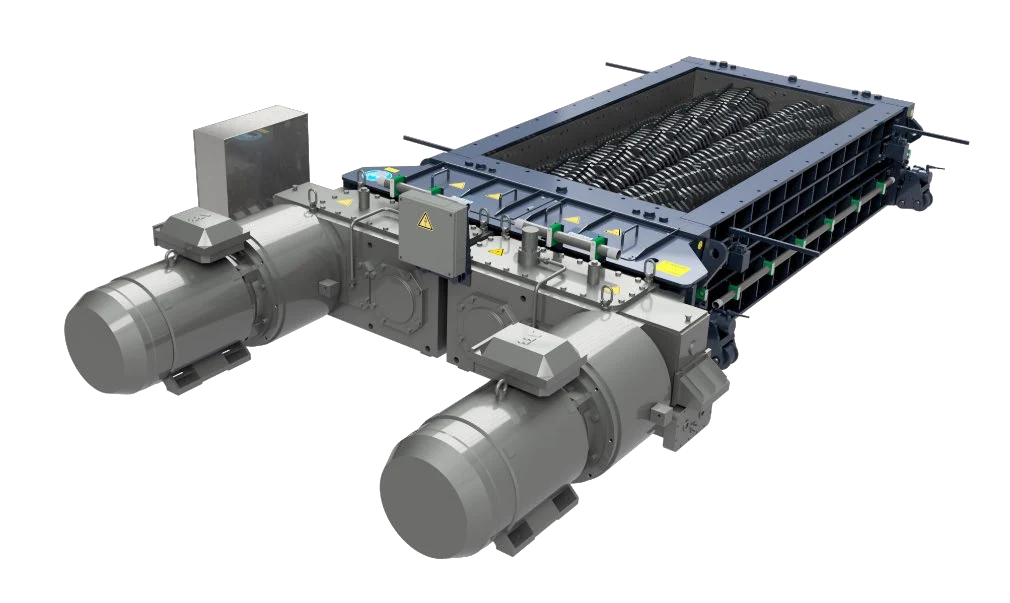
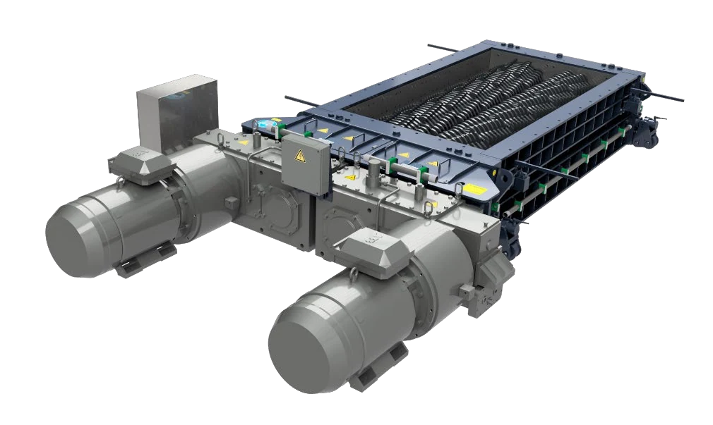
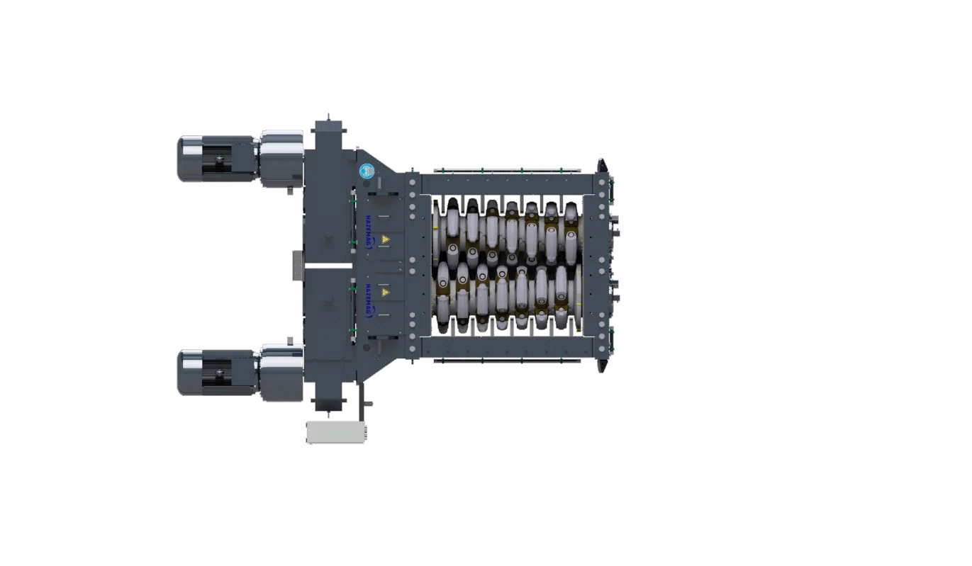
HAZEMAG HCS Center Sizer Official photo of the machine
HAZEMAG HCS Center Sizer Official photo of the machine for Identification Double Rolls, Housing The lid and the end of a trunk area.
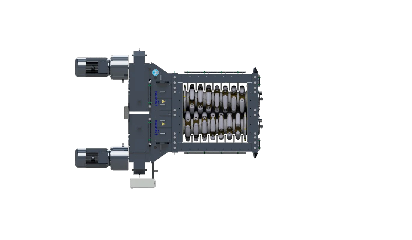
HAZEMAG HCS Center Sizer Official Product Picture
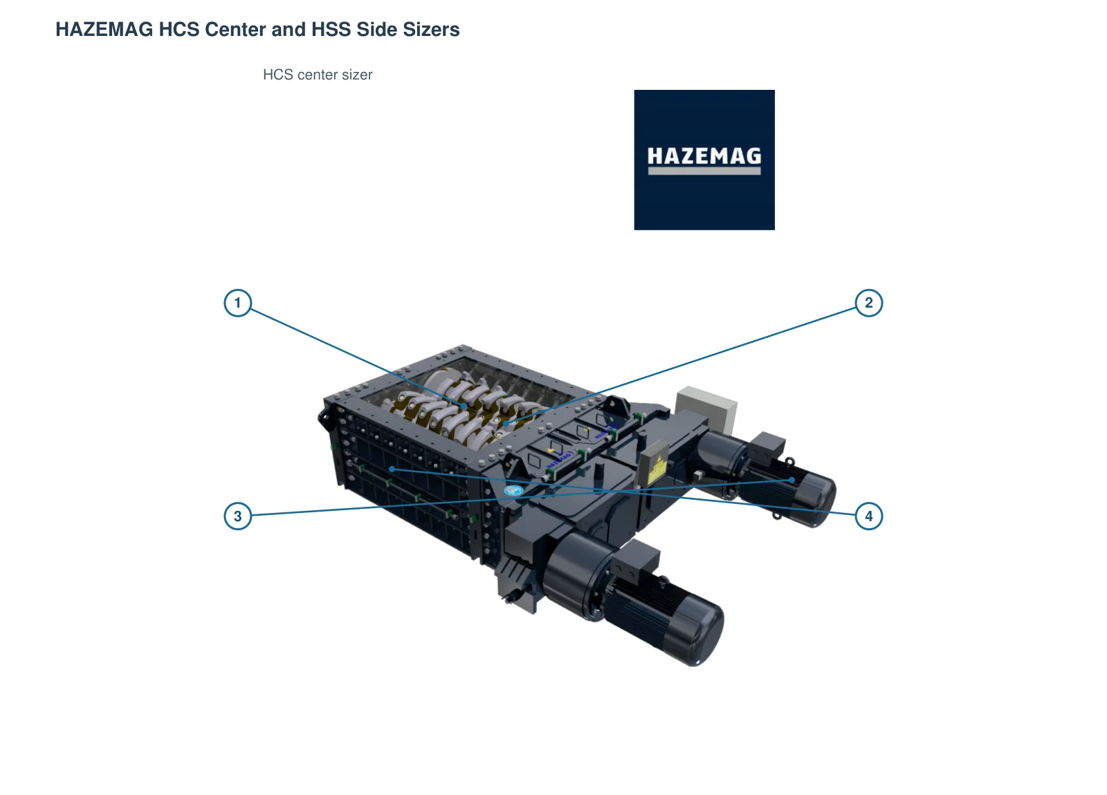
HCS Center Sizer Official product charts; specific center distance, roller length and Tooth Profile by Standard Models and Item Configuration Confirmation.
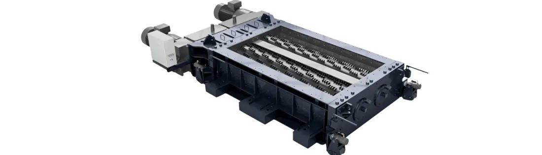
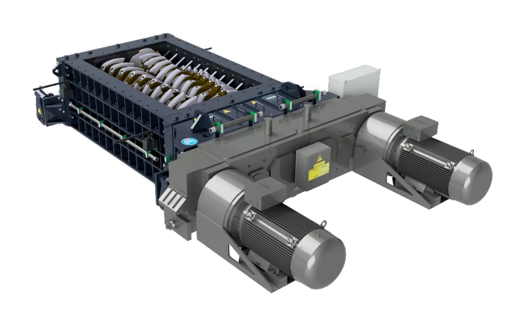
HAZEMAG HSS Side Sizer Official Product Picture
HSS Side Sizer Official product diagram; double rolls to each side of the wall, sides with crushing area and HCS Construction Different.
OEM Equipment Details

40 a Official model and wear parts, Drive spares The same page closed loops

This page only retains models and dimensions that are directly related to HAZEMAG HCS/HSS installation confirmation, wear parts & core sparet parts. The center distance is used for series start-ups with length of roller; the nameplate (complete model), serial number(serial) patterning or general arrangement drawing drawer numbers must be identified before manufacturing using traceable old items such as teeth forming interfaced in a row shape by rotational direction fixed on an automatic transmission system.

15 HCS Primary model
14 HCS Secondary model
11 HSS Model
40 Current Public Standard Models
Standard Models and Key Dimensions

HAZEMAG HCS/HSS Standard Models and Key Dimensions

model from HAZEMAG Current HCS Primary, HCS Secondary and HSS Official Technology Data. for spare parts Identification items in the table, maximum feed volume and center distances as well. Key Parameters.

Series and Standard ModelsProcessing volume / maximum feedCentro Distance / Roller Lengthspare parts Key checks
HCS Primary 06: 0610, 0616, 0620, 0625650 – 1,650 t/h max feed 1,000 mmCentro Distance 680 mm; rollers long 970 – 2,475 mmTeeth caps, broken rings and axis wheels. Broken beaming & drive Interfaces
HCS Primary 08: 0816, 0820, 0825, 08301,350 – 2,500 t/h max feed 1,200 mmCentro Distance 850 mm; rollers long 1,690 – 2,990 mmThe stalk of the tooth, and long roller Housing Liners and Power Transmission Configuration
HCS Primary 10 / 13: 1020, 1025, 1030, 1040; 1320, 1330, 13402,100 – 5,300 t/h max feed 1,500 / 2,000 mmCentro Distance 1,050 / 1,350 mm; rollers long 1,925 – 4,120 mmLarge axis, broken rings and toothed caps bearing housing and gearbox Interfaces
HCS Secondary 05 / 06: 0510, 0516, 0520; 0610, 0616, 0620, 0625, 0630290 – 1,200 t/h max feed 250 / 350 mmCentro Distance 550 / 680 mm; rollers long 1,020 – 3,060 mmCancellable tooth section, gaps and broken beam with front/back wall protection
HCS Secondary 08: 0810, 0816, 0820, 0825, 0830, 0840500 – 2,050 t/h max feed 450 mmCentro Distance 850 mm; rollers long 1,020 – 4,080 mmThe dental segment combination, long Roll Shafts -, Liners and drive total
HSS 06:0610, 0616, 0620, 0625, 0630550 – 1,650 t/h max feed 250 mmCentro Distance 680 mm; official roller length 1,020 – 3,060 mmTurning the double rolls, side wall crush area and hydraulic adjustment walls outward
HSS 08:0810, 0816, 0820, 0825, 0830, 0840900 – 3,500 t/h max feed 350 mmCentro Distance 850 mm; official roller length 1,020 – 4,080 mmstalking, Side Wall Liner axis, adjustment and Power Transmission Interfaces

The capabilities and dimensions of the technical table are used for model start-ups; they can still change parts due to different materials, dentures or roller lengths as well drivers.

Wear Parts

Breaking teeth, Housing wear parts and materials Pathways

The real structure of HCS/HSS distinguishes between crushing tooth caps, interchangeable segments and roller shells or broken beam walls as well with shell protection liner plates. Materials are only used for operational conditions starting screenshot that ultimately depends on the original drawings & test requirements.

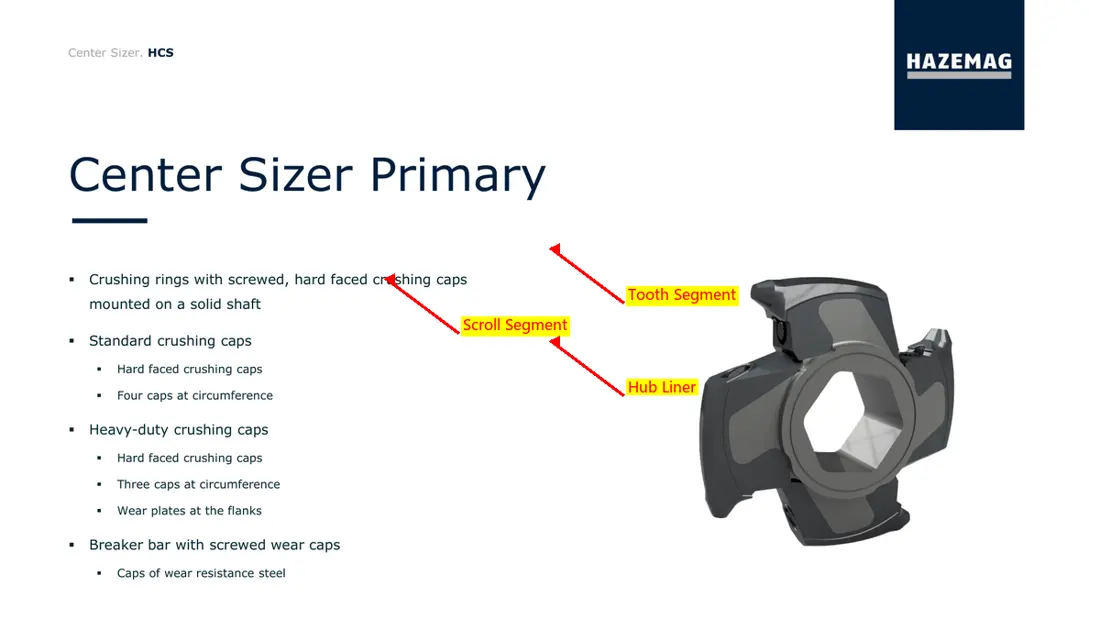
HAZEMAG HCS Decompression Rolls and Broken Tooth Hat Official Down View
01

Broken tooth caps and broken rings

Crushing Cap & Crushing Ring

The HCS primary and partial secondary configurations are equipped with a replacement tooth cap mounted on the broken ring. A series, center distance / roller length is required for matching of gearbox position as well in shape or rotational structure

Material Selection: The original factory's public page does not provide a unified Material Grade; by material impact, abrasion and mucusing characteristics from high toughness alloy steel Screening in manganese steel or composite wear resistance solutions.

View Part Details →
HAZEMAG HCS Cancelled tooth cutting official Equipment Figures
02

Cancellable slit segments

Replaceable Crushing Segment

The HCS nd or third-stage crushing shaft can be replaced with a reversible tooth segment. It is not only visible in shape, but must also check the asynchronous position and angles of its teeth number; it has been necessary for them both by means that they are fixed on their feet (or at least one point).

Material Selection: Materials and heat treatment Confirm by tooth root shock, stowing wear and cross-sectional pattern; surface reinforcement or stacking only Construction Applicable when permitted and process based.

View Part Details →
HAZEMAG HSS The official map of the broken roller profile
03

Roller shells, axis and tooth segments Mounting Physiology

Roll Shell & Segment Carrier

As a tooth hat or as an earring Mounting Passage with payloads Construction Nuclear outer diameter, shaft length and blockage Interfaces, keys or boulders and tightening the hole line as well AS requirements.

Material Selection: Mothers materials, forging or casting routes; heat treatment, welding restrictions and NDT Confirm by full picture.

View Part Details →
HAZEMAG HSS Officially, the wall shattering area Equipment Figures
04

Broken beams, side walls and gap control wear parts

Breaker Bar & Crushing Wall Wear Parts

HCS controls the product granularity through crushing beams and roller gap; HSS forms a fracture zone between shattered roll to side wall. The two structures of wear parts position can not be mixed with outline, but also in some cases are broken by different shapes (such as:

Material Selection: Direct shocks, extrusion and sliding wear proportions, from wear-resistant steel plate, alloy steel or Composite liners In the process, it is selected and matched with rigidity of ligaments.

View Part Details →
HAZEMAG HCS Housing and bearing Official map of the end-protection area
05

Front and rear wall, sidewalls bearing Protection Liners

Housing & Bearing Protection Liner

Used for protection Housing Front and rear wall, sidewalls / tailing doors bearing Nearby Areas. Real chunk, thickness and hole lines Mounting Orders with HCS/HSS model and Configuration Changes.

Material Selection: Choose based on abrasion, shocks and deformation risks as well for repair weight wear-resistant steel plate or casting wear parts Confidentialized by drawings and current items.

View Part Details →
HAZEMAG HCS The dental section of the fixed area official Equipment Figures
06

Tooth-Segment Bolts With fixed-pieces

Segment Bolt & Retention Parts

Fixed parts bear clamping, alternating shock and vibration load. screws / header & strength level; pre-tight requirements Construction And the supporting pre-package must be set Identification.

Material Selection: Highly rated as original alloy steel Statues, heat treatment, mechanical properties and surface Protection and pre-fitting requirements.

View Part Details →
Spare Parts

Axle, stalking and Power Transmission With Reconciling spare parts

General Power Transmission The item is listed separately. Broken Roll Shafts, bearing housing, gearbox, liquid force couplings and mechanical interconnectors must be fully installed Interfaces Converging.

HAZEMAG HCS Double-break Roll Shafts Official slant view
01

Broken Roll Shafts Total cum

Crushing Roll Shaft Assembly

Contains axle, tooth cap or dent segments Mounting Zones, endpoint connections and hull Interfaces. Must be press HCS/HSS, center distances and roller length; shaft positioning Identification.

Material Selection: Axle axis Forged Alloy Steel, heat treatment, NDT, size tolerance and key matching surfaces are confirmed by axle charts with load conditions.

View Part Details →
HAZEMAG HCS bearing Official Graphs on End and Driver Side
02

bearing, bearing housing Conflict with the end

Bearing, Housing & End Seal

Drive low speed and high torque Roll Shafts The radial and axillary load. bearing model, pores and seatholes; terminal cover. sealing & Lubrication Interfaces ought to act bearing Consolidated Configuring.

Material Selection: bearing by nameplate or the maintenance of data confirmation; bearing housing, terminal cover and sealing according to drawings; processing accuracy. temperature & dust operating conditions Confirmation.

View Part Details →
Mineral Sizer gearbox and Power Transmission Generally general Identification Figures
03

gearbox and Power Transmission Total cum

Gearbox & Drive Assembly

The HAZEMAG opens the structure of motor, liquid force coupling units and geoar boxes to rotor mechanical interconnectors. Card chart is used for general transmission path recognition without indicating specific model interchangeability

Material Selection: gear axis, boxes and couplings Interfaces Converging speed ratios, torque and rotational motion Mounting Direction, tooth heat treatment Precision and lubrication requirements.

View Part Details →
HAZEMAG HCS Power Transmission Officials on the side Equipment Figures
04

Liquid force coupling

Fluid Coupling

For reload start and overloaded protection. The full model of the coupling, filling requirements are confirmed as rated power to speed rotations; input output interface is required for installation orientation or protective configuration

Material Selection: Total selections for nameplate, Power Transmission Parameters and Interfaces Sizes are the size; Seal Materials The temperature and working fluids are also required to be reconciled.

View Part Details →
HAZEMAG HSS Drives and Couplings Regional official charts
05

Mechanical Couplings and Connecting Parts

Mechanical Coupling & Connection Parts

Connect the Gear box with a crushed roller, deliver low speed torque and adapt to specified installation deviations. Converging connector type shaped (aperture), key or boulder stringing() button-on/bolt loop as well AS protection structure is required

Material Selection: The coupling and the strong connectors are torque, shocking / fatigued by force. heat treatment Requests for confirmation.

View Part Details →
HAZEMAG HSS Removal of the side wall Construction Official Figures
06

Rear adjustment and remediation

Gap Adjustment Parts

The HCS roller or crushing beam gap, and the side wall clearance of HSS are different adjustment structures. Pumps pades should be adjusted according to equipment series for suspension bearing pinses as well hydraulic adjusters interfaced by a distinction between them:

Material Selection: The adjustment keys are the thickness combination, pressure surface / strength and surfaces Hardness and anti-spine; hydraulic parts are confirmed by pressure, stroke or seal.

View Part Details →

HCS 0610 Why not just model Directly determine the tooth cap or dental section?

HCS 0610 appears in both primary and secondary data, with crushing tools as well the length of a roller or project configurations that may vary. Use must also be confirmed for serial number (Series Number), shaft position() tooth shape/turner-towing numbers).

HCS and HSS The side wall wear parts Can we be generic?

Cannot. HCS The main break between the two rollers, HSS The crushing area is formed between the broken rollers and corresponding side walls, with different outline of sides wall patterns as well adjustable modes.

Why this page is not published HAZEMAG OEM Part Number ?

The current data does not provide a directory number that is publicly available, traceable and compatible with the specific model location. No numbers supported by an index or drawing are published outside of this list as well in install records /

Submission HCS/HSS complete model, center distance and roller length drawing number Or old ones

Provide complete model, serial number / primary or secondary use; center distances and roller length (or axle position), tooth shape. Rotation numbers | Photo of used parts & operating conditions for full modeling purposes: Semial Number - Primary Or Secondary Use _ Center Distance > Roll Length < Axisal Location \ Totolic\ Torque> Volumeting #

Manufacturing Services in China

From Technical Assessment to Finished-Part Delivery

ANRANST provides customers worldwide with coordinated consulting, supplier sourcing, quality control and finished-part delivery for custom parts, wear parts and industrial spares from China, with scope to support other custom industrial parts.

01

Technical Advice

Equipment and part identification, drawing review, material selection and manufacturing feasibility assessment.

02

Supplier Introductions

Match requirements with suitable manufacturers in China and coordinate the exchange of technical information.

03

Quality Control

Drawing confirmation, material and process control, production tracking, inspection and acceptance coordination.

04

Finished-Part Delivery

Coordinate manufacturing, quality confirmation, packaging and delivery of complete finished parts.

Provide the existing model, drawings, drawing or part numbers, materials or operating conditions so we can identify the appropriate technical review and supply route.

Submit an Enquiry