
01
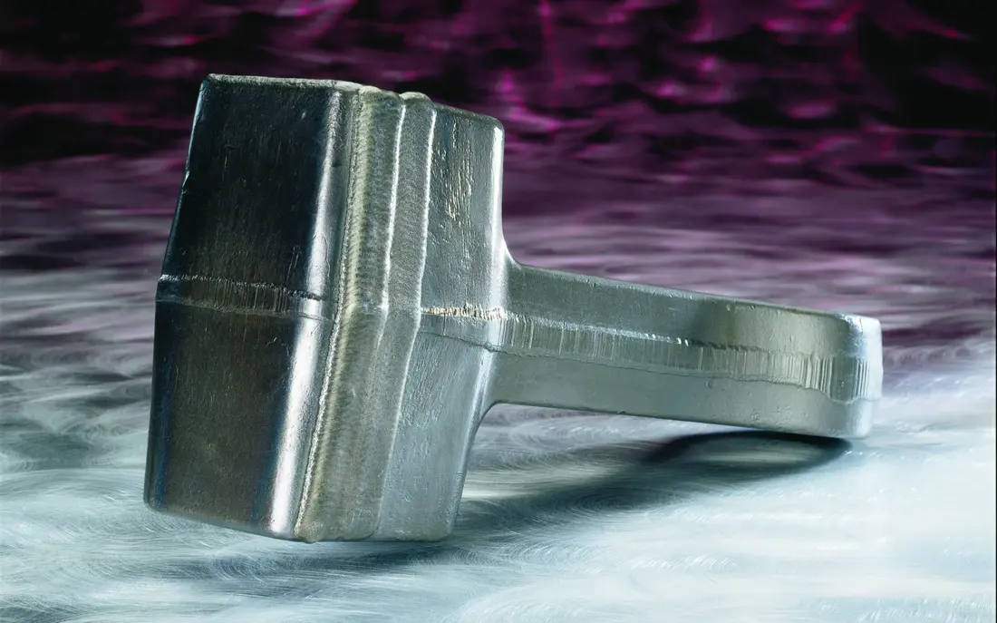
Swing Hammer System
Swing Hammer System
Hammers swing freely between the rotor discs and directly impact the feed. Check hammer shape, quantity, swing clearance and fastening separately for HDS, HUM, HNM and HUV.
View Part Details →Review 38 current HDS double-shaft hammer crusher and HUM, HNM and HUV hammer mill models, including rotor arrangements, hammers and pins, grate baskets, liners, shaft assemblies and drive spares.
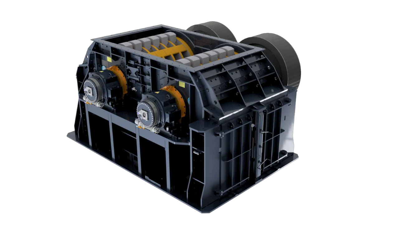
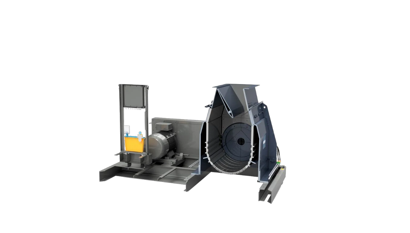
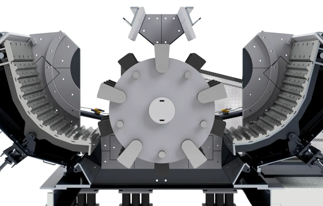
This page distinguishes the HDS double-shaft hammer crusher, HUM single reversible-rotor hammer mill, HNM twin non-reversible-rotor hammer mill and HUV variable-rotor hammer mill. It focuses on spare-part identification, material selection and manufacture to drawing.
The table uses current official HAZEMAG HDS, HUM, HNM and HUV data. Capacity supports initial series screening; actual performance depends on feed material, particle size and configuration.
| Series and Standard Models | Rotor Design / Key Dimensions | Feed Size / Capacity Range | Key Spare-Part Checks |
|---|---|---|---|
| HDS: 1412, 1414, 1416, 1418; 1613, 1615, 1618, 1620; 1818, 1821, 1823, 1825; 2019, 2022, 2025, 2028, 2032 | Twin rotors; diameter 1,400–2,000 mm, width 1,200–3,160 mm | Maximum feed edge length 1,000–1,600 mm; published capacity approximately 180–2,450 t/h | Hammers, hammer pins, centre anvil, grate bars and baskets, twin-rotor shaft assemblies |
| HUM: 0703, 0705, 0708, 1008, 1013, 1313 | Single reversible rotor; Ø650–1,300 × 250–1,250 mm | Approximately 5–50 t/h at 95% below 3 mm; 15–250 kW | Hammers, rotor discs, grinding path, grate plates, casing liners and V-belt drive |
| HNM: 0703, 0705, 0708, 1008, 1013, 1020, 1313, 1325 | Twin non-reversible rotors; Ø650–1,300 × 250–2,500 mm | Approximately 10–190 t/h at 95% below 3 mm; twin-motor configuration | Twin-rotor positions, hammers and pins, grinding path, grate plates and bearing supports |
| HUV: 1013, 1020, 1313, 1622, 1626, 1630, 1634 | Variable single rotor; feed opening approximately 376–690 × 1,220–3,400 mm | Maximum feed size 120–280 mm; published capacity approximately 110–510 t/h | Rotor configuration, hammers, impact and grinding path, casing liners and drive interfaces |
| Legacy Series: Unirotor and Novorotor | OEM-listed predecessors of HUM and HNM respectively | Confirm legacy dimensions and configuration using the specific nameplate, year and drawings | Do not substitute current-series dimensions, hammers or rotor designs directly |
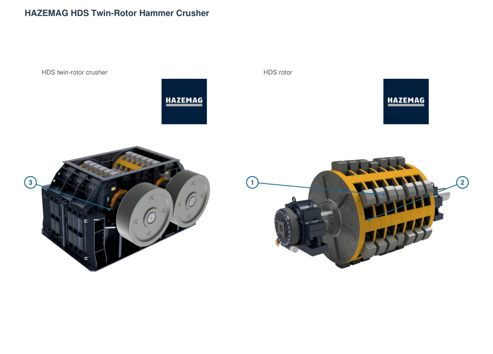
The numbers on the diagram correspond one to one with the rows below.
| No. | Component | Location | Applies to | |
|---|---|---|---|---|
| 1 | 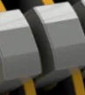 | Hammer | Hammer at perimeter of separate rotor | HDS |
| 1 | Hammer | Exposed swing hammer | HNM | |
| 2 | 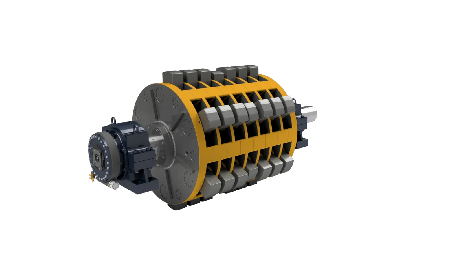 | Rotor assembly | Separate OEM rotor assembly | HDS |
| 2 | Rotor assembly | Disc rotor in opened chamber | HNM | |
| 3 | Housing | Twin-rotor crusher housing | HDS | |
| 3 | Housing | Housing outside rotor | HNM |
Six component groups cover direct impact, load transfer, impact and grinding surfaces, and screened discharge. Each group links to materials and common part pages.
Swing Hammer System
Hammers swing freely between the rotor discs and directly impact the feed. Check hammer shape, quantity, swing clearance and fastening separately for HDS, HUM, HNM and HUV.
View Part Details →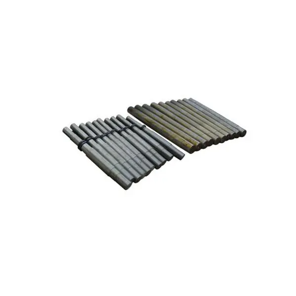
Hammer Pin & Retention Parts
Connects swing hammers to rotor discs while carrying alternating impact, bending and wear. Check diameter, length, end locking, disc spacing, hammer bore and removal direction.
View Part Details →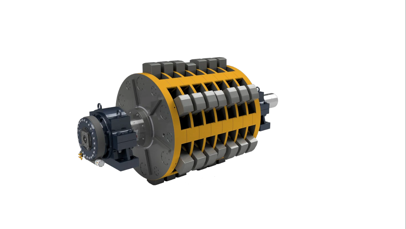
Rotor Disc, Spacer & Ring
Rotor discs are arranged along the shaft to position the hammers and transfer loads; spacers and rings control disc spacing. Check disc count, thickness, hole pattern, shaft fit and axial location as a set.
View Part Details →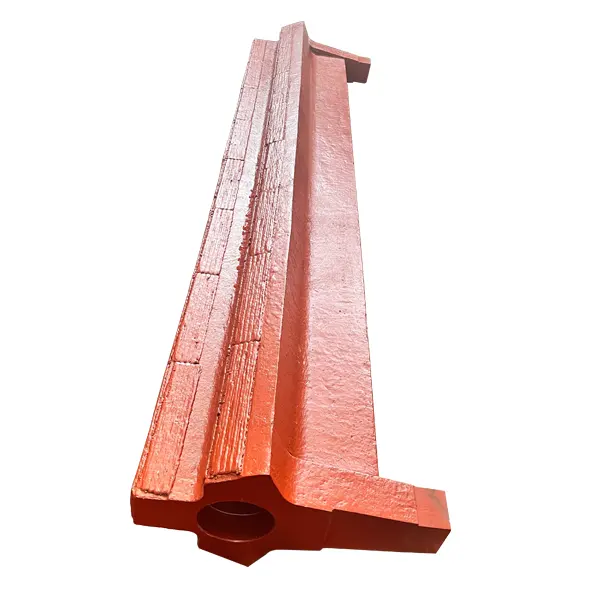
Central Anvil, Impact Wall & Housing Liner
The HDS centre anvil lies between the two rotors. HUM, HNM and HUV use impact surfaces and casing liners according to their designs. Installation positions, profiles and load paths differ between series.
View Part Details →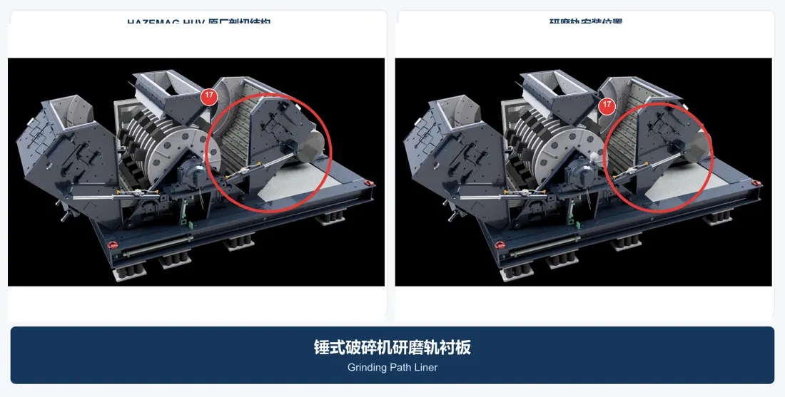
Grinding Path Liner & Spacer Bar
Provides secondary impact, fine crushing and product-size control. Presence, bar count, spacing and curvature depend on the specific HUM, HNM or HUV duty.
View Part Details →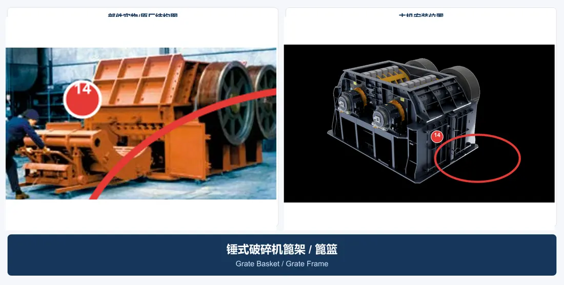
Grate Bar, Segment & Basket
The HDS grate basket retains oversized particles and can be withdrawn with its frame for maintenance. HUM and HNM may use different grate plates or screens. Check openings, gaps, curvature, segmentation and supports.
View Part Details →Drive components are listed separately. Check rotors, main shafts, bearing housings, pulleys, V-belts and grate-basket trolleys against the specific series and installation interfaces.
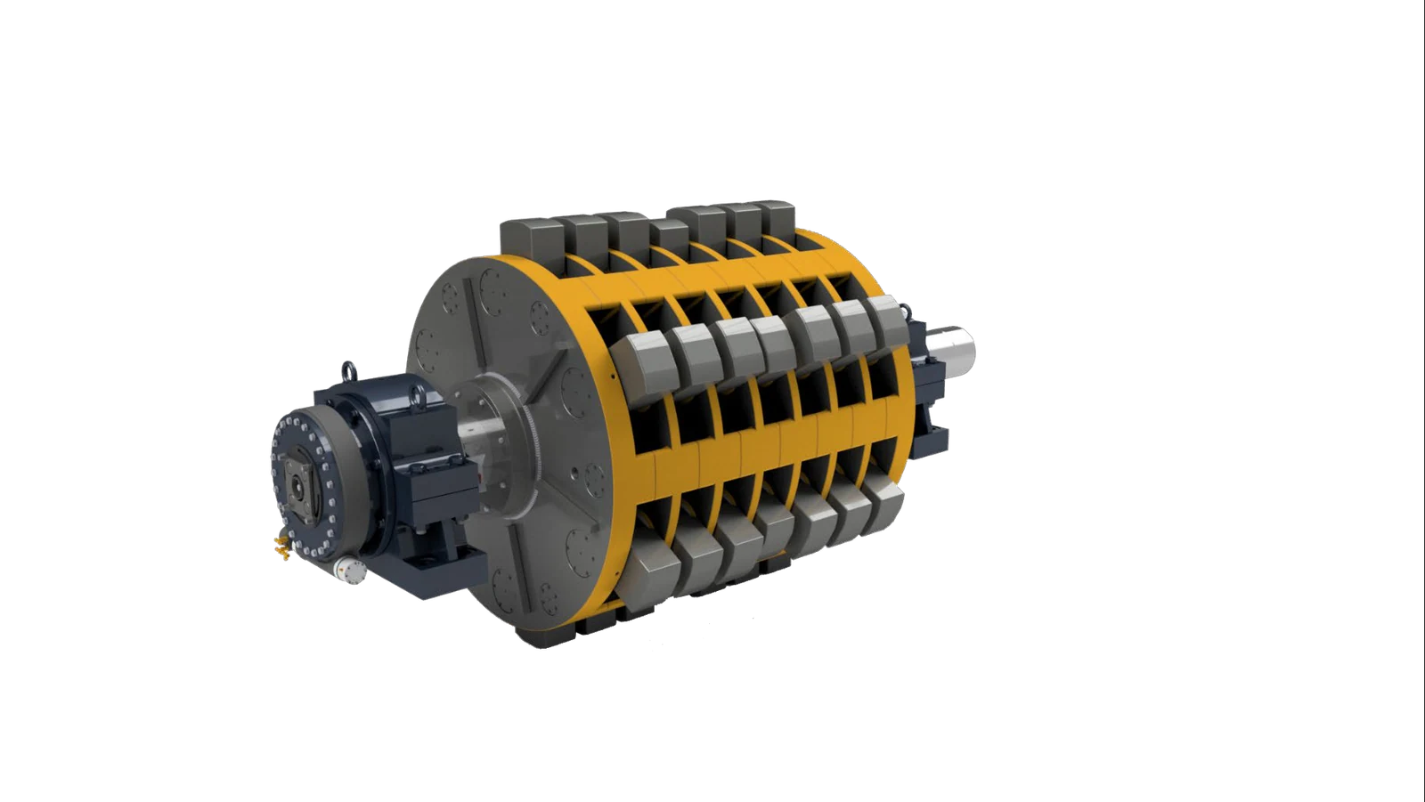
Rotor Assembly
HDS has twin rotors, HUM and HUV have single rotors, and HNM has twin non-reversible rotors. Identify each by series, rotor position, rotation, disc count, hammer arrangement and shaft-end interfaces.
View Part Details →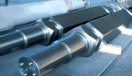
Rotor Shaft
Transmits drive torque and carries hammer impact loads. Check shaft ends, bearing and seal seats, key or locking-assembly interfaces, disc-pack fits, rotation and dynamic balance requirements.
View Part Details →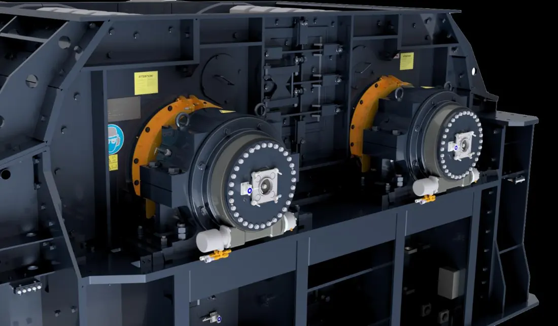
Rotor Bearing, Housing & Seal
Supports the impact rotor and maintains shaft position. Check bearing designation, clearance, housing bore, end covers, temperature monitoring, seals and lubrication interfaces as a set.
View Part Details →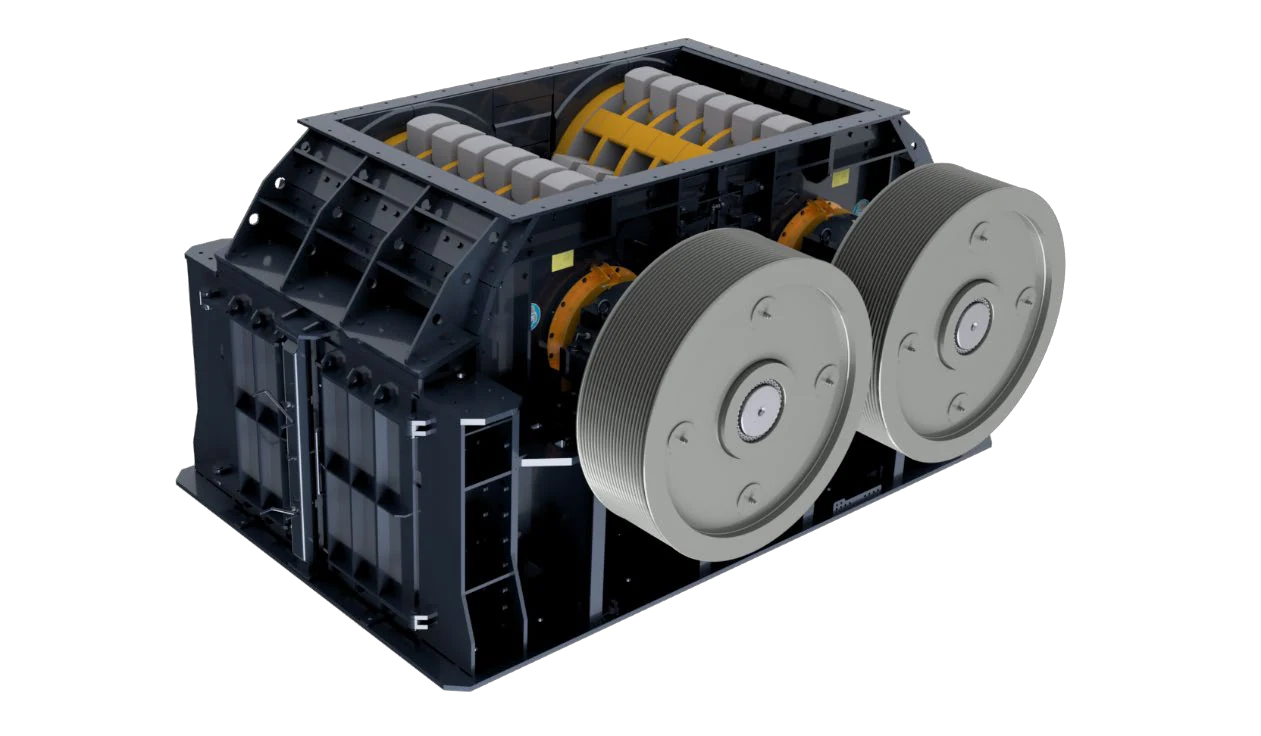
Drive Pulley
The official HUM drive comprises motor and rotor pulleys with matched high-performance V-belts. Check other series against their drive configurations. Confirm diameter, groove profile, bore, key and rotation.
View Part Details →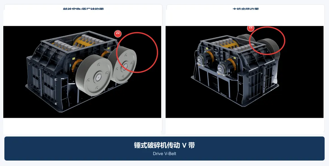
V-Belt Set & Tension Interface
Confirm V-belts as a matched set by cross-section, effective length, belt count, matching tolerance, pulley groove profile and centre distance. Do not mix batches or replace only one belt.
View Part Details →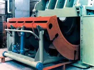
Grate Basket Trolley, Roller & Guide
The HDS grate basket can be withdrawn from the casing on its frame or trolley. Check rollers, rails, pins, stops and supports as a set against machine width and maintenance direction.
View Part Details →No. Rotor count, rotation, disc spacing, hammer pins, swing clearance and operating conditions differ. Confirm each part against the full model, rotor position, dimensions, drawing and worn part.
They are part of the drive train. Dimensions, groove profile, belt count, matching and dynamic balance directly affect rotor operation, so they require their own identification details.
The available material does not provide traceable catalogue numbers matched to specific models and positions. Numbers without catalogue, drawing or installation-record support are not published.
Provide the full model, serial number, rotor count and rotation, rotor dimensions, part position, drawing, worn-part photographs, material and operating conditions. These support identification, material assessment, manufacturing coordination, quality control and finished-part delivery.
Or contact us directly: +86 156 3797 3199
zzx@anranst.com
ANRANST provides customers worldwide with engineering assessment, production at certified foundries to the customer technical requirements, quality control and finished-part delivery for custom wear parts and industrial spares, with scope to support other custom industrial parts.
We review mating surfaces and interface dimensions and assess material, heat treatment and manufacturing feasibility.
Material grades and heat-treatment processes are specified order by order, stated in the technical agreement and tracked through production.
Drawing confirmation, material and process control, production tracking, inspection and acceptance coordination.
We coordinate manufacturing, quality confirmation, packaging and delivery of complete finished parts in a workable, closed-loop supply process.
Provide the existing model, drawings, drawing, materials or operating conditions so we can identify the appropriate technical review and supply route.
Submit an Enquiry