FLS KREBS Slurry Pumps: millMAX, slurryMAX, UMD and Related Series

Identify the pump series and size, then review impellers, volutes and liners, throatbushes, front and rear liners, adjustable wear rings, shafts, seals, bearings, materials, drawing numbers and maintenance tools.

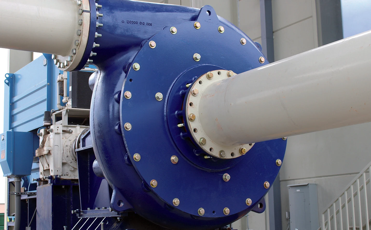
Installed FLS KREBS millMAX slurry pump in OEM documentation
Installed millMAX pump shown in the official FLS manual, with the metal wet end, suction inlet, discharge outlet, casing and power end visible.
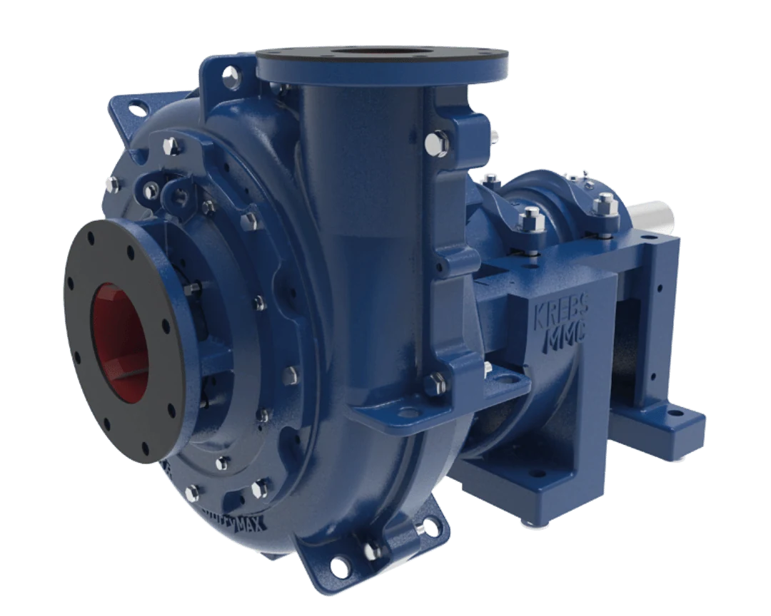
Installed FLS KREBS slurryMAX slurry pump in OEM documentation
Installed slurryMAX split-casing pump shown in the official FLS manual. Its outer casing, liners and wet-end arrangement differ from millMAX.
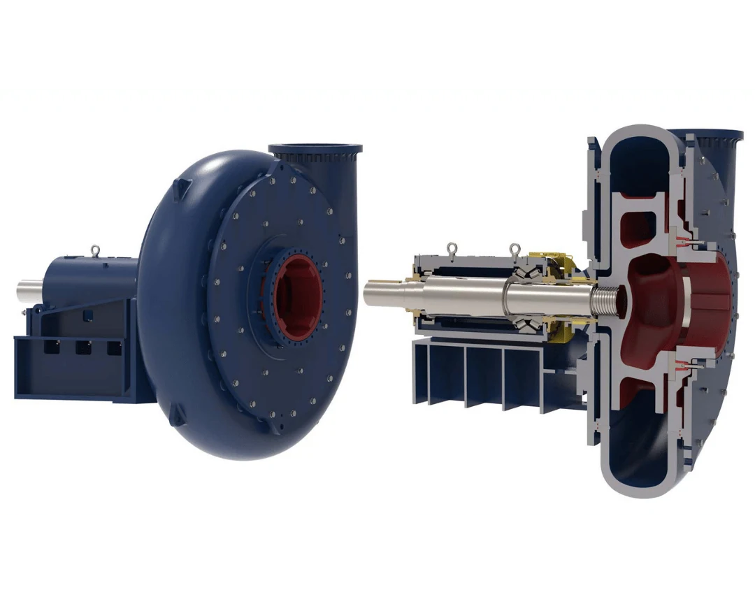
Installed FLS KREBS UMD mill discharge pump in OEM documentation
Installed UMD mill discharge pump shown in the official FLS manual, for checking the large wet end, piping and base arrangement.
OEM Equipment Details

Pump Series, Sizes, Wet-End Parts, Drive Spares and Maintenance Tools

The same pump size does not establish part interchangeability. Before quoting, match the series, full size, suffix, pressure rating, rotation, discharge orientation, impeller, casing and liners, wear ring, shaft seal, power frame and drawings to the same pump.

9 Verified Series Identification Entries
6 Core Wet-End Wear Parts
5 Drive and Seal Components
2 OEM Maintenance Systems
Series, Models and Key Dimensions

millMAX, millMAX-e, slurryMAX, UMD and Related Pumps

Standard sizes come from current FLS KREBS manuals and support equipment identification. They do not replace hydraulic selection or establish wet-end part interchangeability.

SeriesDesign / VersionStandard Sizes or RangeMain ApplicationsRequired spare identification
millMAXHeavy-duty metal wet end3×2, 4×3, 6×4, 8×6, 10×8, 12×10, 14×12, 16×14, 18×16, 20×18, 24×20, 28×26Mill discharge and highly abrasive slurry; adjustable wear ring for suction-side sealingConfirm pump size, impeller, casing, wear ring, rotation, discharge orientation and power frame together
millMAX HP / HHHigh pressure / high headHP:14×12, 20×18, 24×20; HH:3×2, 4×3, 6×4, 8×6, 10×8, 12×10Multistage high-pressure or high-total-head duties; HP is suitable for applications above 500 psi (35 bar)Do not substitute parts solely by standard millMAX size; check casing pressure rating and concentric or volute design
millMAX-eCompact, efficient medium-duty pump2×1.5, 3×2, 4×3, 6×4, 8×6, 10×8, 12×10, 14×12, 16×14Mineral sands, alumina, extraction, dilute media, seal water, fine coal, thickener overflow and tailings return waterCheck impeller diameter, wear ring, casing, shaft seal, power frame and motor configuration
slurryMAXHeavy-duty split casing3×2, 4×3, 6×4, 8×6, 10×8, 12×10Replaceable liners and a choice of impeller materials, with an adjustable wear ringConfirm standard / XD / HP / XHP series, liners, outer casing and pressure rating
slurryMAX XD / HP / XHPExtra-duty / high-pressure split casingXD: 2×2 to 20×18; HP: 4×4 to 16×14; XHP available in 16×14Highly abrasive duties, cyclone feed, tailings and multistage high-pressure applicationsXD, HP and XHP differ in casing strength; confirm wet-end materials and part numbers using the full suffix
UMD Ultimate Mill DischargeHeavy-duty mill discharge pump6×5, 8×6, 10×8, 12×10, 14×12, 16×14, 18×16, 20×18, 22×20, 26×22, 28×26, 32×28, 34×32, 38×34Hard-rock mill discharge; published flow range 50–20,000 m³/hCheck standard / high-pressure / fully rubber-lined version, rotation, liners and wet-end drawings
gravelMAXSlurry pump for large particlesConfirm against project selection documentsWide passages and large-particle handling for abrasive slurry containing coarse solidsCheck impeller passages, particle size, suction inlet, casing and discharge orientation
hMAXHorizontal recessed-impeller pumpConfirm against project selection documentsDuties involving entrained air, shear-sensitive products, fibres or large particles; concentric casing and large internal clearancesThe recessed impeller differs from the standard millMAX wet end; appearance alone does not establish compatibility
vMAX / vMAX-RVertical cantilever pumpConfirm against project selection documentsSumps, aerated slurry and solids handling; published maximum particle size is up to 56 mm, depending on modelCheck immersion depth, vertical shaft, impeller, liners, bottom suction arrangement and mounting frame
Wear Parts

Impellers, Casings, Liners, Throatbushes and Adjustable Wear Rings

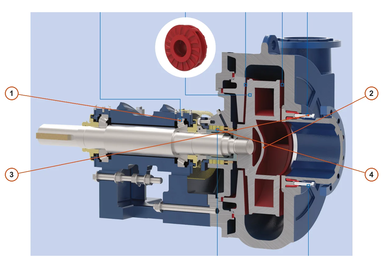
Follow the slurry path from the suction inlet through the impeller to the volute discharge. Each component links to its common part page and relevant material page.

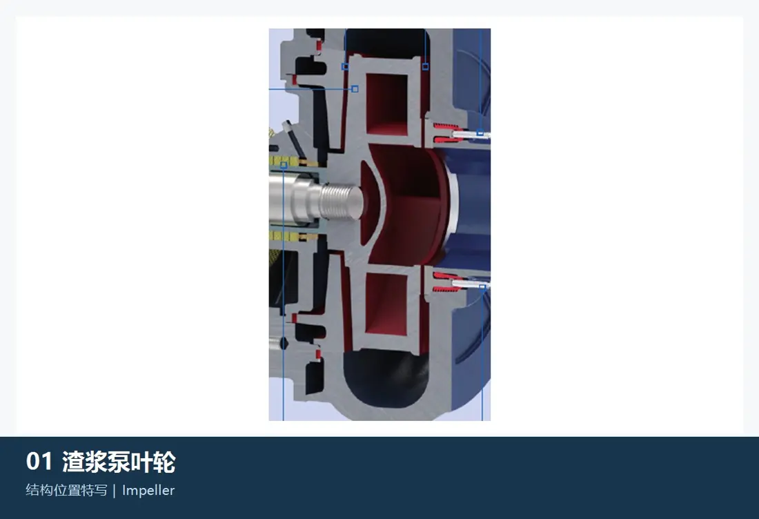
Impeller position and arrangement in an FLS KREBS slurry pump
01

Impeller

Impeller

The main rotating wet-end component. Check pump series and size, impeller outside diameter, width, blade count, rotation, passages, eye, threaded or shaft connection, balance grade, discharge orientation and duty point.

Material and manufacturing checks:FLS lists high-chromium alloys, elastomers and polyurethane for wet-end components, with tungsten carbide laser cladding available for extreme abrasion. Confirm material against particle size, concentration, corrosion, speed and the original design.

View Part Details →
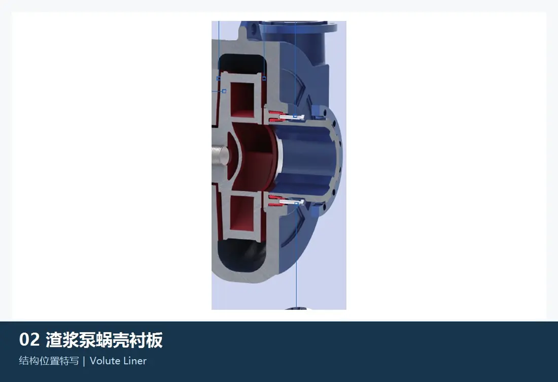
Volute and casing liner position and arrangement in an FLS KREBS slurry pump
02

Volute / Casing Liner

Volute / Casing Liner

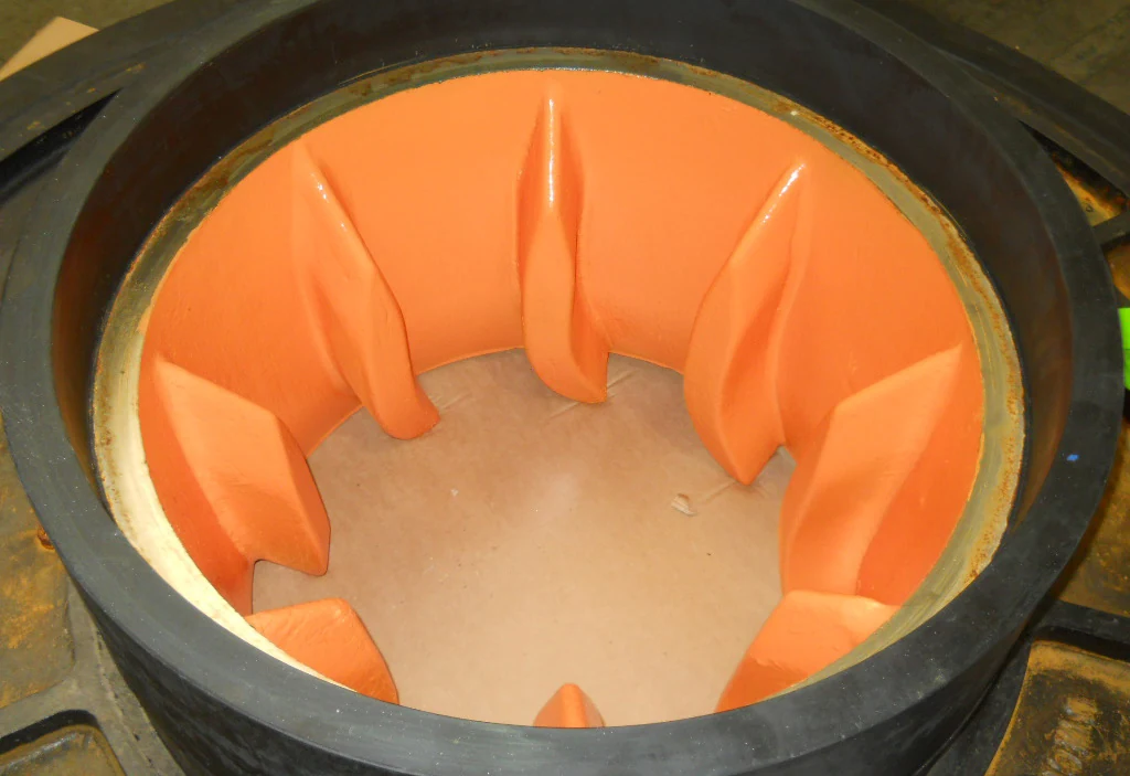
Contains high-velocity slurry leaving the impeller and forms the discharge passage. Check the millMAX metal casing or slurryMAX / UMD split-casing design, pump size, rotation, discharge orientation, liner segmentation, thickness and flanges.

Material and manufacturing checks:Select high-chromium wear alloys, elastomers or polyurethane according to coarse-particle impact, fine-particle abrasion, corrosion, pressure and allowable impeller peripheral speed.

View Part Details →
Throatbush and suction bushing position and arrangement in an FLS KREBS slurry pump
03

Throatbush / Suction Bushing

Throatbush / Suction Liner

Located at the suction inlet ahead of the impeller eye; together with the adjustable wear ring, it affects suction-side clearance. Check pump size, bore, profile, register, thickness, hole pattern, wear-ring interface and front impeller clearance.

Material and manufacturing checks:Confirm high-chromium alloy, elastomer or polyurethane against suction velocity, particle abrasion, impact and compatibility with the wear ring.

View Part Details →
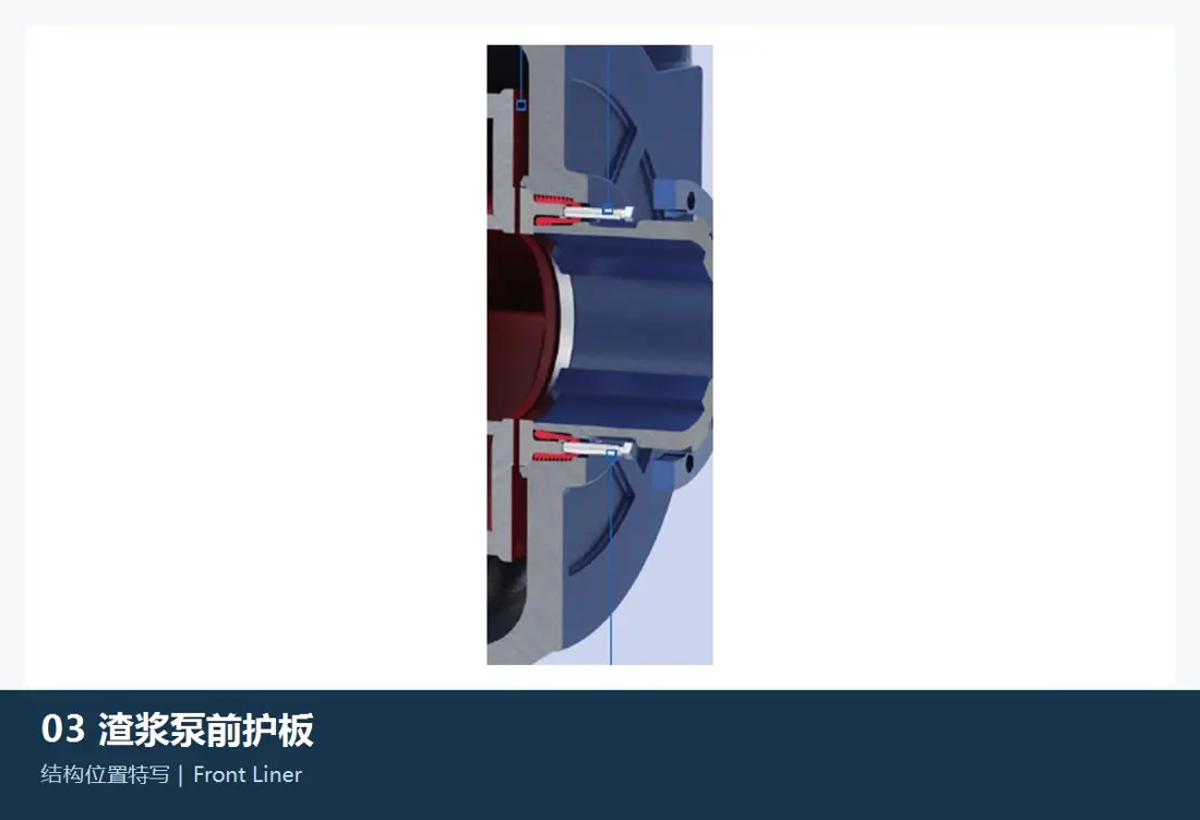
Front liner position and arrangement in an FLS KREBS slurry pump
04

Front Liner / Front Cover Liner

Front Liner / Frame Plate Liner

Protects the suction-side casing and forms the wet end with the throatbush, impeller and sealing faces. Check series, size, internal profile, thickness, hole pattern, seal grooves, wear-ring interface and assembly orientation.

Material and manufacturing checks:Select the material together with the casing, impeller, throatbush and slurry duty. Matching pump size alone does not establish interchangeability.

View Part Details →
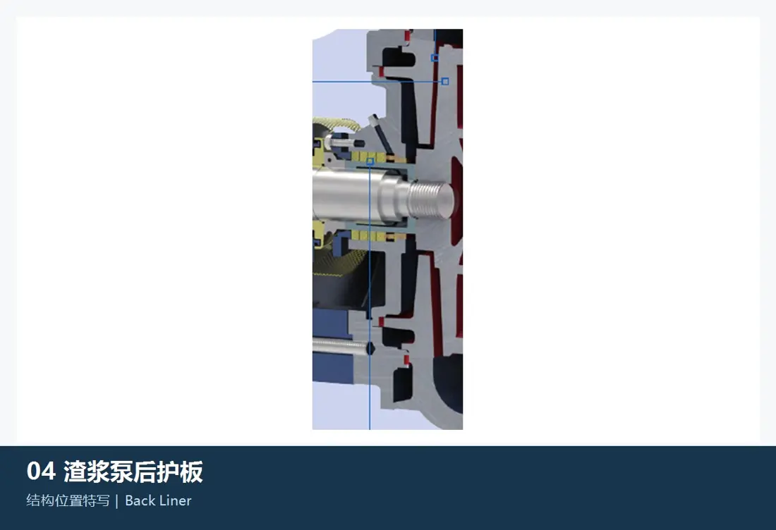
Rear liner position and arrangement in an FLS KREBS slurry pump
05

Rear Liner / Rear Cover Liner

Back Liner / Cover Plate Liner

Located on the drive side, it controls rear impeller clearance and protects the area near the shaft seal. Check series, size, shaft bore, internal profile, thickness, sealing interface, fixing method and rear clearance.

Material and manufacturing checks:Confirm high-chromium alloy, elastomer or polyurethane against abrasion, corrosion, shaft-seal type and casing design.

View Part Details →
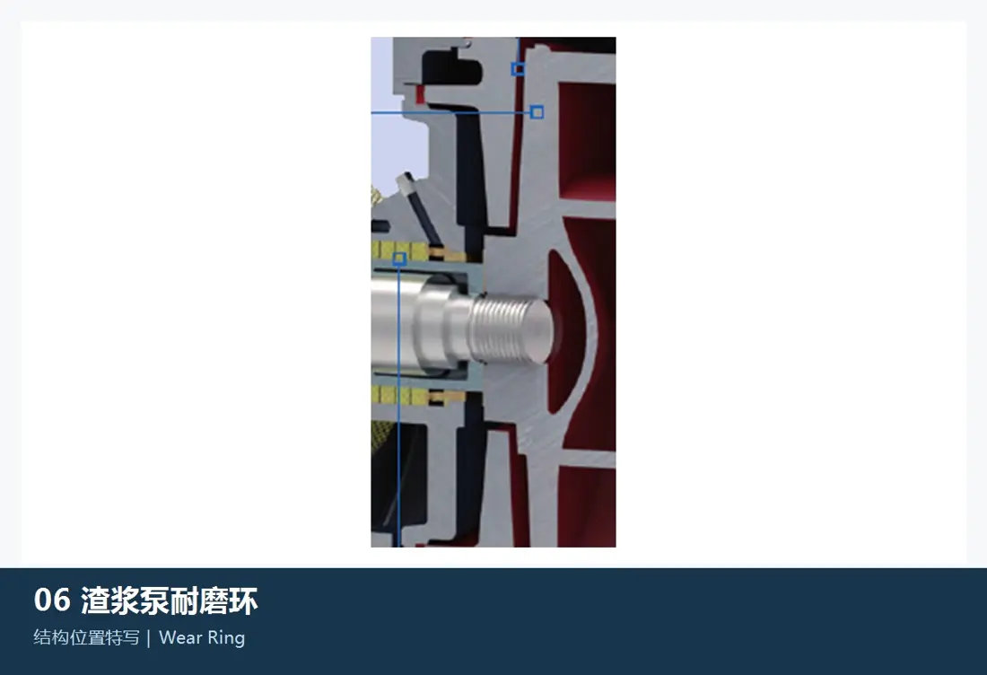
Adjustable wear ring and lantern ring position and arrangement in an FLS KREBS slurry pump
06

Adjustable Wear Ring / Lantern Ring

Wear Ring / Lantern Ring

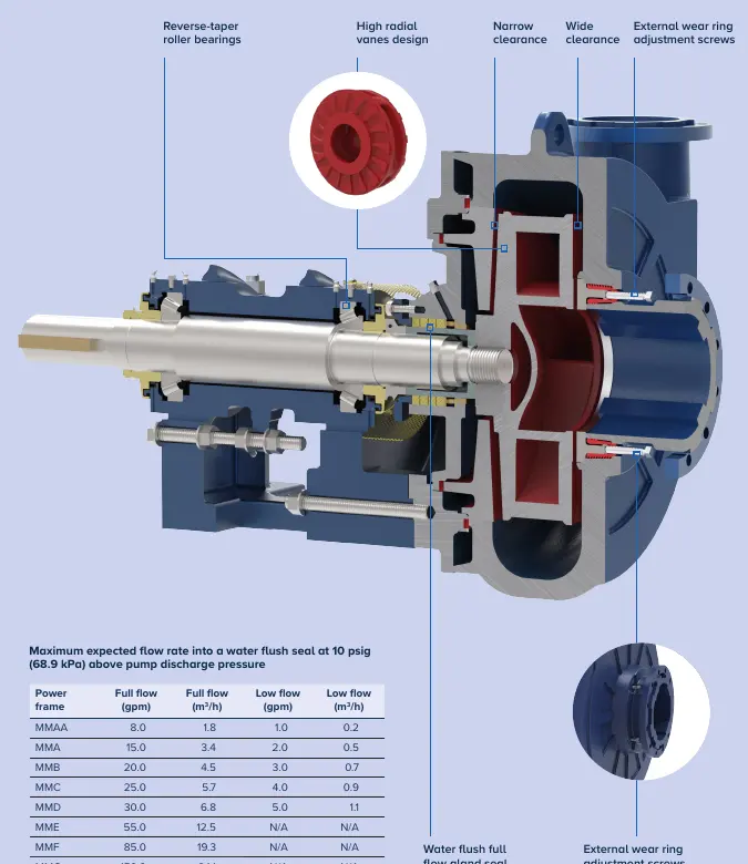
The millMAX adjustable wear ring controls suction-side clearance during operation. The lantern ring belongs to the shaft-seal water circuit. Their functions and designs differ, so identify each by its assembly position.

Material and manufacturing checks:Match wear-ring material to the impeller, throatbush and speed. Match lantern-ring material to seal water, corrosion, shaft sleeve and packing system.

View Part Details →
Spare Parts

Shafts, Sleeves, Expellers, Seals, Bearing Assemblies and Power Frames

Identify drive and seal components separately, focusing on power-frame and bearing designations, shaft and housing fits, seal arrangement, lubrication and alignment with the wet end.

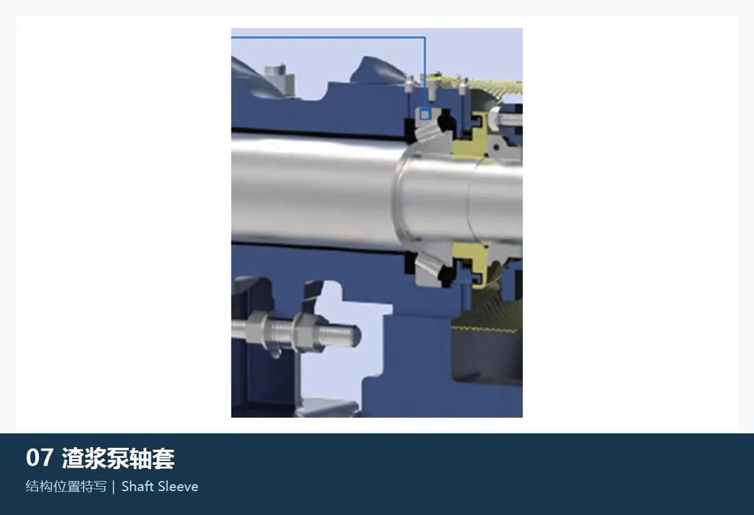
Pump shaft and shaft sleeve position and arrangement in an FLS KREBS slurry pump
01

Pump Shaft and Shaft Sleeve

Pump Shaft and Shaft Sleeve

The pump shaft transmits torque; the sleeve protects the seal area. They are separate components. Check series, power-frame designation, overall length, shaft diameter, bearing seats, threads, keys, impeller connection, sleeve bore and outside diameter, sealing surfaces and rotation.

Material and manufacturing checks:Specify a verified alloy steel for the shaft, with fatigue, accuracy and non-destructive testing requirements. Confirm the sleeve against wear, corrosion, seal compatibility and surface treatment.

View Part Details →
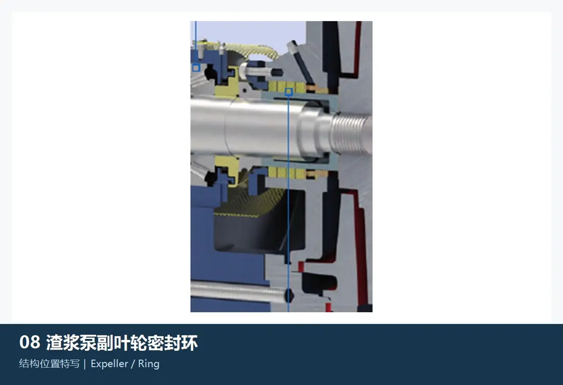
Expeller and expeller ring position and arrangement in an FLS KREBS slurry pump
02

Expeller and Expeller Ring

Expeller and Expeller Ring

The rotating and stationary components of a centrifugal dry shaft seal. Check pump size, power frame, sleeve, inside and outside diameters, vanes, clearances, rotation, casing, material and target pressure differential.

Material and manufacturing checks:Confirm wear alloy, elastomer or corrosion-resistant material against speed, slurry, seal pressure differential and the original seal design.

View Part Details →
Stuffing box liner position and arrangement in an FLS KREBS slurry pump
03

Stuffing Box Liner

Stuffing Box Liner

Located where the shaft passes through the casing, supporting packing, the lantern ring or associated seal components. Check series, power frame, sleeve, internal profile, hole pattern, seal-water connections, gland and assembly orientation.

Material and manufacturing checks:Confirm corrosion-resistant alloy, engineering plastic or the original specified material against seal water, temperature, corrosion, friction and fit tolerances.

View Part Details →
Packing, glands and mechanical seals position and arrangement in an FLS KREBS slurry pump
04

Packing, Glands and Mechanical Seals

Gland Packing, Gland and Mechanical Seal

FLS lists water-flushed, centrifugal and mechanical drive-side seal options. Check series, sleeve, stuffing box, seal-water pressure and flow, speed, temperature, slurry and flushing arrangement.

Material and manufacturing checks:Confirm seal materials against the fluid, temperature, pressure, shaft speed, abrasive-particle ingress risk and original seal designation.

View Part Details →
Bearing assembly, housing and power frame position and arrangement in an FLS KREBS slurry pump
05

Bearing Assembly, Bearing Housing and Power Frame

Bearing Assembly, Housing and Power Frame

Supports the shaft and maintains alignment of the impeller, wear ring and seals. Check power-frame designation MMAA–MMG or the relevant series, bearing designation, clearance, shaft and housing fits, lubrication, end covers, seals and external adjustment mechanism.

Material and manufacturing checks:Confirm bearing steel, drive alloy steel, cast-iron housing, grease and seal materials against load, speed, temperature rise, fits and original designations.

View Part Details →
Dedicated Maintenance Systems

OEM Belt Tensioning and Quick Wet-End Replacement Systems

These systems are publicly documented by FLS for KREBS pumps. Confirm the base, motor, pump size, wet-end module, lifting points and site clearance against the actual installation.

KREBS Belt Tensioning System shown in FLS documentation
01

KREBS Belt Tensioning System

KREBS Belt Tensioning System

A hydraulic cylinder raises or lowers the motor base to replace or retension V-belts without realigning the pulleys. Check the pump and motor bases, belt count, pulley centre distance, stroke, load and site clearance.

View FLS OEM Documentation →
KREBS Quick Release System shown in FLS documentation
02

KREBS Quick Release System

KREBS Quick Release System

A quick-release shaft, impeller support, columns, optional lifting assembly and maintenance base allow the assembled wet-end module to be replaced as a unit. Official documentation covers millMAX, slurryMAX-XD and UMD sizes 14×12 (350×300 mm) and larger.

View FLS OEM Documentation →
Wet-End Materials and Failure Modes

Select High-Chromium Alloys, Elastomers, Polyurethane and Tungsten Carbide Reinforcement by Location

Material selection depends on coarse-particle impact, fine-particle erosion, corrosion, pressure, impeller peripheral speed and seal conditions. High-chromium alloy is not the default for every position; elastomers and polyurethane must also meet design, speed and temperature limits.

Drawing and spare part numbers

Match OEM or Third-Party Numbers to the Pump Series, Size, Rotation and Material

Supply the full series and size, suffix, serial number, rotation, discharge orientation, impeller diameter and blade count, casing and liner materials, shaft seal, power frame, drawings and worn-part photographs with the part number.

Are parts interchangeable between millMAX, slurryMAX and UMD pumps of the same size?

Pump size alone does not establish interchangeability. Check the full series, suffix, casing design, liners, impeller, wear ring, shaft seal, pressure rating, rotation, discharge orientation, power frame and drawings.

How are wet-end materials selected?

Shortlist high-chromium alloys, elastomers, polyurethane or local hard-surface reinforcement by part location and failure mode. Then confirm against the original design, particle size, concentration, corrosion, pressure, speed, drawings and acceptance requirements.

Send Your FLS KREBS Pump Model, Drawing Number or Wet-End and Drive Spare Requirements

Provide the full series and size, suffix, serial number, rotation, discharge orientation, OEM or third-party numbers, drawings, worn-part photographs, material, flow, head, speed and slurry conditions. These support part identification, material assessment, manufacturing coordination, quality control and finished-part delivery.

Manufacturing Services in China

From Technical Assessment to Finished-Part Delivery

ANRANST provides customers worldwide with engineering assessment, production at certified foundries to drawing, quality control and finished-part delivery for custom wear parts and industrial spares, with scope to support other custom industrial parts.

01

Drawing and Engineering Review

We review mating surfaces and interface dimensions and assess material, heat treatment and manufacturing feasibility.

02

Material and Heat-Treatment Specification

Material grades and heat-treatment processes are specified order by order, confirmed in the technical agreement and tracked through production.

03

Quality Control

Drawing confirmation, material and process control, production tracking, inspection and acceptance coordination.

04

Finished-Part Delivery

We coordinate manufacturing, quality confirmation, packaging and delivery of complete finished parts in a workable, closed-loop supply process.

Provide the existing model, drawings, drawing or part numbers, materials or operating conditions so we can identify the appropriate technical review and supply route.

Submit an Enquiry