
01
الدفاعة
الدفاعة
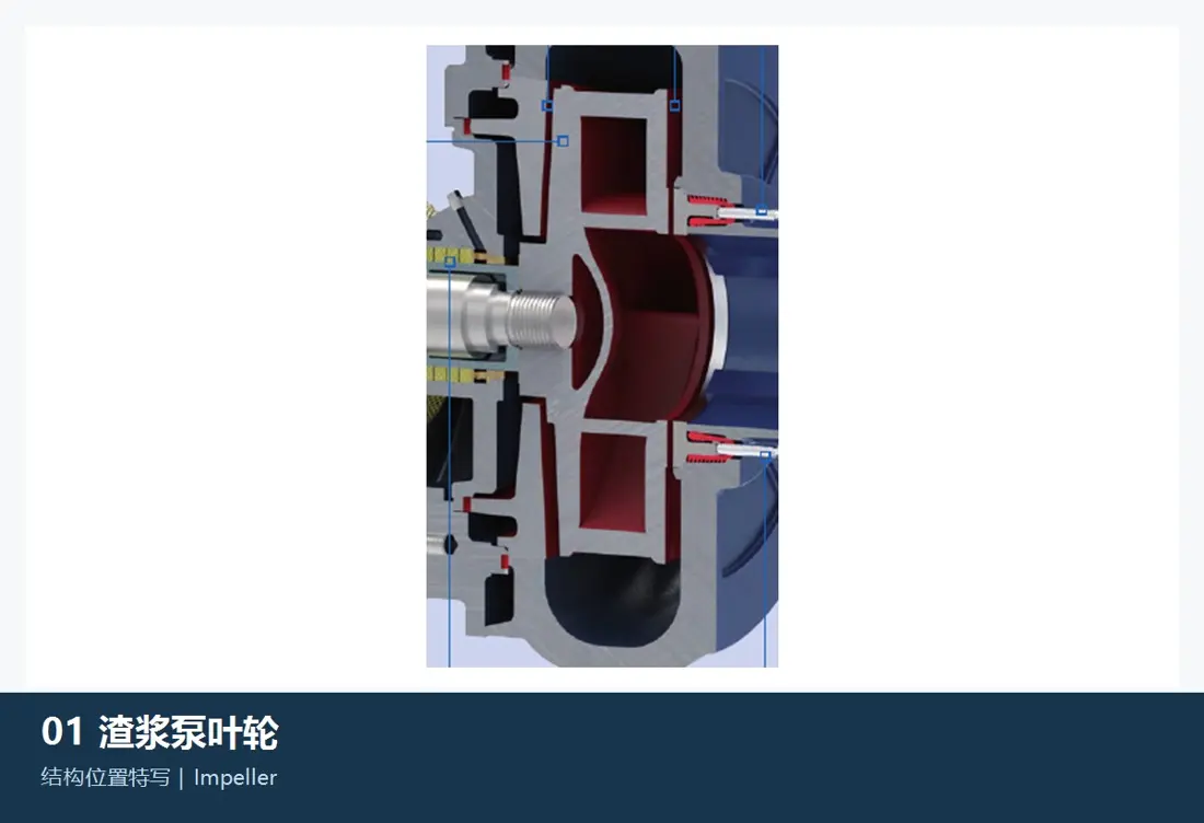
المكون الدوار الرئيسي الملامس للملاط. طابق سلسلة المضخة وحجمها والقطر الخارجي للدافعة وعرضها وعدد الريش والدوران والممرات وفتحة الدخول والوصلة اللولبية أو اتصال العمود ودرجة الاتزان واتجاه التصريف ونقطة التشغيل.
عرض تفاصيل الجزء →حدد سلسلة المضخة وحجمها، ثم راجع الدافعات والأغلفة الحلزونية والبطانات وجلب الحلق والبطانات الأمامية والخلفية وحلقات التآكل القابلة للضبط والأعمدة وأختام الإحكام والمحامل والمواد والرسم وأدوات الصيانة.
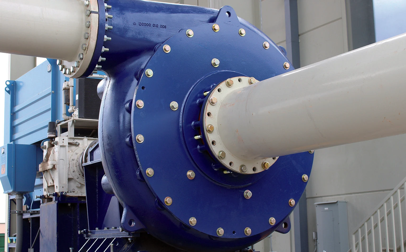
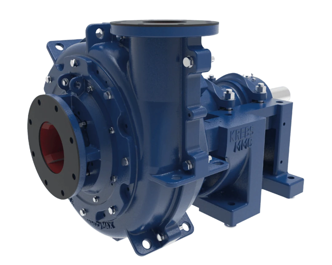
لا يحدد تطابق حجم المضخة قابلية تبادل القطع. قبل التسعير، طابق السلسلة والحجم الكامل واللاحقة وتصنيف الضغط واتجاه الدوران واتجاه التصريف والدافعة والغلاف والبطانات وحلقة التآكل وختم إحكام العمود وهيكل مجموعة الإدارة والرسومات للمضخة نفسها.
ترد الأحجام القياسية في أدلة FLS KREBS الحالية وتساعد على تحديد المعدات. ولا تحل محل الاختيار الهيدروليكي ولا تحدد قابلية تبادل الأجزاء الملامسة للملاط.
| Series | التصميم / الإصدار | الأحجام القياسية أو النطاق | التطبيقات الرئيسية | بيانات تحديد قطع الغيار المطلوبة |
|---|---|---|---|---|
| millMAX | جزء معدني ملامس للملاط للخدمة الشاقة | 3×2, 4×3, 6×4, 8×6, 10×8, 12×10, 14×12, 16×14, 18×16, 20×18, 24×20, 28×26 | تفريغ المطاحن والملاط شديد الكشط؛ حلقة تآكل قابلة للضبط لإحكام جانب الشفط | طابق معا حجم المضخة والدافعة والغلاف وحلقة التآكل والدوران واتجاه التصريف وهيكل مجموعة الإدارة |
| millMAX HP / HH | ضغط عال / ارتفاع ضخ كبير | HP: 14×12, 20×18, 24×20; HH: 3×2, 4×3, 6×4, 8×6, 10×8, 12×10 | تطبيقات متعددة المراحل بضغط عال أو ارتفاع ضخ إجمالي كبير؛ HP مناسب للتطبيقات التي تتجاوز 500 psi (35 bar) | لا تستبدل القطع اعتمادا على حجم millMAX القياسي وحده؛ طابق تصنيف ضغط الغلاف والتصميم متحد المركز أو الحلزوني |
| millMAX-e | مضخة مدمجة وكفؤة للخدمة المتوسطة | 2×1.5, 3×2, 4×3, 6×4, 8×6, 10×8, 12×10, 14×12, 16×14 | رمال معدنية وألومينا واستخلاص وأوساط مخففة ومياه الإحكام وفحم ناعم وفائض المكثف ومياه راجعة من المخلفات | طابق قطر الدافعة وحلقة التآكل والغلاف وختم إحكام العمود وهيكل مجموعة الإدارة وتكوين المحرك |
| slurryMAX | غلاف منقسم للخدمة الشاقة | 3×2, 4×3, 6×4, 8×6, 10×8, 12×10 | بطانات قابلة للاستبدال وخيارات لمواد الدافعة، مع حلقة تآكل قابلة للضبط | طابق السلسلة القياسية / XD / HP / XHP والبطانات والغلاف الخارجي وتصنيف الضغط |
| slurryMAX XD / HP / XHP | غلاف منقسم للخدمة فائقة الشدة / الضغط العالي | XD: من 2×2 إلى 20×18؛ HP: من 4×4 إلى 16×14؛ XHP متاح بحجم 16×14 | خدمة شديدة الكشط وتغذية الهيدروسيكلونات ومخلفات وتطبيقات ضغط عال متعددة المراحل | تختلف XD وHP وXHP في متانة الغلاف؛ طابق مواد الأجزاء الملامسة للملاط وبيانات الطراز باستخدام اللاحقة الكاملة |
| UMD Ultimate Mill Discharge | مضخة تفريغ مطحنة للخدمة الشاقة | 6×5, 8×6, 10×8, 12×10, 14×12, 16×14, 18×16, 20×18, 22×20, 26×22, 28×26, 32×28, 34×32, 38×34 | تفريغ مطاحن الصخور الصلبة؛ نطاق التدفق المنشور 50–20,000 m³/h | طابق الإصدار القياسي / عالي الضغط / المبطن بالكامل بالمطاط والدوران والبطانات ورسومات الأجزاء الملامسة للملاط |
| gravelMAX | مضخة ملاط للجسيمات الكبيرة | طابق مع وثائق الاختيار الخاصة بالمشروع | ممرات واسعة ومناولة جسيمات كبيرة للملاط الكاشط المحتوي على مواد صلبة خشنة | طابق ممرات الدافعة وحجم الجسيمات ومدخل الشفط والغلاف واتجاه التصريف |
| hMAX | مضخة أفقية بدافعة غائرة | طابق مع وثائق الاختيار الخاصة بالمشروع | خدمة تشمل هواء محتبسا أو منتجات حساسة للقص أو أليافا أو جسيمات كبيرة؛ غلاف متحد المركز وخلوصات داخلية كبيرة | تختلف الدافعة الغائرة عن الجزء القياسي الملامس للملاط في millMAX؛ ولا يكفي المظهر وحده لتحديد التوافق |
| vMAX / vMAX-R | مضخة رأسية كابولية | طابق مع وثائق الاختيار الخاصة بالمشروع | أحواض تجميع وملاط مهوى ومناولة مواد صلبة؛ يصل الحد الأقصى المنشور لحجم الجسيمات إلى 56 mm حسب الطراز | طابق عمق الغمر والعمود الرأسي والدافعة والبطانات وترتيب الشفط السفلي وهيكل التركيب |
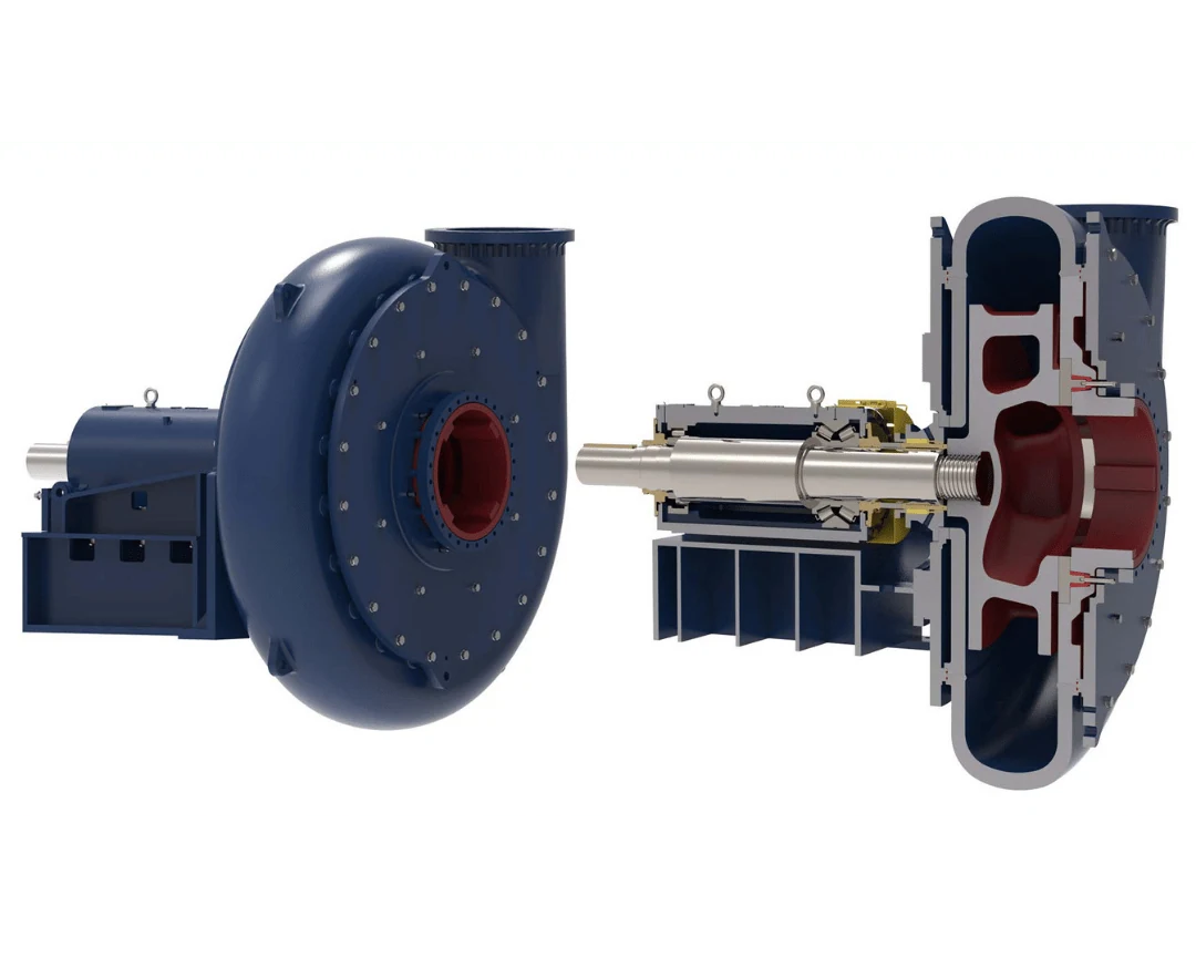
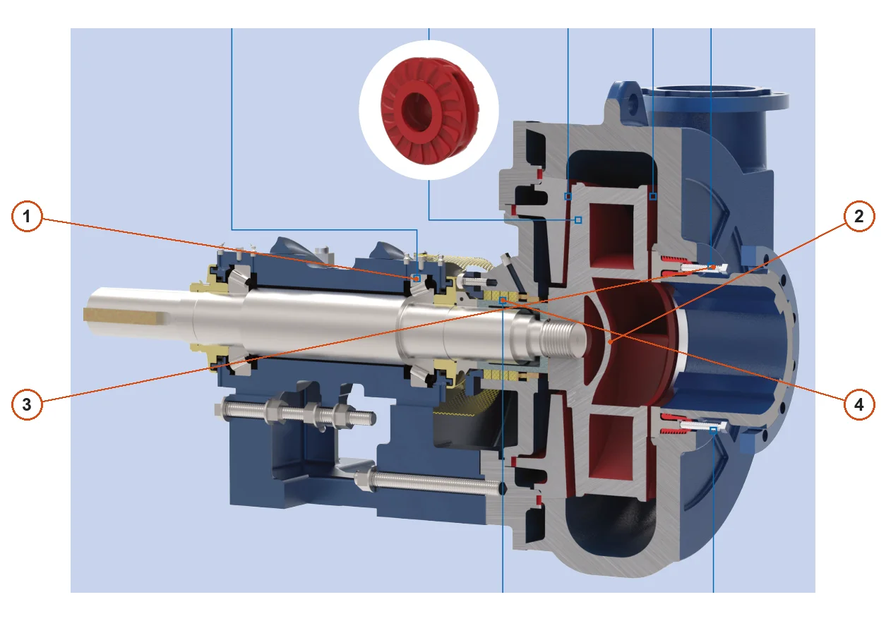
تتطابق الأرقام على المخطط مع الصفوف أدناه.
| الرقم | المكوّن | الموضع | ينطبق على |
|---|---|---|---|
| 1 | محامل دحرجية | مجموعة المحامل حول الجزء الخلفي من عمود المضخة | millMAX |
| 2 | الدفاعة | وسط غلاف المضخة | millMAX |
| 3 | مسامير الضبط الخارجية لحلقة التآكل | ضبط حلقة التآكل من جهة السحب | millMAX |
| 4 | ختم حشوة إحكام بغسل مائي كامل التدفق | منطقة ختم إحكام العمود خلف الدافعة | millMAX |
تتبع مسار الملاط من مدخل الشفط عبر الدافعة إلى المخرج الحلزوني. يرتبط كل مكون بصفحته العامة وصفحة المادة ذات الصلة.
الدفاعة
المكون الدوار الرئيسي الملامس للملاط. طابق سلسلة المضخة وحجمها والقطر الخارجي للدافعة وعرضها وعدد الريش والدوران والممرات وفتحة الدخول والوصلة اللولبية أو اتصال العمود ودرجة الاتزان واتجاه التصريف ونقطة التشغيل.
عرض تفاصيل الجزء →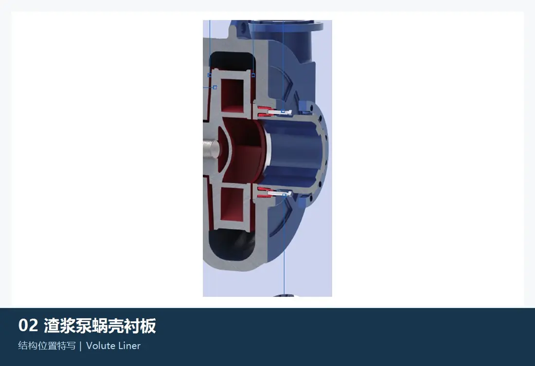
الغلاف الحلزوني / بطانة الغلاف
يحتوي الملاط عالي السرعة الخارج من الدافعة ويشكل ممر التصريف. طابق الغلاف المعدني millMAX أو تصميم الغلاف المنقسم slurryMAX / UMD وحجم المضخة والدوران واتجاه التصريف وتقسيم البطانة والسماكة والشفات.
عرض تفاصيل الجزء →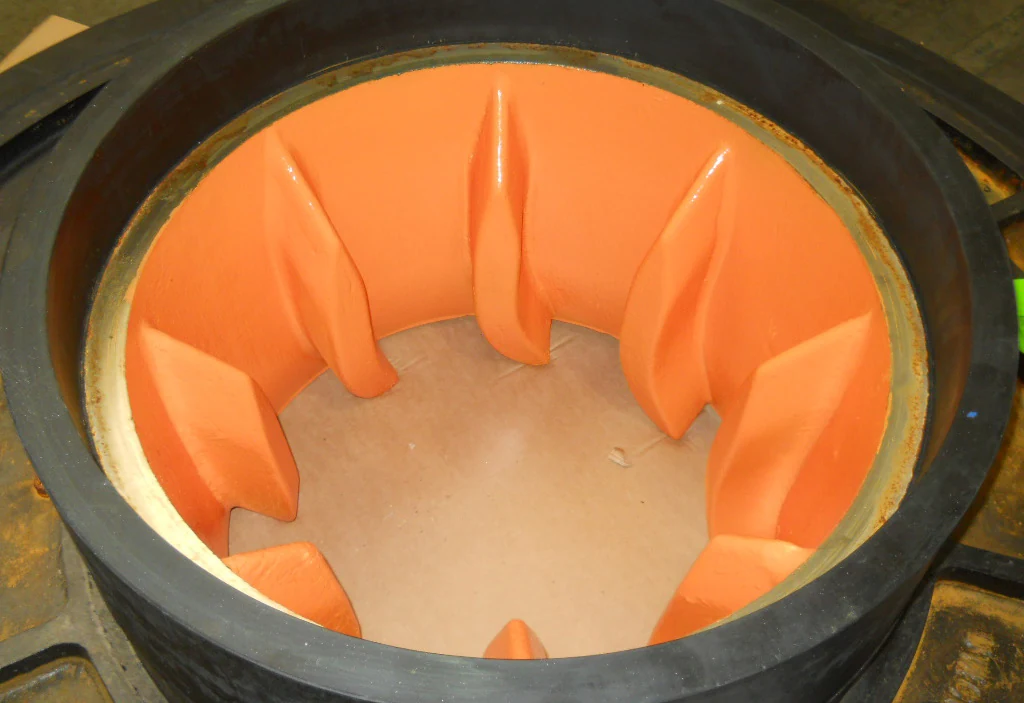
جلبة الحلق / بطانة الشفط
تقع عند مدخل الشفط أمام فتحة دخول الدافعة؛ وتؤثر مع حلقة التآكل القابلة للضبط في خلوص جانب الشفط. طابق حجم المضخة وقطر الفتحة والمقطع وكتف التمركز والسماكة ونمط الثقوب وواجهة حلقة التآكل والخلوص الأمامي للدافعة.
عرض تفاصيل الجزء →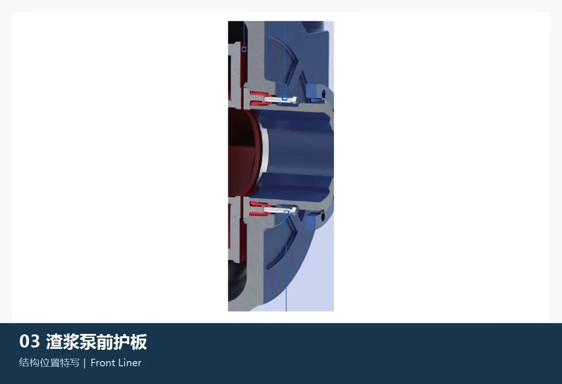
بطانة أمامية / بطانة لوح الهيكل
تحمي غلاف جانب الشفط وتشكل الجزء الملامس للملاط مع جلبة الحلق والدافعة وأسطح الإحكام. طابق السلسلة والحجم والمقطع الداخلي والسماكة ونمط الثقوب ومجاري الإحكام وواجهة حلقة التآكل واتجاه التجميع.
عرض تفاصيل الجزء →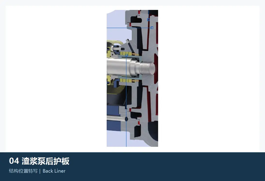
بطانة خلفية / بطانة لوح الغطاء
تقع على جانب نظام الإدارة، وتضبط الخلوص الخلفي للدافعة وتحمي المنطقة القريبة من ختم إحكام العمود. طابق السلسلة والحجم وفتحة العمود والمقطع الداخلي والسماكة وواجهة الإحكام وطريقة التثبيت والخلوص الخلفي.
عرض تفاصيل الجزء →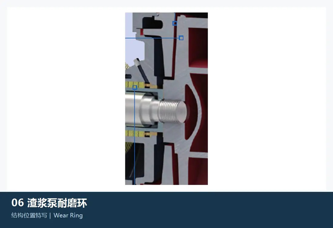
حلقة تآكل / حلقة توزيع الماء
تضبط حلقة التآكل القابلة للضبط في millMAX خلوص جانب الشفط أثناء التشغيل. وتنتمي حلقة توزيع الماء إلى دائرة مياه ختم إحكام العمود. تختلف وظيفتاهما وتصميماتهما، لذا حدد كل واحدة حسب موضعها في التجميع.
عرض تفاصيل الجزء →حدد مكونات نظام الإدارة والإحكام بشكل منفصل، مع التركيز على رموز هيكل مجموعة الإدارة والمحامل وتوافقات العمود والمبيت وترتيب الإحكام والتزييت والمحاذاة مع الجزء الملامس للملاط.
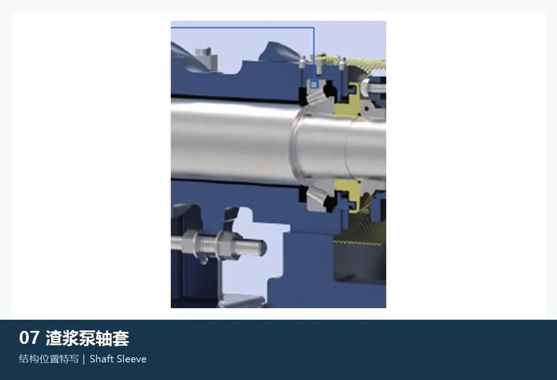
عمود المضخة وجلبة العمود
ينقل عمود المضخة عزم الدوران؛ وتحمي الجلبة منطقة الإحكام. وهما مكونان منفصلان. طابق السلسلة ورمز هيكل مجموعة الإدارة والطول الإجمالي وقطر العمود ومقاعد المحامل والسنون اللولبية والمفاتيح واتصال الدافعة والقطر الداخلي والخارجي للجلبة وأسطح الإحكام والدوران.
عرض تفاصيل الجزء →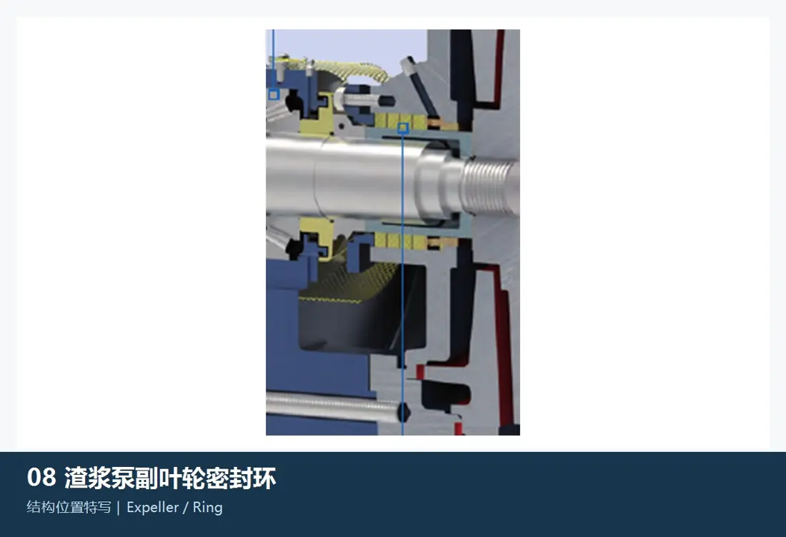
دافعة الطرد وحلقة دافعة الطرد
المكونات الدوارة والثابتة لختم إحكام عمود جاف بالطرد المركزي. طابق حجم المضخة وهيكل مجموعة الإدارة والجلبة والأقطار الداخلية والخارجية والريش والخلوصات والدوران والغلاف والمادة وفرق الضغط المستهدف.
عرض تفاصيل الجزء →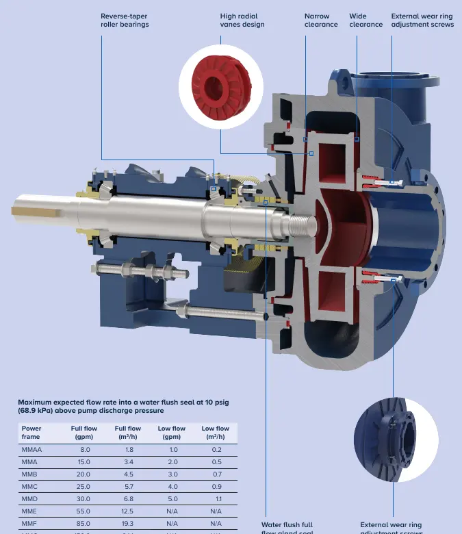
بطانة صندوق الحشو
تقع حيث يمر العمود عبر الغلاف، وتدعم الحشو أو حلقة توزيع الماء أو مكونات الإحكام المرتبطة بها. طابق السلسلة وهيكل مجموعة الإدارة والجلبة والمقطع الداخلي ونمط الثقوب ووصلات مياه الإحكام وضاغط الحشو واتجاه التجميع.
عرض تفاصيل الجزء →حشو الإحكام وضاغط الحشو والختم الميكانيكي
تذكر FLS خيارات إحكام على جانب نظام الإدارة تشمل الغسل بالماء والطرد المركزي والإحكام الميكانيكي. طابق السلسلة والجلبة وصندوق الحشو وضغط مياه الإحكام وتدفقها والسرعة والحرارة والملاط وترتيب الغسل.
عرض تفاصيل الجزء →مجموعة المحامل والمبيت وهيكل مجموعة الإدارة
يدعم العمود ويحافظ على محاذاة الدافعة وحلقة التآكل وأختام الإحكام. طابق رمز هيكل مجموعة الإدارة MMAA–MMG أو السلسلة المعنية ورمز المحمل والخلوص وتوافقات العمود والمبيت والتزييت والأغطية الطرفية وأختام الإحكام وآلية الضبط الخارجية.
عرض تفاصيل الجزء →يعتمد اختيار المادة على صدمات الجسيمات الخشنة والتعرية بالجسيمات الناعمة والتآكل الكيميائي والضغط والسرعة المحيطية للدافعة وظروف الإحكام. ليست السبيكة عالية الكروم الخيار الافتراضي لكل موضع؛ ويجب أن تستوفي الإلاستومرات والبولي يوريثان أيضا حدود التصميم والسرعة والحرارة.
مقاس المضخة وحده لا يحدد قابلية التبادل. قارن السلسلة الكاملة واللاحقة وتصميم الغلاف والبطانات والدافعة وحلقة التآكل وختم العمود والضغط المقنن واتجاه الدوران واتجاه مخرج الطرد وهيكل مجموعة الإدارة والرسومات.
اختر مبدئيا السبائك عالية الكروم أو المطاط الصناعي أو البولي يوريثان أو التقوية الموضعية بطبقة سطحية صلبة حسب موضع الجزء ونمط التلف. ثم طابق الاختيار مع التصميم الأصلي وحجم الجسيمات والتركيز والتآكل الكيميائي والضغط والسرعة والرسومات ومتطلبات القبول.
قدم السلسلة والمقاس الكاملين واللاحقة والرقم التسلسلي واتجاه الدوران واتجاه مخرج الطرد والرسومات أو العينات وصور الأجزاء المتآكلة والمادة والتدفق والرفع والسرعة وظروف الملاط. تساعد هذه المعلومات في تعريف الأجزاء وتقييم المواد وتنسيق التصنيع وضبط الجودة وتسليم الأجزاء النهائية.
أو تواصل معنا مباشرة: +86 156 3797 3199
zzx@anranst.com
تقدّم ANRANST لعملائها حول العالم التقييم الهندسي والإنتاج في مسابك معتمدة وفق المتطلبات الفنية للعميل ومراقبة الجودة وتسليم القطع الجاهزة لقطع التآكل المخصّصة وقطع الغيار الصناعية، مع إمكانية دعم قطع صناعية مخصّصة أخرى.
نراجع أسطح التزاوج وأبعاد الوصلات، ونقيّم إمكانية التصنيع من حيث المادة والمعالجة الحرارية.
Material grades and heat-treatment processes are specified order by order, stated in the technical agreement and tracked through production.
تأكيد الرسم، ومراقبة المواد والعمليات، ومتابعة الإنتاج، والفحص، وتنسيق القبول.
ننسّق التصنيع وتأكيد الجودة والتغليف والتسليم للقطع الكاملة ضمن سلسلة توريد متكاملة وعملية.
Provide the equipment brand, complete model and serial number, part name, part number or drawing number, drawing revision, quantity, material requirements and duty. If identifiers are unavailable, send photographs and key dimensions.
أرسل استفساراً