FLS PAF / RKF Heavy-Duty Apron Feeders

Start with the current design range and documented RKF configurations to identify pans, liners, chains, chain pins and bushings, rollers, sprockets and tensioners, then confirm materials and drawing numbers for a quotation.

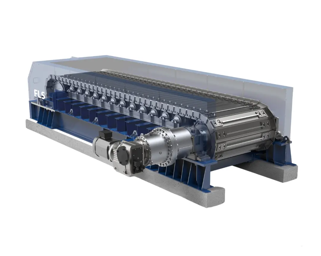
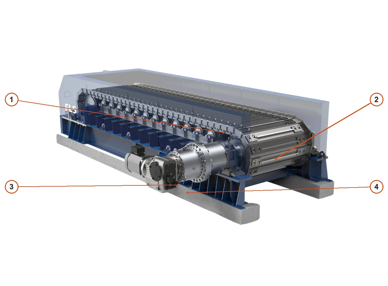
Official FLS heavy-duty apron feeder cutaway structure
Official FLS structural image of the current heavy-duty apron feeder, showing pans, track chains, support rollers, sprockets, drive and tensioning positions.
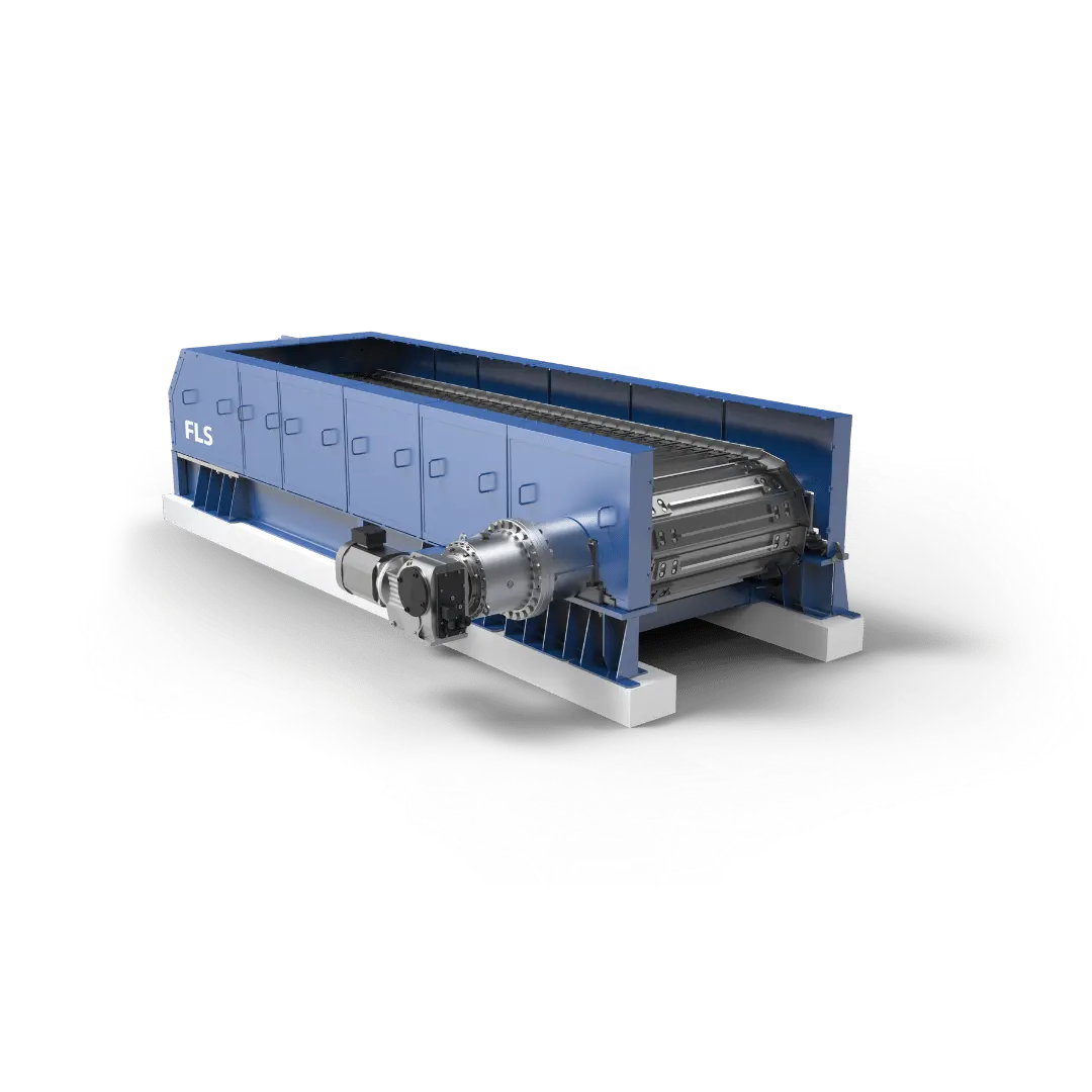
Official FLS heavy-duty apron feeder machine image
Official FLS image of the current heavy-duty apron feeder, clearly showing the upper skirts, receiving area and head drive structure.
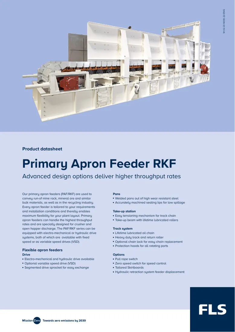
First page of the official FLS Primary Apron Feeder RKF datasheet
First page of the official FLS Primary Apron Feeder RKF datasheet. Use this document for the model range, structural options and core parameters.
OEM Equipment Details

Configurations, wear parts, drive spares and materials on one page

PAF / RKF heavy-duty apron feeders are customized to project conditions. This page provides design ranges, official configuration examples, installation positions, material selection, drawing checks and an enquiry route to help confirm spares against the installed equipment records.

1 Current published design range
2 Official configuration examples
6 Wear parts
5 Core spares
Current design range

PAF / RKF key dimensions and drive range

This product is customized to project feed conditions, capacity, installation space and downstream interfaces. The table lists only ranges explicitly stated in the current public FLS datasheet.

SeriesPan widthEquipment lengthChain sizeMaximum feed sizeMaximum inclinationMaximum speedDrive power
Primary Apron Feeder PAF / RKF1.0–3.0 mUp to 30 mD4–D10Up to 2,000 mmUp to 26°Up to 30 m/min45 kW–2 × 700 kW

Actual capacity also depends on bulk density, maximum lump size, hopper pressure, inclination, speed, pan structure, drive type and downstream interfaces. Width or length alone is insufficient to identify spares.

Official brochure configurations

Documented RKF project configuration examples

These two examples come from the official FLS product brochure and support identification of historical installations. They are not a complete list of current configurations.

Configuration designationWidthLengthChain sizeChain arrangementDocument status
RKF 2.2 × 15.8 - D82.2 m15.8 mD8Inboard chainsProject configuration example in the official FLS product brochure
RKF 3.4 × 17.0 - D93.4 m17.0 mD9Outboard chainsProject configuration example in the official FLS product brochure
Wear Parts

Pans, impact plates and liners by position

Start with pans directly exposed to ore impact and abrasion, then review receiving, sidewall, tail, head discharge and drip pan positions. Each item links to the relevant part and material pages.

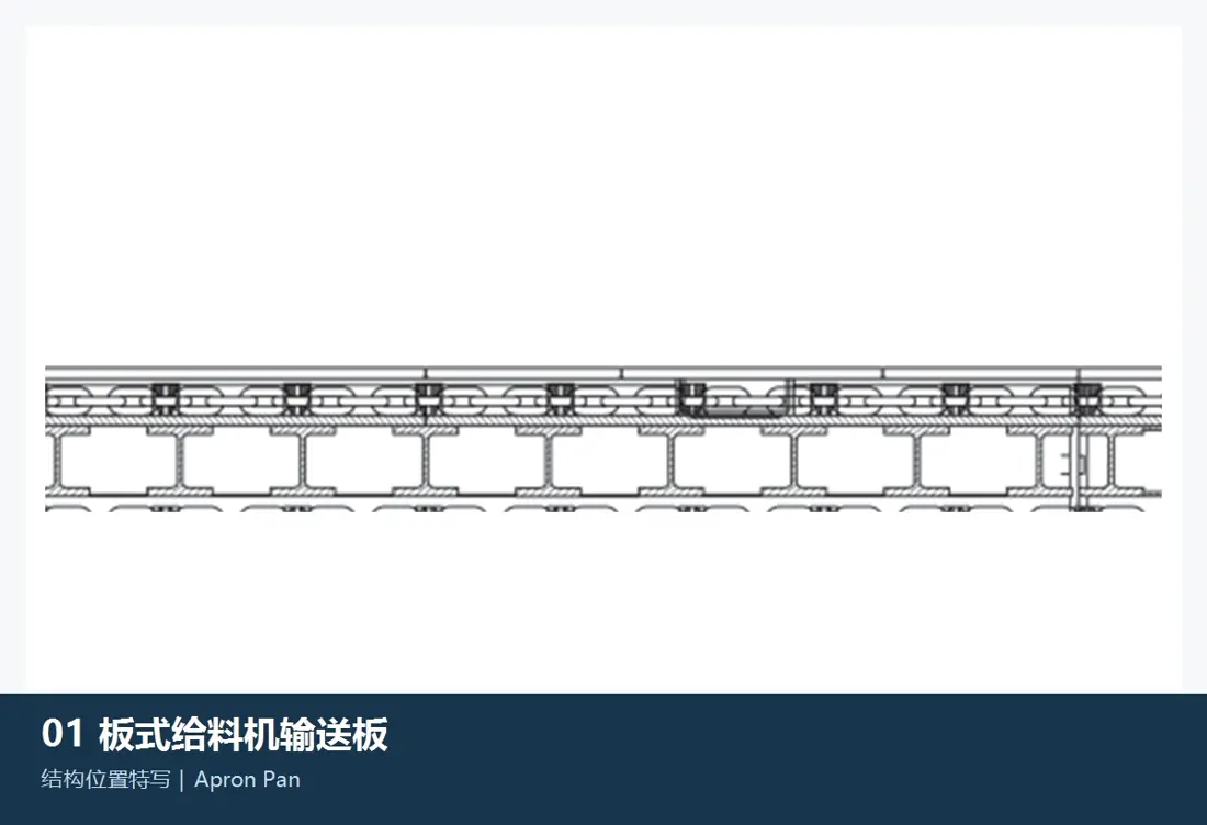
Pan position reference in the FLS PAF RKF apron feeder structure
01

Apron Pans / Feeder Pans

Apron Pan / Feeder Pan

Pans receive large rocks and circulate with the chains, making them a principal impact and abrasion component. Check pan width, pitch, thickness, overlap direction, ribs, connecting holes, chain mounting distance and the head/tail wheel clearance envelope.

Material and manufacturing checks:Confirm manganese steel pans, fabricated wear-steel pans or wear-resistant cast steel against drop height, lump size, impact and wear conditions. Use the drawings for grade, heat treatment and plate thickness.

View Part Details →
Receiving impact plate position reference in the FLS PAF RKF apron feeder
02

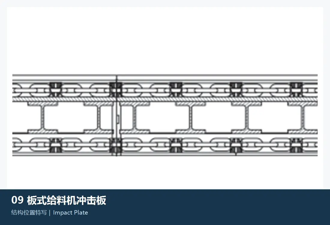
Receiving Impact Plates

Impact Plate

Installed in high-drop receiving zones, these plates distribute direct impact from large lumps on pans, supports and frames. Check installation section, plate shape, thickness, hole pattern, fastening structure, material drop point and safe clearance to pans.

Material and manufacturing checks:Select quenched and tempered wear plate, bimetallic composite plate or wear-resistant cast steel according to impact energy, abrasive particle hardness and replaceable construction.

View Part Details →
Side and skirt liner position reference in the FLS PAF RKF apron feeder
03

Side Liners / Skirt Liners

Side Liner / Skirt Liner

These liners protect the hopper or skirt sides and contain material flow. Check left/right side, segment order, plate thickness, hole pattern, overlaps, pan clearance, material bed height and leakage paths.

Material and manufacturing checks:Confirm quenched and tempered wear plate, bimetallic composite plate or wear-resistant cast steel according to sliding wear, localized impact and plate stiffness.

View Part Details →
Tail inlet liner position reference in the FLS PAF RKF apron feeder
04

Tail Inlet Liners

Tail / Inlet Liner

These liners protect the tail inlet and hopper transition. Check feed direction, installation side, liner profile, plate thickness, hole pattern, overlaps with adjacent liners and clearance to returning pans.

Material and manufacturing checks:Confirm wear plate, bimetallic composite plate or wear-resistant cast steel according to falling-material impact, blockage risk and wear distribution.

View Part Details →
Head discharge chute liner position reference in the FLS PAF RKF apron feeder
05

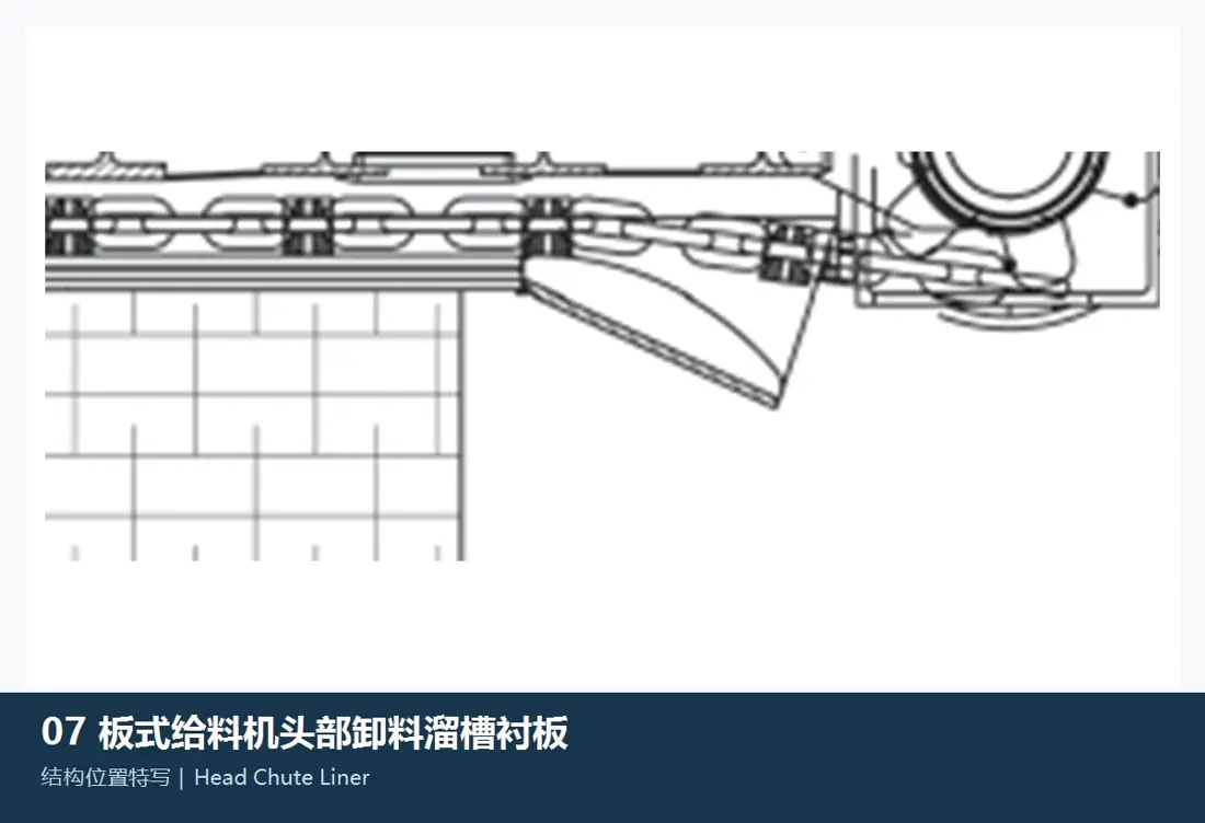
Head Discharge Chute Liners

Head Discharge Chute Liner

These liners protect the head discharge area and changes of direction in downstream chutes. Check discharge trajectory, mounting face, segment layout, plate thickness, hole pattern, adjacent structural clearances and downstream equipment interfaces.

Material and manufacturing checks:Confirm quenched and tempered wear plate, bimetallic composite plate or wear-resistant cast steel according to impingement angle, velocity, material hardness and replacement interval.

View Part Details →
Drip pan liner position reference in the FLS PAF RKF apron feeder
06

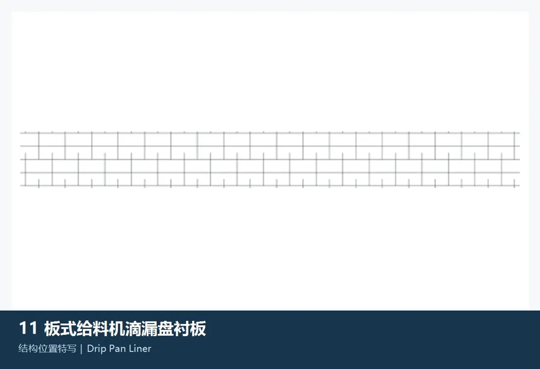
Drip Pan Liners

Drip Pan Liner

These liners protect the collection pan below the return chain from accumulated fines, dragging and cleaning wear. Check segment length, width, plate thickness, hole pattern, cleaning direction and clearance to return components.

Material and manufacturing checks:Confirm wear plate or engineering polymer liners according to fines wear, noise, friction and cleaning method. Do not assume the same material as the main receiving pans.

View Part Details →
Spare Parts

Chains, pins, bushings, rollers, sprockets and tensioners

Parts with the same name are not interchangeable by appearance across RKF configurations, chain sizes, inboard/outboard arrangements or installation sides. Check dimensional relationships, materials and function.

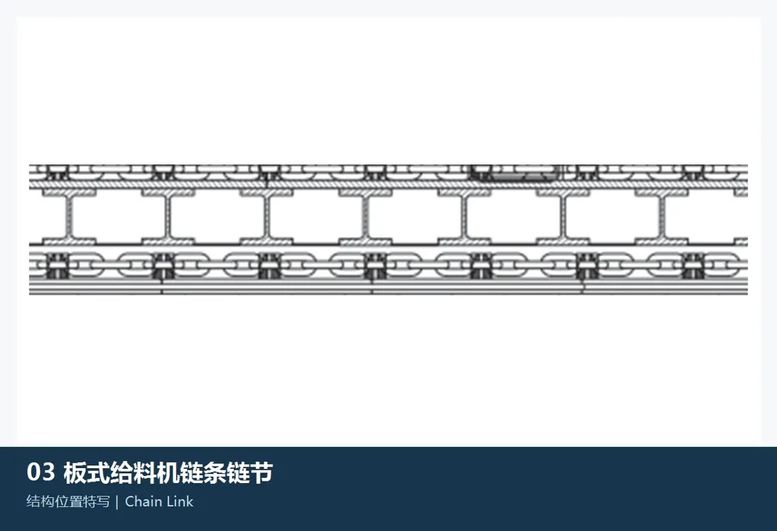
Track chain link position reference in the FLS PAF RKF apron feeder
01

Track Chain Links

Track Chain Link

Links transmit traction with pins, bushings and pan connectors. Check FLS chain size D4–D10, inboard or outboard arrangement, pitch, track width, mounting distance, connecting holes and lubrication type.

Material and manufacturing checks:Confirm track chain alloy steel, surface/through heat treatment and mating hardness according to traction loads, impact, speed and sealed-for-life lubrication design.

View Part Details →
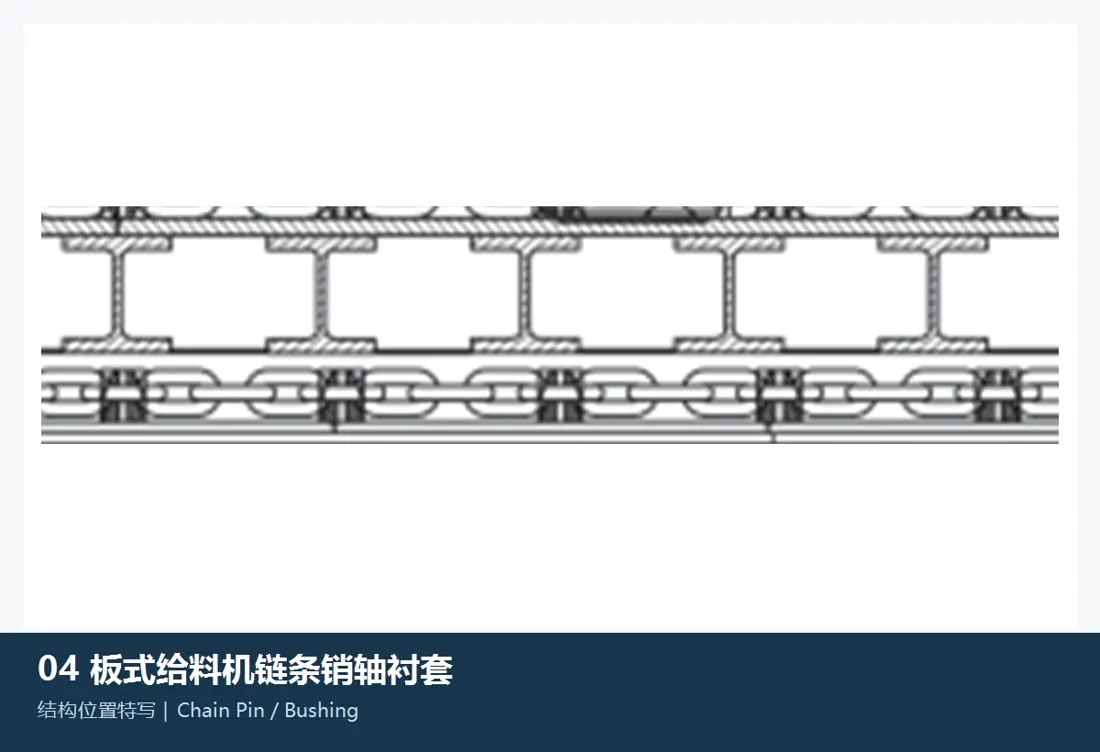
Chain pin and bushing position reference in the FLS PAF RKF apron feeder
02

Chain Pins and Bushings

Chain Pin and Bushing

Pins and bushings form chain joints and withstand alternating bearing pressure. Check pin and bushing diameters, length, interference, end retention, lubrication structure, link model and mating clearance.

Material and manufacturing checks:Confirm carburized or quenched and tempered alloy steel, hardened depth, core toughness and surface roughness against the original chain design.

View Part Details →
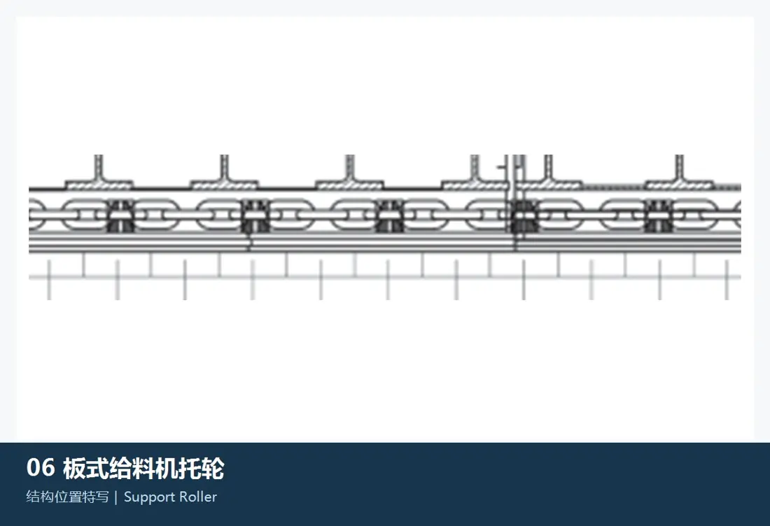
Load and return roller position reference in the FLS PAF RKF apron feeder
03

Load Rollers / Return Rollers

Track and Return Roller

These rollers support loaded track chains and return chains, maintaining their running path. Check roller diameter and width, shaft diameter, mounting distance, bearings, seals, lubrication, load/return side and frame interfaces.

Material and manufacturing checks:Confirm forged or cast alloy steel roller bodies, bearing steel and seal materials according to load, dust, temperature and lubrication conditions.

View Part Details →
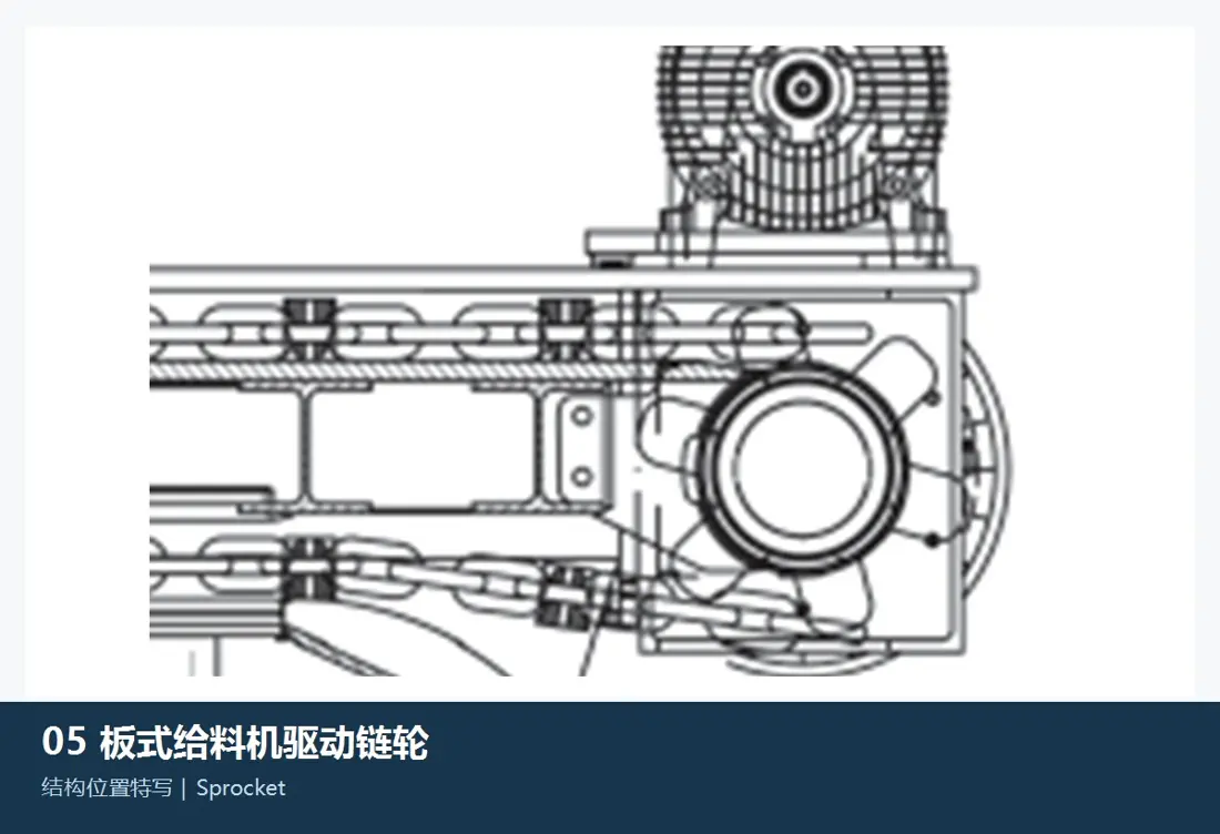
Drive sprocket and tooth segment position reference in the FLS PAF RKF apron feeder
04

Drive Sprockets / Segmented Teeth

Drive Sprocket / Tooth Segment

Sprockets mesh with the track chains to transmit drive torque. The current FLS design uses replaceable bolted tooth segments. Check tooth count, pitch, tooth profile, installation side, hub, hole pattern, shaft fit and chain size.

Material and manufacturing checks:Confirm forged or cast transmission alloy steel, tooth surface heat treatment and mating track chain hardness according to torque, impact and required meshing life.

View Part Details →
Hydraulically assisted tensioner position reference in the FLS PAF RKF apron feeder
05

Hydraulically Assisted Tensioners

Hydraulic-assisted Take-up

These devices adjust chain tension and compensate for track chain wear. Check travel, thrust, left/right side, slide, cylinder, pins, guides, stops and actual chain elongation.

Material and manufacturing checks:Confirm quenched and tempered alloy steel load-bearing parts, hydraulic cylinder materials and oil-resistant seals according to tensioning force, dust, temperature and maintenance interval.

View Part Details →
Drawing and spare part numbers

Match OEM or third-party numbers to configurations, positions and critical dimensions

When submitting a number, include the complete RKF configuration, serial number, chain size, inboard/outboard arrangement, part name, drawings, used-part photos, critical dimensions, material and operating conditions.

Does FLS PAF / RKF have a fixed set of standard models?

Current documents define it as a heavy-duty apron feeder customized to project conditions. Published data cover width, length, chain, inclination, speed and power ranges. Identify documented configurations through project records.

Can pans and chains be manufactured using equipment width alone?

No. Also check the complete configuration, serial number, chain size, inboard/outboard arrangement, pitch, mounting distance, pan overlaps, hole patterns, drawing number, drawing revision and actual operating conditions.

Submit your FLS PAF / RKF configuration, drawing number, pan or core spare requirements

Provide the complete configuration, serial number, chain size, inboard/outboard arrangement, OEM/third-party number, drawings, used-part photos, critical dimensions, material and operating conditions. We use these to identify parts, assess materials, match manufacturing requirements, control quality and deliver finished components.

Manufacturing Services in China

From Technical Assessment to Finished-Part Delivery

ANRANST provides customers worldwide with engineering assessment, production at certified foundries to drawing, quality control and finished-part delivery for custom wear parts and industrial spares, with scope to support other custom industrial parts.

01

Drawing and Engineering Review

We review mating surfaces and interface dimensions and assess material, heat treatment and manufacturing feasibility.

02

Material and Heat-Treatment Specification

Material grades and heat-treatment processes are specified order by order, confirmed in the technical agreement and tracked through production.

03

Quality Control

Drawing confirmation, material and process control, production tracking, inspection and acceptance coordination.

04

Finished-Part Delivery

We coordinate manufacturing, quality confirmation, packaging and delivery of complete finished parts in a workable, closed-loop supply process.

Provide the existing model, drawings, drawing or part numbers, materials or operating conditions so we can identify the appropriate technical review and supply route.

Submit an Enquiry