FLS KREBS gMAX Hydrocyclones

Start with standard gMAX models and key dimensions to identify inlet heads, cylinder and compound cone liners, vortex finders, spigots, housings and cyclone clusters, then confirm materials and drawing for an enquiry.

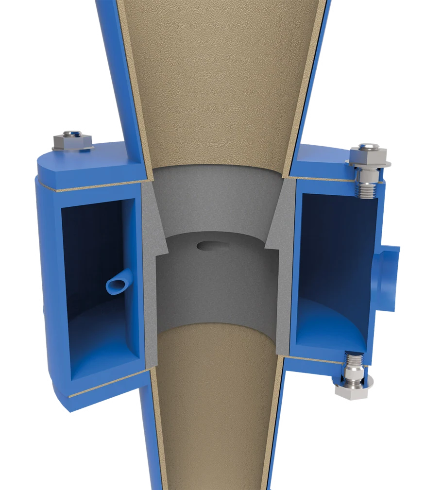
Official FLS KREBS gMAX hydrocyclone product image
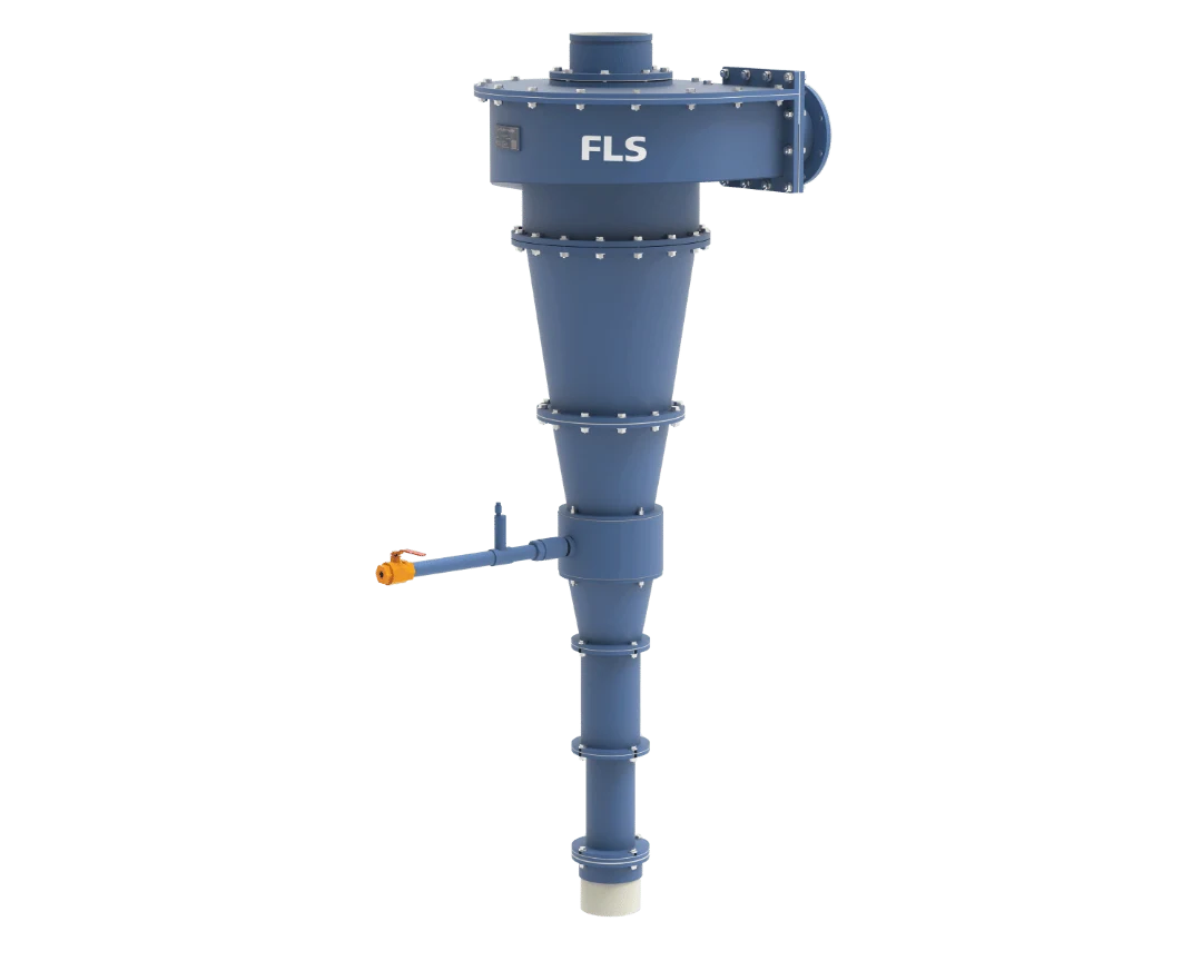
Official FLS KREBS gMAX product image, showing the inlet head, cylinder, segmented cone, overflow and underflow outlets.
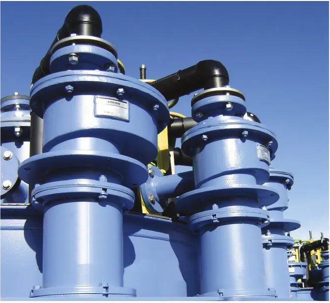
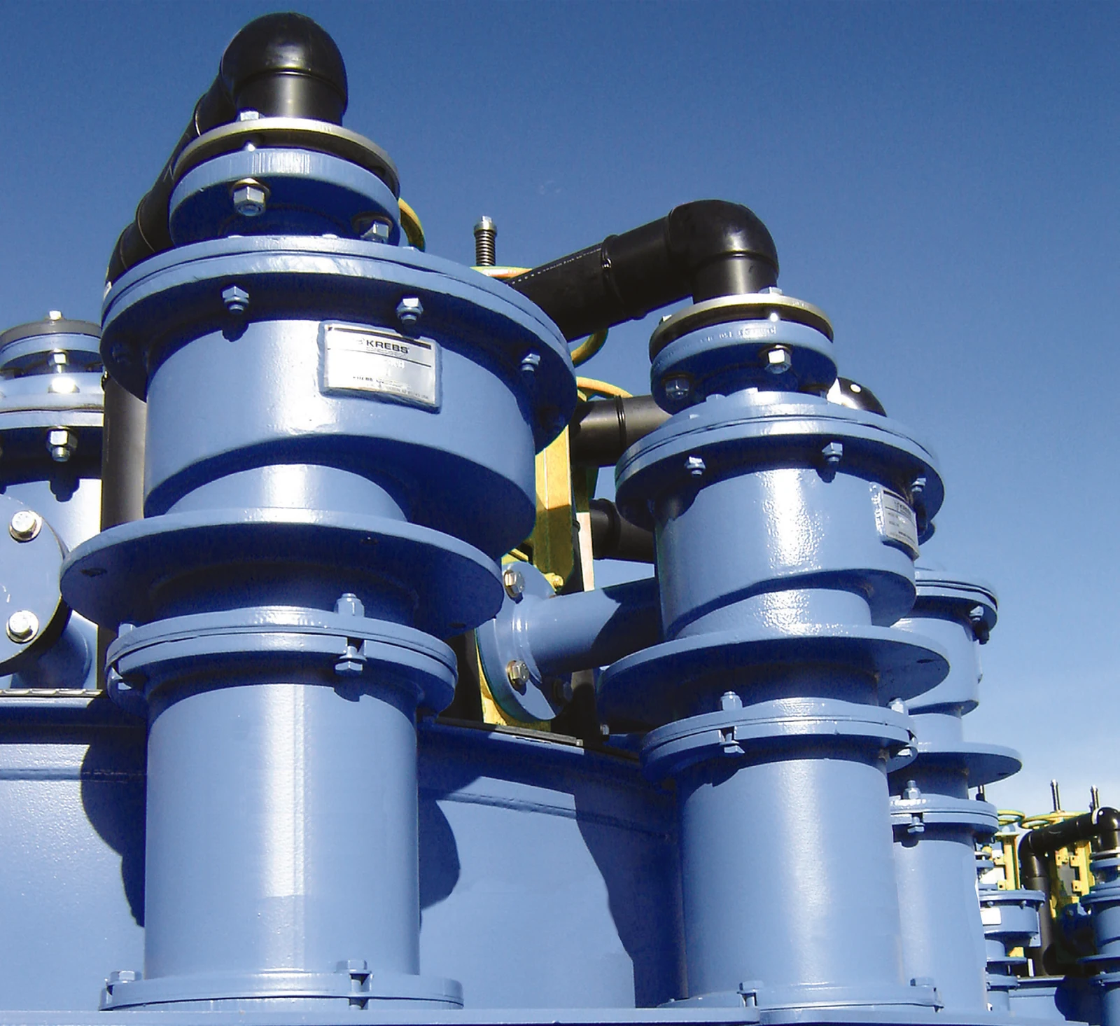
Official FLS KREBS gMAX hydrocyclone installation photo
gMAX installation photo from the official FLS brochure, showing units, upper piping and cyclone cluster connections.
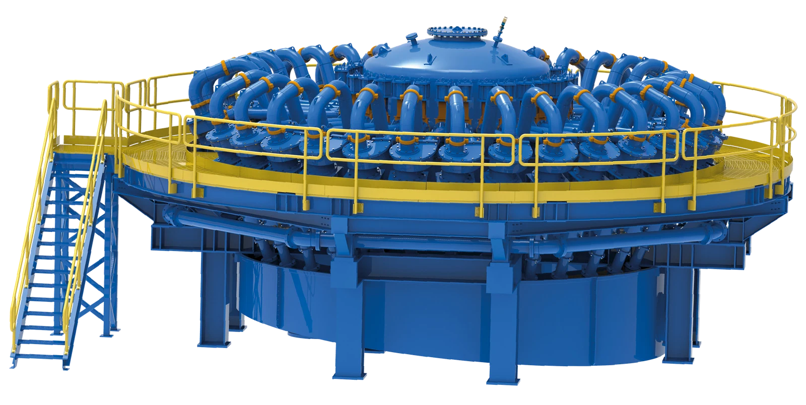
Official FLS KREBS gMAX multi-unit cyclone cluster photo
Multi-unit cyclone cluster in the official FLS brochure, showing manifolds, isolation valves, supports and site layout.
OEM Equipment Details

Models, wear liners, structural spares and materials on one page

gMAX classifies material through the combined geometry of the inlet head, cylinder, compound cone sections and underflow outlet. Before quotation, match the full model, diameter, cone arrangement, vortex finder, spigot, liner material, serial number and drawings to the same unit.

9Verified series/model entries
8Wear parts
4Structural spares
4OEM documentation
Models and key dimensions

gMAX series and standard molded polyurethane models

Diameters and capacities come from the official FLS KREBS brochure. Published capacities at 10–30 psi support model identification only. Actual selection and spares require the individual installation records.

Series / modelStandard diameter / structurePublished capacityApplication and document statusRequired spare identification
gMAX HydrocyclonesMetal housing / replaceable liner seriesProject-specific combination of diameter, inlet, cylinder, cone angle, vortex finder and spigotMineral processing, oil sands, power generation, chemicals, industrial manufacturing and water treatmentConfirm parts against the full model, serial number, structural configuration and drawing revision
U0.513 mm (0.5 in)0.2–0.3 m³/hMolded polyurethane cyclone capacity range at 10–30 psiCheck flow passages, interfaces, configuration and installation parts list
gMAX1U25 mm (1 in)0.7–1.1 m³/hMolded polyurethane gMAX modelCheck inlet, overflow, underflow and manifold interfaces
U2-gMAX51 mm (2 in)1.7–5.5 m³/hMolded polyurethane gMAX modelCheck inlet, overflow, underflow and manifold interfaces
U3-gMAX76 mm (3 in)3.2–12.5 m³/hMolded polyurethane gMAX modelCheck inlet, overflow, underflow and manifold interfaces
gMAX4U102 mm (4 in)5.4–17.3 m³/hMolded polyurethane gMAX modelCheck inlet, overflow, underflow and manifold interfaces
gMAX6U152 mm (6 in)13–33 m³/hMolded polyurethane gMAX modelCheck inlet, overflow, underflow and manifold interfaces
gMAX10U254 mm (10 in)22–114 m³/hMolded polyurethane gMAX modelCheck inlet, overflow, underflow and manifold interfaces
gMAX15U381 mm (15 in)114–273 m³/hMolded polyurethane gMAX modelCheck inlet, overflow, underflow and manifold interfaces
FLS

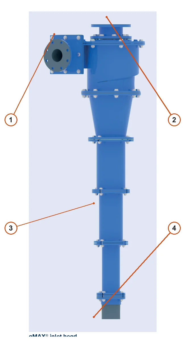
Component Location Diagram

The numbers on the diagram correspond one to one with the rows below.

FLS KREBS gMAX Hydrocyclones – Component Location Diagram
No.ComponentLocationApplies to
1Tangential feed inletSide of the inlet headKREBS gMAX
2Overflow outletTop of the inlet headKREBS gMAX
3Cone sectionsSegmented cone below the inlet headKREBS gMAX
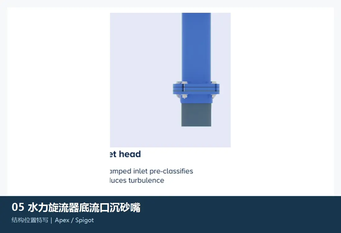
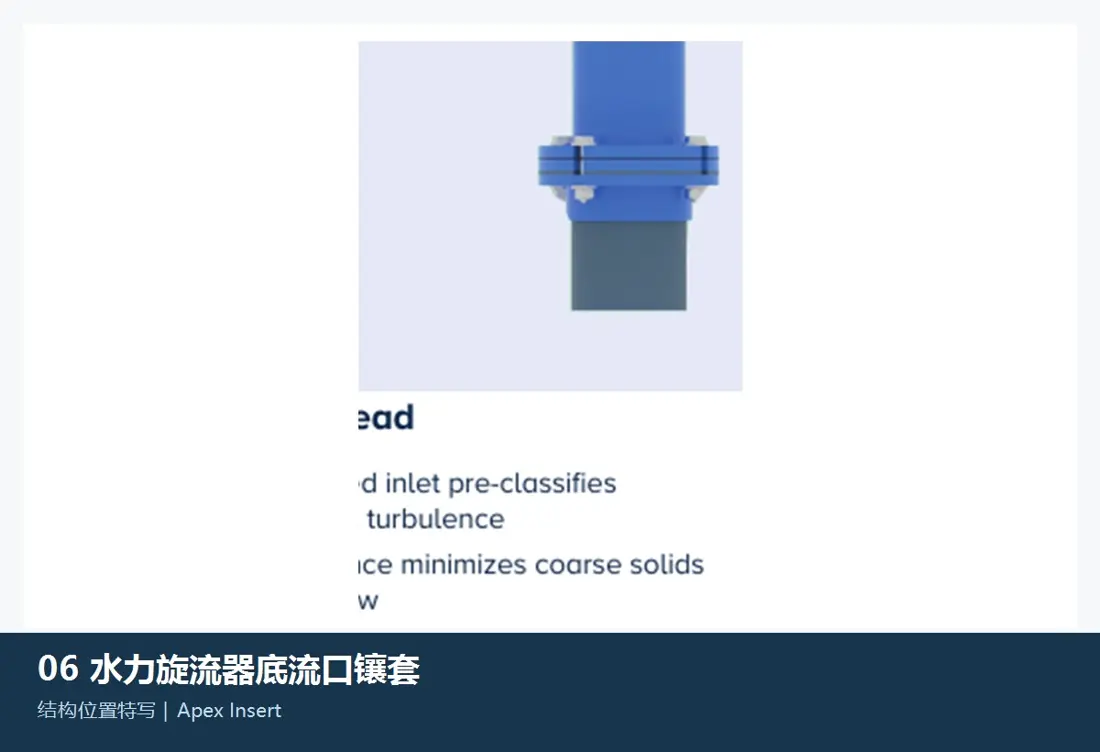
4Underflow outletDischarge at the bottomKREBS gMAX
Wear Parts

Inlet heads, cylinders, compound cones, vortex finders and spigots

Follow the slurry through entry, pre-classification, cylindrical swirling flow, cone classification, overflow and underflow. Each item links to the relevant part and material pages.

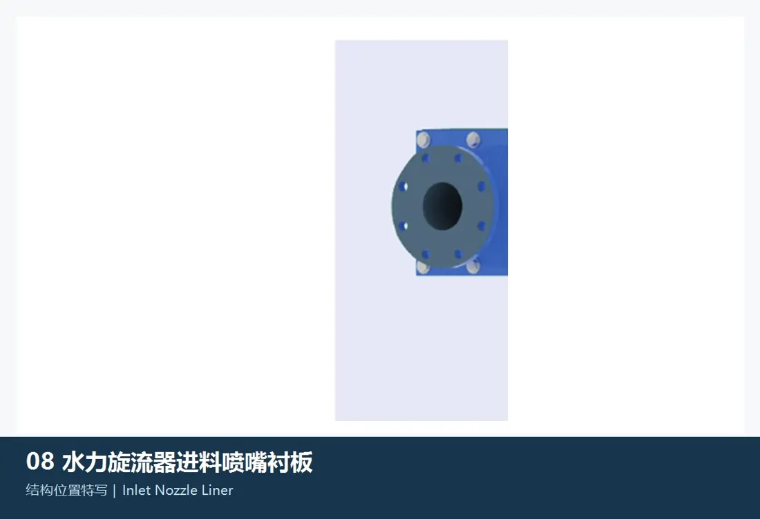
Inlet head and feed chamber liner positions in the FLS KREBS gMAX
01

Inlet Head / Feed Chamber Liners

Inlet Head / Feed Chamber Liner

These liners face high-velocity slurry erosion and particle impact in the tangential inlet and pre-classification zone. Check the full gMAX model, inlet direction and size, internal profile, liner segments, thickness, hole pattern, seals and adjacent cylinder interfaces.

View Part Details →
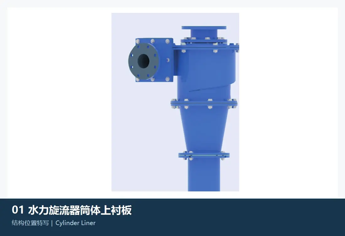
Cylinder and upper liner positions in the FLS KREBS gMAX
03

Cylinder Liners / Upper Liners

Cylinder Liner / Upper Liner

These protect the cylinder below the inlet head and maintain its critical inside diameter. Check cylinder diameter, section count, liner inside/outside diameters, length, flanges, hole patterns, joints, locating shoulders, swirl direction and inlet head position.

View Part Details →
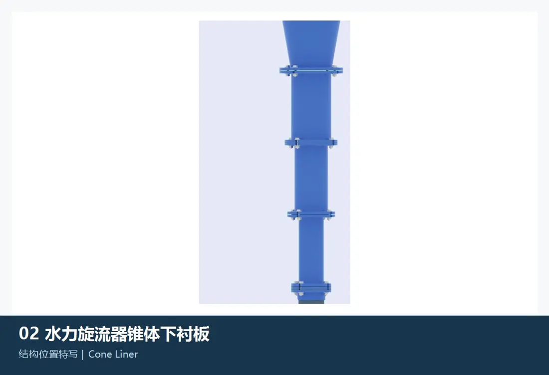
Upper and lower cone liner positions in the FLS KREBS gMAX
04

Upper and Lower Cone Liners

Upper and Lower Cone Liners

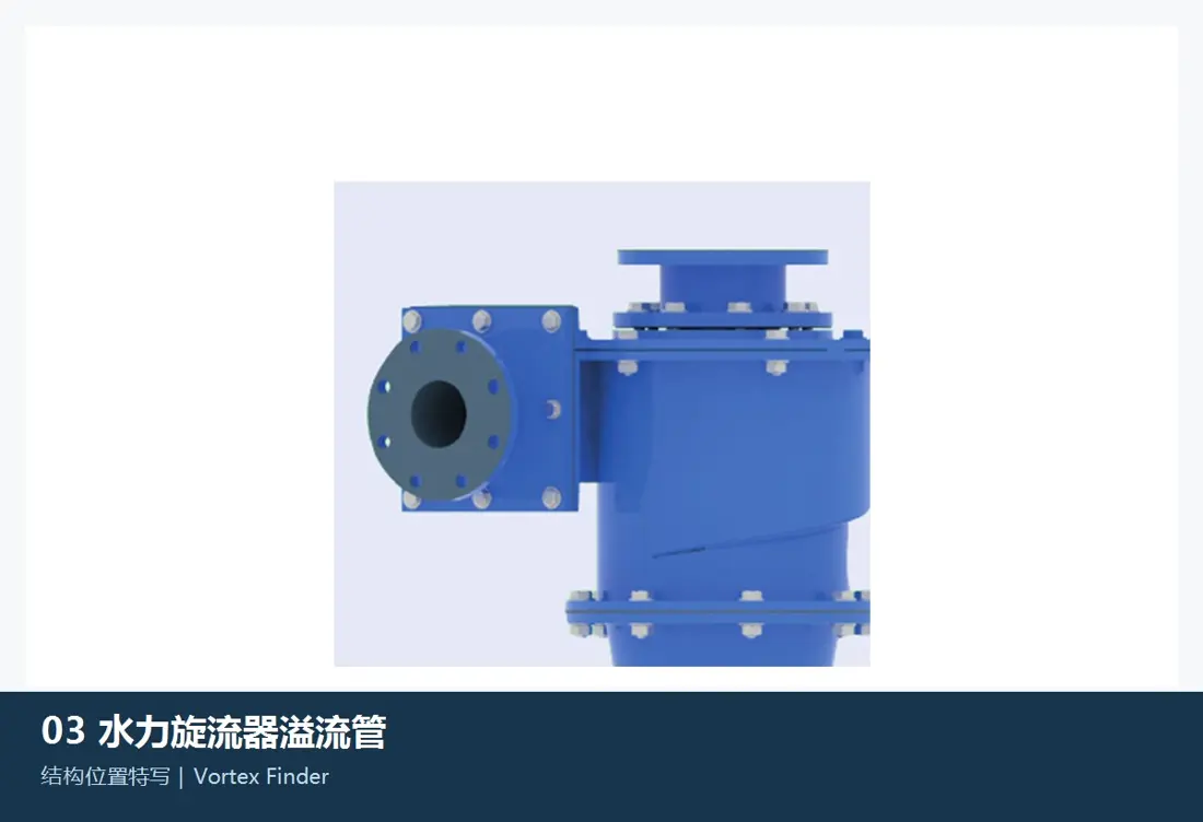
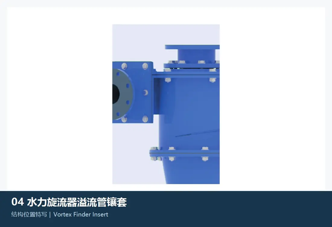
The gMAX compound cone liners determine the classification flow field and face increasingly concentrated abrasion. Check each cone's angle, length, large/small end diameters, flange, sequence, liner thickness, joints and transition to the underflow outlet.

View Part Details →
Spare Parts

Inlet head housings, cylinder sections, cone housings and cyclone clusters

Hydrocyclones have no mechanical drive parts. This section covers structural spares directly related to pressure boundaries, liner support, manifolds, valves, seals and site installation.

Inlet head housing position in the FLS KREBS gMAX
01

Inlet Head Housings

Inlet Head Body

These support the inlet, top cover, vortex finder and cylinder interfaces. Check housing material, inlet direction, flange standard, hole pattern, pressure rating, top cover, liner cavity dimensions and lifting positions.

View Part Details →
Cylinder section and connecting ring positions in the FLS KREBS gMAX
02

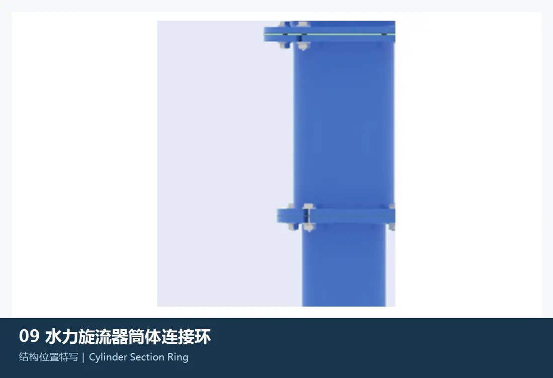
Cylinder Sections and Connecting Rings

Cylinder Section and Ring

These form the pressure boundary and liner support between the inlet head and cones. Check diameter, section length, flanges, hole spacing, seal grooves, housing thickness, connecting rings, liner cavity and adjacent section orientation.

View Part Details →
Cone housing assembly position in the FLS KREBS gMAX
03

Cone Housing Assemblies

Cone Section Body Assembly

Multi-section cone housings must retain the correct sequence, cone angles and flow continuity. Check each section's large/small end diameters, length, flanges, hole patterns, housing material, liner space, seals and supports.

View Part Details →
OEM material range

Confirm liner materials separately from unlined housing materials

The FLS gMAX brochure lists BPC rubber, neoprene, nitrile rubber, chlorobutyl rubber, alumina, nitride-bonded silicon carbide, reaction-bonded silicon carbide and sintered α silicon carbide liners. Unlined housings include 304L/316L, Duplex 2205, CD4MCU, Monel, Inconel, Nickel, Hastelloy, other metal alloys and polyurethane. A material name alone is not a manufacturing specification: installation position, pressure, abrasion, corrosion and original structure must also be confirmed.

FAQ

Frequently asked questions

Is gMAX diameter alone enough to identify liners and spigots?

No. Also check the full model, inlet head, cylinder, cone arrangement, vortex finder, spigot bore, housing and liner materials, serial number and drawing revision.

How are gMAX liner materials selected?

Screen rubber, polyurethane, alumina, silicon carbide ceramics and corrosion-resistant alloys by installation position and failure mode, then confirm against original structure, operating conditions, dimensions, drawings and acceptance requirements.

Submit FLS KREBS gMAX models, drawing, liners or structural spare requirements

Provide the full model, serial number, inlet direction, cyclone diameter, cone arrangement, vortex finder, spigot bore, drawings or samples, used-part photos, material and operating conditions. We use these to identify parts, assess materials, match manufacturing requirements, control quality and deliver finished components.

Equipment Brand and ModelDrawingDrawing or DimensionsCurrent MaterialPhotographs of Failed PartsTarget Service LifeOperating Conditions
Request a Quote

Or contact us directly: +86 156 3797 3199
zzx@anranst.com

Manufacturing Services in China

From Technical Assessment to Finished-Part Delivery

ANRANST provides customers worldwide with engineering assessment, production at certified foundries to the customer technical requirements, quality control and finished-part delivery for custom wear parts and industrial spares, with scope to support other custom industrial parts.

01

Drawing and Engineering Review

We review mating surfaces and interface dimensions and assess material, heat treatment and manufacturing feasibility.

02

Material and Heat-Treatment Specification

Material grades and heat-treatment processes are specified order by order, stated in the technical agreement and tracked through production.

03

Quality Control

Drawing confirmation, material and process control, production tracking, inspection and acceptance coordination.

04

Finished-Part Delivery

We coordinate manufacturing, quality confirmation, packaging and delivery of complete finished parts in a workable, closed-loop supply process.

Provide the equipment brand, complete model and serial number, part name, part number or drawing number, drawing revision, quantity, material requirements and duty. If identifiers are unavailable, send photographs and key dimensions.

Submit an Enquiry