FLS أعاصير KREBS gMAX المائية

Start with standard gMAX models and key dimensions to identify inlet heads, cylinder and compound cone liners, vortex finders, spigots, housings and cyclone clusters, then confirm materials and drawing numbers for an enquiry.

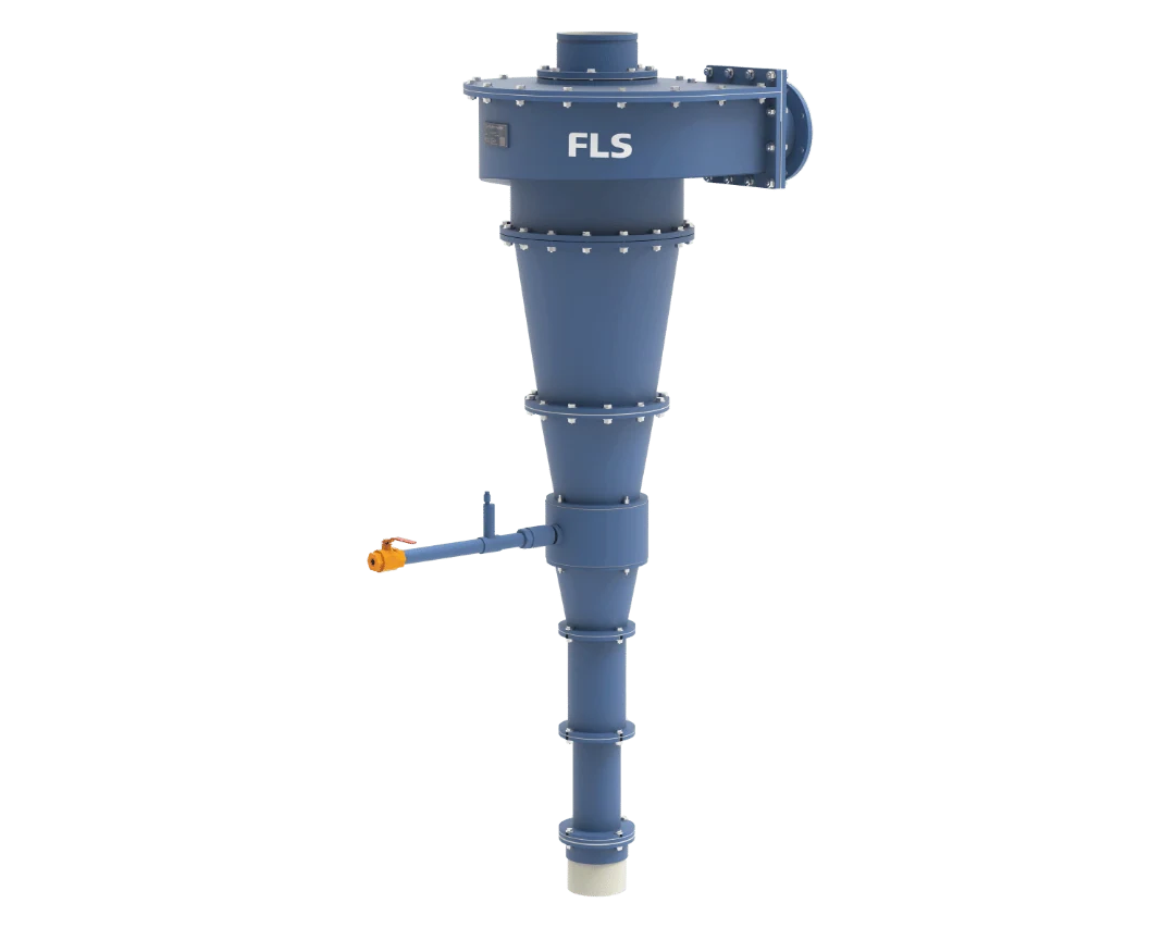
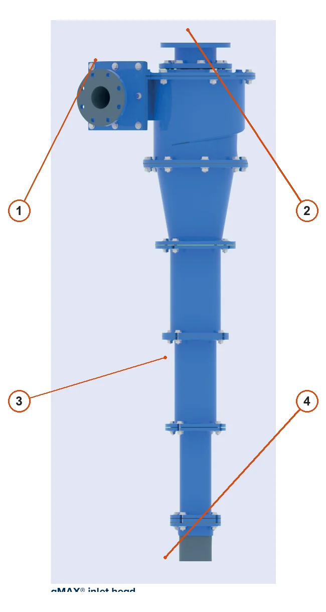
Official FLS KREBS إعصار gMAX المائي product image
Official FLS KREBS gMAX product image, showing the inlet head, cylinder, segmented cone, overflow and underflow outlets.
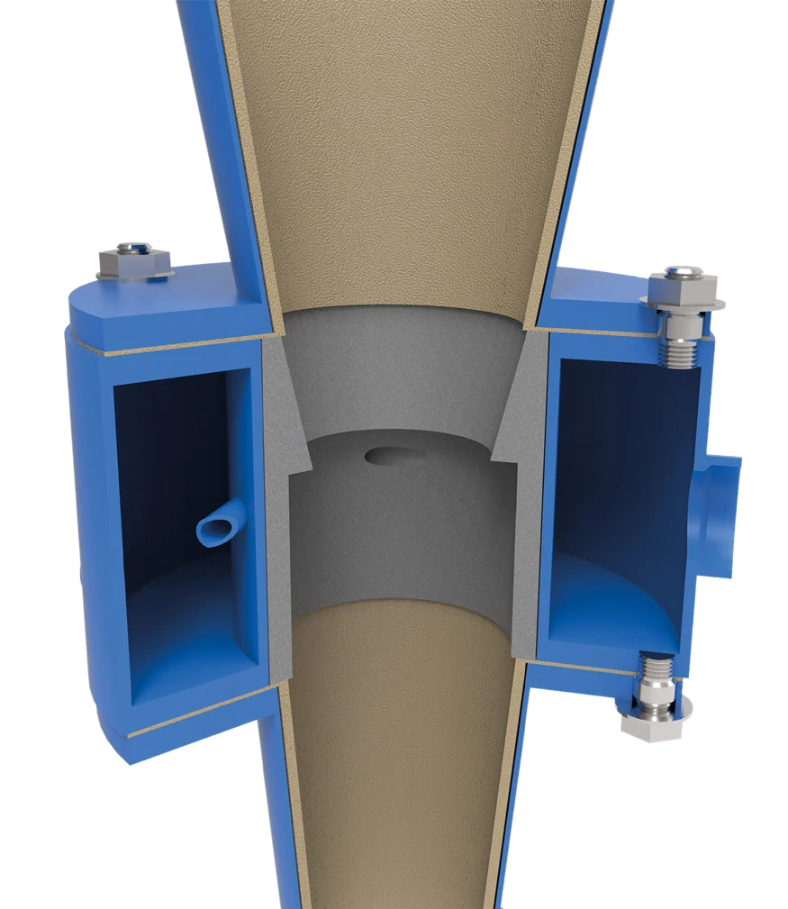
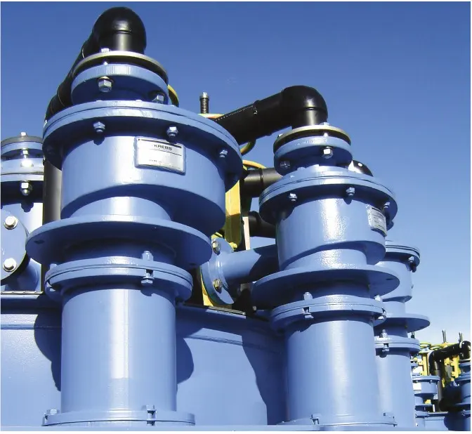
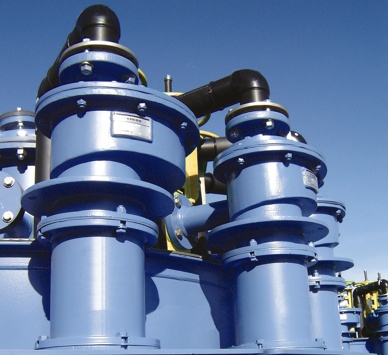
Official FLS KREBS إعصار gMAX المائي installation photo
gMAX installation photo from the official FLS brochure, showing units, upper piping and cyclone cluster connections.
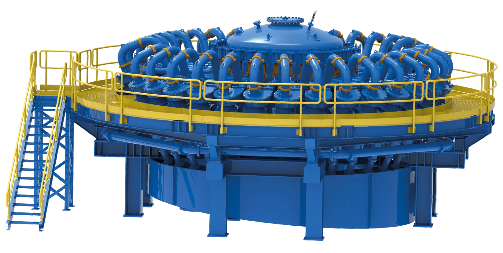
Official FLS KREBS gMAX multi-unit cyclone cluster photo
Multi-unit cyclone cluster in the official FLS brochure, showing manifolds, isolation valves, supports and site layout.
OEM المعدات التفاصيل

Models, wear liners, structural spares and materials on one page

gMAX classifies material through the combined geometry of the inlet head, cylinder, compound cone sections and underflow outlet. Before quotation, match the full model, diameter, cone arrangement, vortex finder, spigot, liner material, serial number and drawings to the same unit.

9 Verified series/model entries
8 Wear parts
4 Structural spares
4 OEM documentation
Models and key dimensions

gMAX series and standard molded polyurethane models

Diameters and capacities come from the official FLS KREBS brochure. Published capacities at 10–30 psi support model identification only. Actual selection and spares require the individual installation records.

Series / modelStandard diameter / structurePublished capacityApplication and document statusRequired spare identification
gMAX HydrocyclonesMetal housing / replaceable liner seriesProject-specific combination of diameter, inlet, cylinder, cone angle, vortex finder and spigotMineral processing, oil sands, power generation, chemicals, industrial manufacturing and water treatmentConfirm parts against the full model, serial number, structural configuration and drawing revision
U0.513 mm (0.5 in)0.2–0.3 m³/hMolded polyurethane cyclone capacity range at 10–30 psiCheck flow passages, interfaces, configuration and installation parts list
gMAX1U25 mm (1 in)0.7–1.1 m³/hMolded polyurethane gMAX modelافحص واجهات المدخل والتفريغ العلوي والتفريغ السفلي والمشعب
U2-gMAX51 mm (2 in)1.7–5.5 m³/hMolded polyurethane gMAX modelافحص واجهات المدخل والتفريغ العلوي والتفريغ السفلي والمشعب
U3-gMAX76 mm (3 in)3.2–12.5 m³/hMolded polyurethane gMAX modelافحص واجهات المدخل والتفريغ العلوي والتفريغ السفلي والمشعب
gMAX4U102 mm (4 in)5.4–17.3 m³/hMolded polyurethane gMAX modelافحص واجهات المدخل والتفريغ العلوي والتفريغ السفلي والمشعب
gMAX6U152 mm (6 in)13–33 m³/hMolded polyurethane gMAX modelافحص واجهات المدخل والتفريغ العلوي والتفريغ السفلي والمشعب
gMAX10U254 mm (10 in)22–114 m³/hMolded polyurethane gMAX modelافحص واجهات المدخل والتفريغ العلوي والتفريغ السفلي والمشعب
gMAX15U381 mm (15 in)114–273 m³/hMolded polyurethane gMAX modelافحص واجهات المدخل والتفريغ العلوي والتفريغ السفلي والمشعب
قطع الغيار المستهلكة

Inlet heads, cylinders, compound cones, vortex finders and spigots

Follow the slurry through entry, pre-classification, cylindrical swirling flow, cone classification, overflow and underflow. Each item links to the relevant part and material pages.

Inlet head and feed chamber liner positions in the FLS KREBS gMAX
01

Inlet Head / Feed Chamber Liners

Inlet Head / Feed Chamber Liner

These liners face high-velocity slurry erosion and particle impact in the tangential inlet and pre-classification zone. Check the full gMAX model, inlet direction and size, internal profile, liner segments, thickness, hole pattern, seals and adjacent cylinder interfaces.

Material and manufacturing checks:FLS lists BPC rubber, neoprene, nitrile rubber, chlorobutyl rubber, alumina and several silicon carbide ceramics as liner options. Screen these against particle size, concentration, pressure, corrosion and maintenance interval.

View Part التفاصيل →
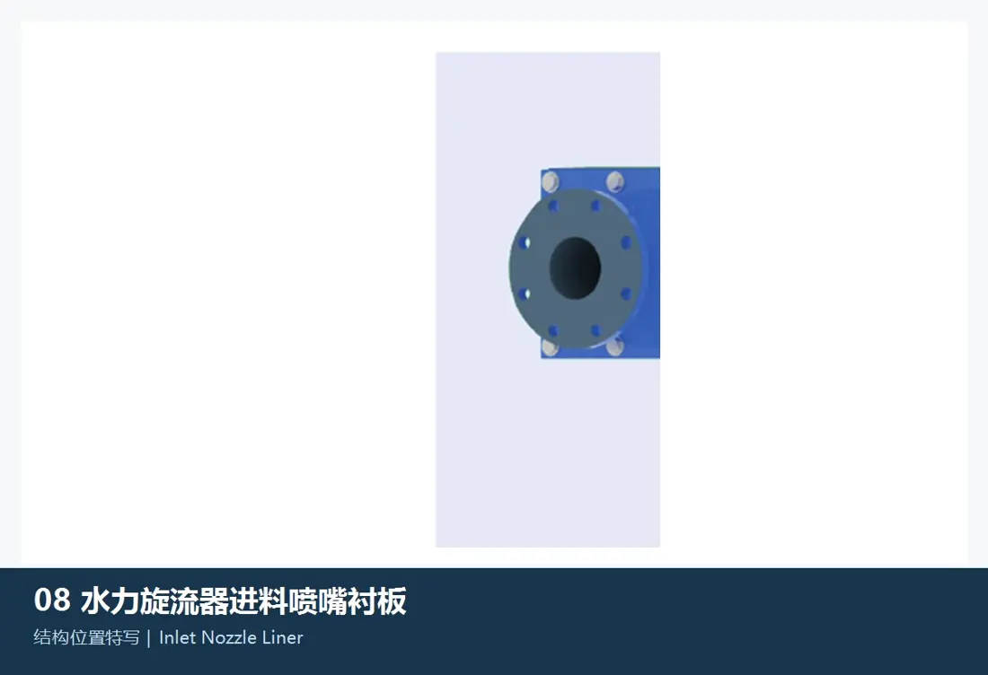
Inlet nozzle liner position in the FLS KREBS gMAX
02

Inlet Nozzle Liners

Inlet Nozzle Liner

These protect the feed interface and areas with the greatest flow-direction changes. Check inlet cross-section, flange, flow direction, profile, liner projection, end seals, fastening method and inlet head fit.

Material and manufacturing checks:Rubber, polyurethane and wear ceramics are material families for initial selection only. Confirm final material and structure against the original liner, operating conditions and drawings.

View Part التفاصيل →
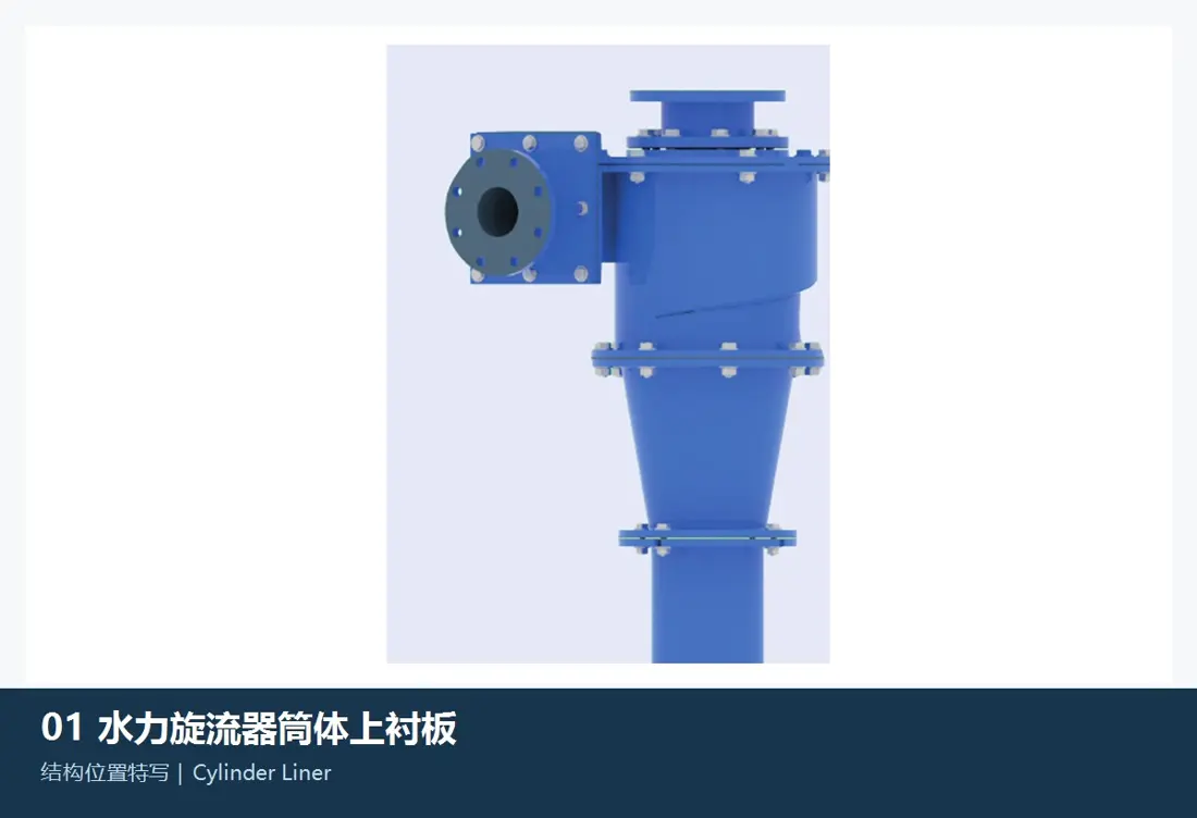
Cylinder and upper liner positions in the FLS KREBS gMAX
03

Cylinder Liners / Upper Liners

Cylinder Liner / Upper Liner

These protect the cylinder below the inlet head and maintain its critical inside diameter. Check cylinder diameter, section count, liner inside/outside diameters, length, flanges, hole patterns, joints, locating shoulders, swirl direction and inlet head position.

Material and manufacturing checks:Confirm BPC rubber, neoprene, nitrile rubber, chlorobutyl rubber, alumina or silicon carbide ceramics according to abrasion, corrosion, dimensional stability and replacement method.

View Part التفاصيل →
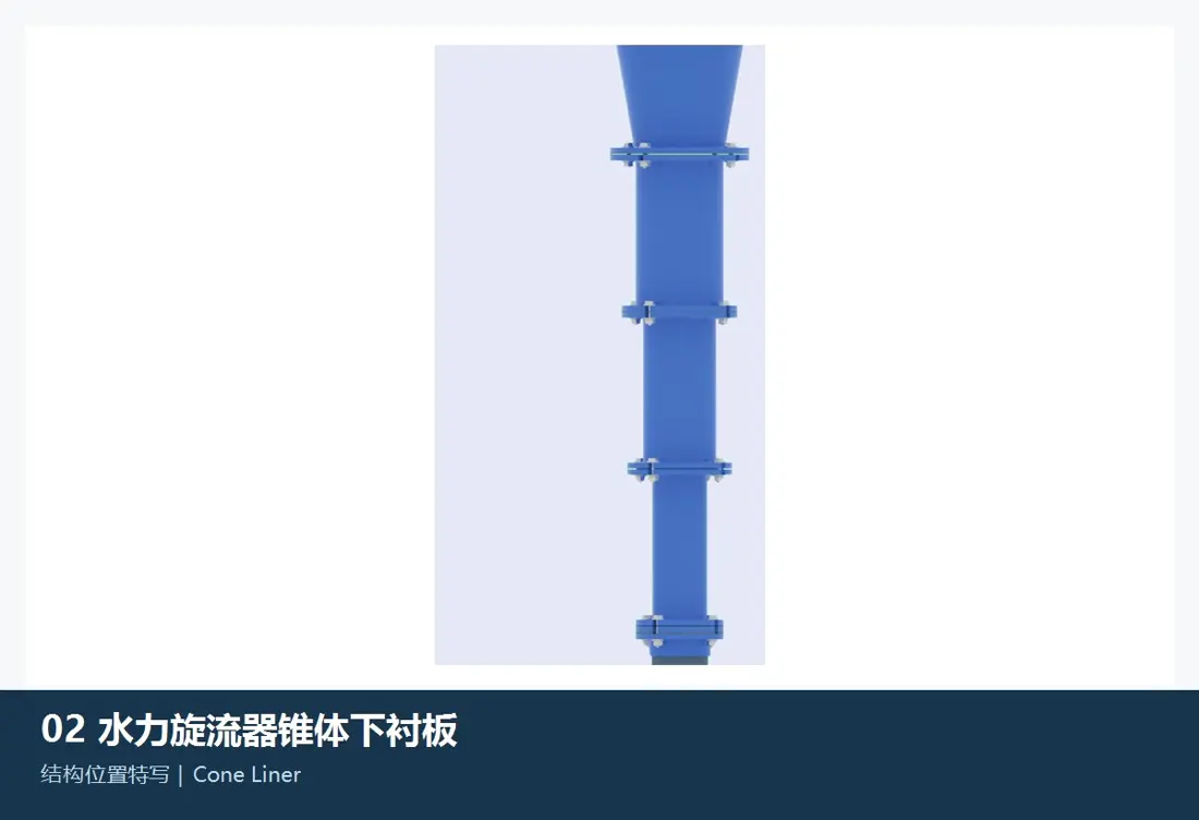
Upper and lower cone liner positions in the FLS KREBS gMAX
04

Upper and Lower Cone Liners

Upper and Lower Cone Liners

The gMAX compound cone liners determine the classification flow field and face increasingly concentrated abrasion. Check each cone's angle, length, large/small end diameters, flange, sequence, liner thickness, joints and transition to the underflow outlet.

Material and manufacturing checks:OEM documents state that advanced ceramics may be used in lower sections to extend wear life. Confirm alumina or nitride-bonded, reaction-bonded or sintered α silicon carbide options against the installation and operating conditions.

View Part التفاصيل →
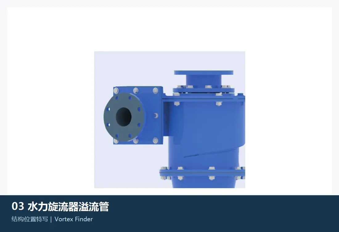
Vortex finder position in the FLS KREBS gMAX
05

موجه الدوامة

موجه الدوامة

The vortex finder fits at the top centre and controls the overflow passage. Check insertion depth, inside/outside diameters, overall length, top flange, fastening method, top cover liner fit and permitted wear.

Material and manufacturing checks:Confirm polyurethane, rubber or ceramic material families according to velocity, fine-particle erosion, stiffness, corrosion and removal method.

View Part التفاصيل →
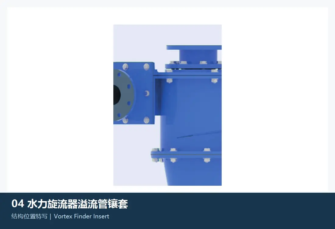
Vortex finder insert position in the FLS KREBS gMAX
06

موجه الدوامة Inserts

موجه الدوامة Insert

These are replaceable wear components in the overflow passage. Check inside diameter, wall thickness, insertion length, steps, locating shoulders, top retention, fit with the vortex finder body and passage roundness.

Material and manufacturing checks:Confirm ceramic or polyurethane designs against original structure, pressure differential, abrasion and maintenance strategy. المعدات diameter alone does not establish interchangeability.

View Part التفاصيل →
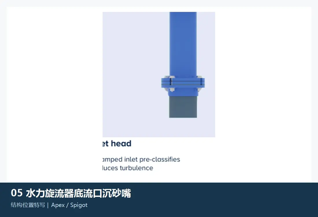
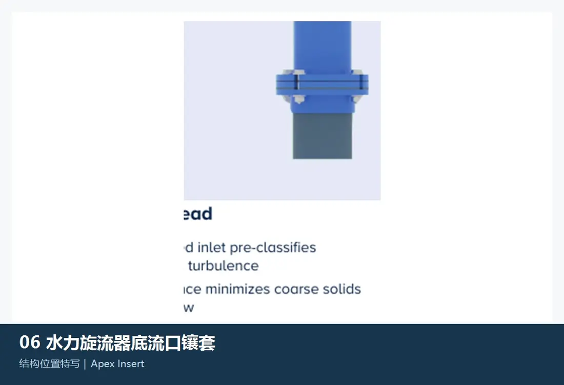
Underflow spigot and apex position in the FLS KREBS gMAX
07

مخرج النفايات السفلية / القمة

Apex / Spigot

The spigot sits at the lowest point and determines the underflow outlet. Check full model, bore, shape, taper, overall length, flange or clamping method, insert structure, permitted wear and final cone interface.

Material and manufacturing checks:FLS-listed rubber, polyurethane, alumina and silicon carbide options require confirmation against outlet bore stability, erosion and blockage risk.

View Part التفاصيل →
قطع الغيار

Inlet head housings, cylinder sections, cone housings and cyclone clusters

Hydrocyclones have no mechanical drive parts. This section covers structural spares directly related to pressure boundaries, liner support, manifolds, valves, seals and site installation.

Inlet head housing position in the FLS KREBS gMAX
01

Inlet Head Housings

Inlet Head Body

These support the inlet, top cover, vortex finder and cylinder interfaces. Check housing material, inlet direction, flange standard, hole pattern, pressure rating, top cover, liner cavity dimensions and lifting positions.

Material and manufacturing checks:FLS lists unlined housing materials including 304L/316L stainless steel, Duplex 2205, CD4MCU, Monel, Inconel, Nickel, Hastelloy and other metal alloys. Confirm the grade against the fluid and original drawings.

View Part التفاصيل →
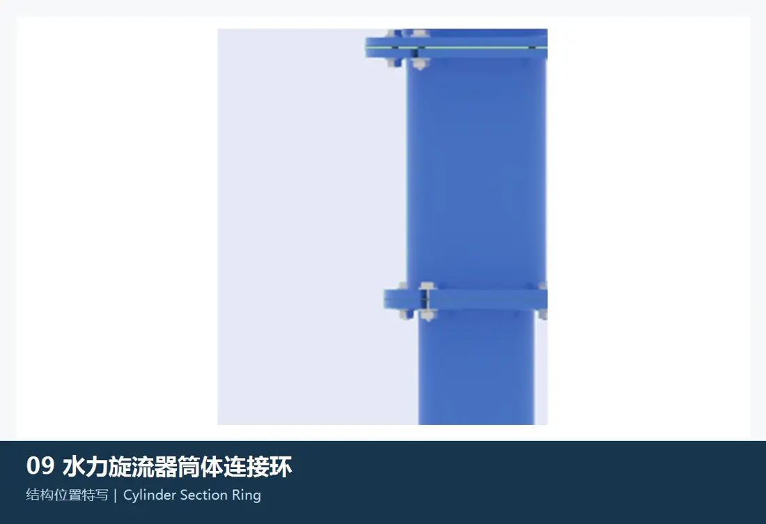
Cylinder section and connecting ring positions in the FLS KREBS gMAX
02

Cylinder Sections and Connecting Rings

Cylinder Section and Ring

These form the pressure boundary and liner support between the inlet head and cones. Check diameter, section length, flanges, hole spacing, seal grooves, housing thickness, connecting rings, liner cavity and adjacent section orientation.

Material and manufacturing checks:Confirm metal housings, one-piece polyurethane components and seals against pressure, corrosion, temperature and original structure.

View Part التفاصيل →
Cone housing assembly position in the FLS KREBS gMAX
03

Cone Housing Assemblies

Cone Section Body Assembly

Multi-section cone housings must retain the correct sequence, cone angles and flow continuity. Check each section's large/small end diameters, length, flanges, hole patterns, housing material, liner space, seals and supports.

Material and manufacturing checks:Confirm housing and liner materials separately. Metal housings must meet pressure and corrosion requirements; liners must meet abrasion and flow-passage dimensional requirements.

View Part التفاصيل →
Cyclone cluster manifold, valve and support positions in the FLS KREBS gMAX
04

Cyclone Cluster Manifolds, Valves and Supports

Cluster Manifold, Valves and Support

Multiple cyclones form a cluster through feed manifolds, isolation valves, overflow/underflow collection, supports and instruments. Check unit count, pipe diameters, valves, pressure ratings, interfaces, centre distances, supports and site layout.

Material and manufacturing checks:Confirm piping, valves, liners, seals and structural steel separately against pressure, abrasion, corrosion and installation documents.

View Part التفاصيل →
OEM material range

Confirm liner materials separately from unlined housing materials

The FLS gMAX brochure lists BPC rubber, neoprene, nitrile rubber, chlorobutyl rubber, alumina, nitride-bonded silicon carbide, reaction-bonded silicon carbide and sintered α silicon carbide liners. Unlined housings include 304L/316L, Duplex 2205, CD4MCU, Monel, Inconel, Nickel, Hastelloy, other metal alloys and polyurethane. A material name alone is not a manufacturing specification: installation position, pressure, abrasion, corrosion and original structure must also be confirmed.

Drawing and spare part numbers

Match OEM or third-party numbers to models, sections, bores and materials

When submitting a number, include the full gMAX model, serial number, cyclone diameter, inlet direction, cylinder/cone arrangement, vortex finder, spigot bore, liner material, drawings and used-part photos.

Is gMAX diameter alone enough to identify liners and spigots?

No. Also check the full model, inlet head, cylinder, cone arrangement, vortex finder, spigot bore, housing and liner materials, serial number and drawing revision.

How are gMAX liner materials selected?

Screen rubber, polyurethane, alumina, silicon carbide ceramics and corrosion-resistant alloys by installation position and failure mode, then confirm against original structure, operating conditions, dimensions, drawings and acceptance requirements.

Submit FLS KREBS gMAX models, drawing numbers, liners or structural spare requirements

Provide the full model, serial number, inlet direction, cyclone diameter, cone arrangement, vortex finder, spigot bore, OEM/third-party number, drawings, used-part photos, material and operating conditions. We use these to identify parts, assess materials, match manufacturing requirements, control quality and deliver finished components.

طلب مراجعة المشروع

رقم الهاتف: +86 156 3797 3199
zzx@anranst.com

خدمات صنع في الصين

من التقييم الفني إلى تسليم المنتج بالكامل

توفر شركة ANRANST للعملاء العالميين تقييمات هندسية، واختيار التصنيع الصيني، ومراقبة الجودة، وتسليم الأجزاء النهائية لقطع الغيار الصناعية المقاومة للتآكل حسب الطلب، ويمكنها أيضًا دعم قطع الغيار الصناعية الأخرى حسب الطلب.

01

مراجعة الرسومات والهندسة

قم بمراجعة أسطح التزاوج وأبعاد الواجهة، وقم بتقييم جدوى المواد والمعالجة الحرارية والتصنيع.

02

تحديد المادة والمعالجة الحرارية

تُحدَّد درجات المواد وعمليات المعالجة الحرارية لكل طلب على حدة، وتُثبَّت في الاتفاقية الفنية وتُتابَع أثناء الإنتاج.

03

ضبط الجودة

يشمل ذلك تأكيد الرسم، ومراقبة المواد والعمليات، وتتبع الإنتاج، وتنسيق عمليات الفحص والقبول.

04

تسليم المنتج النهائي

تنظيم عمليات التصنيع والتحقق من الجودة والتعبئة والتغليف وتسليم المنتجات النهائية الكاملة لتشكيل حلقة إمداد قابلة للتنفيذ.

قم بتزويدنا بالنماذج الحالية، والرسومات، وأرقام الرسومات، وأرقام الأجزاء، والمواد، أو معلومات ظروف التشغيل، وسنقوم بتحديد التحقق الفني ومسار التوريد وفقًا لذلك.

إرسال طلب