FLS WEMCO II, nextSTEP, mixedROW and RFC Flotation Equipment

First, distinguish self-suction and forced inflating processes from the combination process to column float selection (REFLUX) as well with crude particle floating structures. Then enter corresponding wet endwear parts for transmission spare parts of materials drawing number confirmation or RFQ

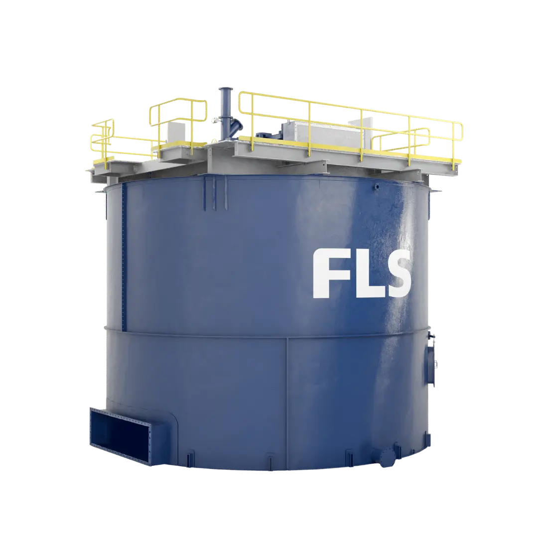
FLS WEMCO II Self-suction floating slot official map
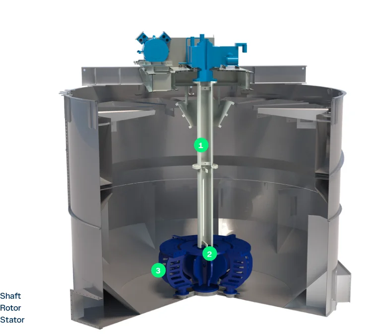
FLS WEMCO II Self-suction floating slot official full map; the rotor is located on top of a sink, wet Construction and nextSTEP Different.
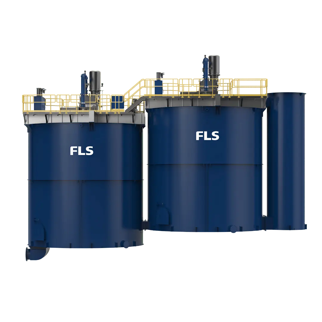
FLS nextSTEP Mandatory inflatable floating slot official full-frame
FLS nextSTEP The official diagram of the forced inflatable floating slot; a rotor/fix is located at bottom and supplied by an external blower system.
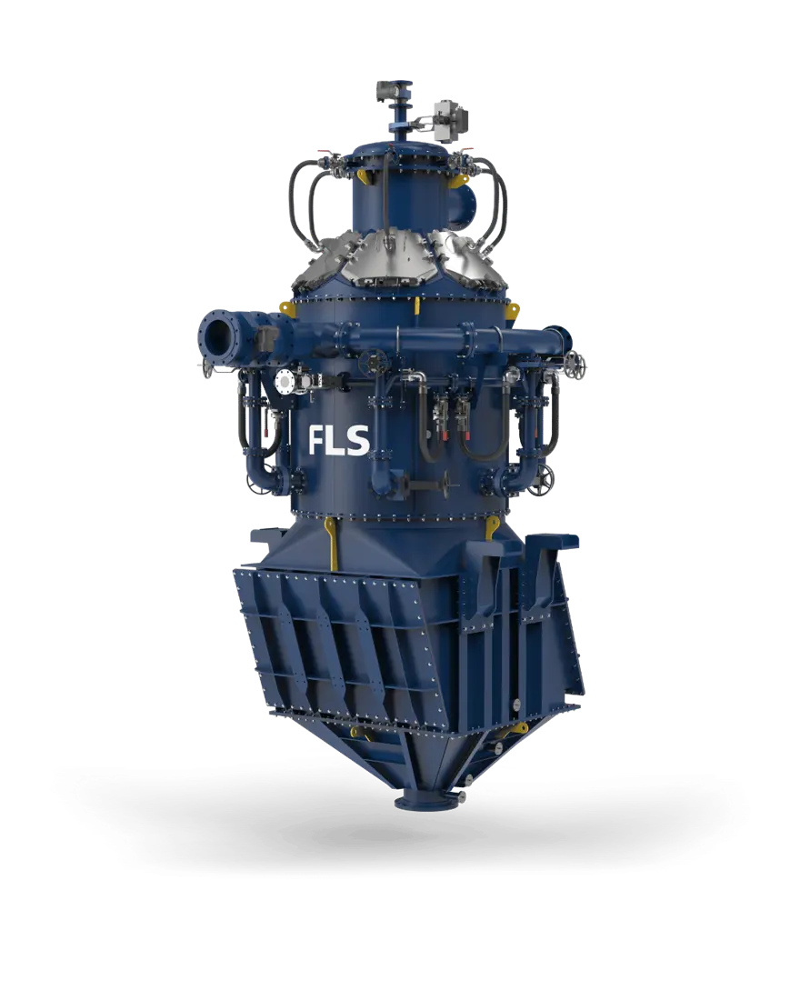
FLS REFLUX RFC2000 Flotation Equipment Official full-length diagram
FLS REFLUX RFC2000 Official full-frame diagrams; its inflating, tilted channel and pressure Construction Cannot be fitted with mechanical floating slots spare parts.
OEM Equipment Details

Equipment Series APPLICABLE parts and materials Completed on a page

FLS Floating product lines contain a variety of completely different structures. This page retains only the current series, open size range and core wet end parts for Spare Part Identification requirements; transmission portion selection (S) material screening / drawing number check-up as well ASRFQ entry to clarify each part' scope application

7 Current Series / Specifications line
7 Wet stalk wear parts Entrance
4 Core spare parts Entrance
8 Original Factory Information Entry
Current Series and Key dimensions

First Judge Construction, and again judging parts

Open size is only used Identification Product scope; actual spare parts We have to go back into completeness. Series, and the volume of condensation. serial number, drawing number, P & ID, general arrangement drawing and current Drawing Revision.

Series / ModelConstructionOpen Scopespare parts Key identification details
WEMCO IISelf-suction mechanical floatWEMCO II Square grooves, WEMCO II RT Rounds, WEMCO II Inert GasTransformers, dispersors and decentralizers masking the false bottom of a duct/stewing tube Power Transmission Total: Three Construction Converged by the installed archives
nextSTEPForced inflatable mechanical float selectionrectangle slot effective volume – m; Round slots effective volume – m ³ (1.7; 2.8; 5; 600)nextSTEP Transformers/Candles, Cedes Bottom Plate, the rotor-drive shafts BHSA, belt wheels and foams & liquid level control parts
mixedROWnextSTEP and WEMCO Combination ProcessAdaptable – m Loading (5; 660)The same row is in two mechanical Construction.Differences must be made by specific slot WEMCO and nextSTEP Wet end-piece
FLS ColumnCategory: Pillar float selectionCross-sectional area – m. Operating volume – m ³ (0.79; 28.27; 2.5; 472.5)External Wenchurian inflatable system, circulating pumping machine and sprayer; no mechanical rotor/fix
RFC300 / RFC500REFLUX Flotation CellDiameter 300 / 500 mm; Total inlet pulp 5 – 13 / 14 – 35 m ³/ hPre- Contact inflatables, tilting channels and effluent water. Pressure chamber Valve parts; not used WEMCO/nextSTEP parts
RFC SeriesREFLUX Flotation CellOpen selectors are listed RFC300, 500, 850, 1400, 1750, 2000, 2350, 2750, 3000, 3600Specific Item Dimensions, traffic and spare parts s complete model, serial number, P & ID and Drawing Revision Confirmation
coarseAIRFlow of coarse particlescA-100 (test-level) cA-850 (industrial level), open diameter 100 / 850 mmNo traditional internal mechanical rotors; spare parts Focus on inflating, ductping and Valve parts, slots and modules Interfaces

RFC300 / RFC500 The traffic is FLS The current page is publicly available; other RFC model and all Item Configuration Manufacturing The previous data are matched by the current original factory information and installation drawings.

Wear Parts

s WEMCO, nextSTEP Differences between wet end parts and slot location

Transformers, dispersors/fixes and hooded bodies can not be interchanged only by Chinese name; each card first indicates the applicable structure to connect unified parts pages with materials.

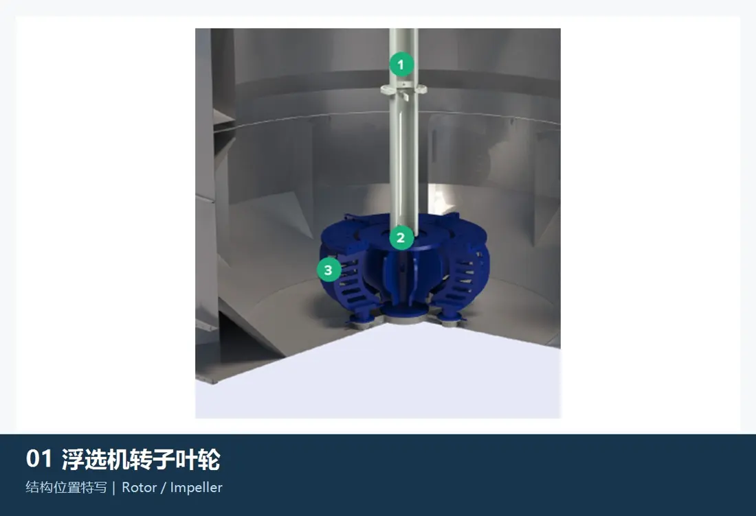
Rotor / Impeller FLS Flotation Equipment the s Construction and installation position References
01

Rotor / Impeller

Rotor / Impeller

Applicable Configuration: WEMCO II / nextSTEP / mixedROW Relatively trough

WEMCO II self-suction rotor and nextSTEP forced inflator rotary are core wet end parts, but the height of installation is different from air path to outline or supporting parts. Contrast series trough volume: rotational diameter; bore lineage (Axle connection) with actual wear profile

Materials and Manufacturing: Elastomer coating, polyurethane or original design composite structures are confirmed by mineral abrasion requirements pharmacist temperature and rotation speed as well AS equilibrium; not the generic material name replaces OEM drawings.

View Part Details →
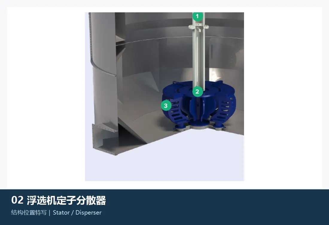
Stator / Disperser FLS Flotation Equipment the s Construction and installation position References
02

Stator / Disperser

Stator / Disperser

Applicable Configuration: WEMCO II Decentralizer / nextSTEP Fixed

NextSTEP uses the supporting tuner, WEMCO II using a decentralizer; both function and structure are different from their installation positions. Contrast series (slot volume), blade/window profilees of bottom-up pores systems) with gaping interval or rotational numbers as well in paired number to rotor units

Materials and Manufacturing: elastomers, polyurethane Or original design complex Construction Acknowledged by abrasion, tearing and compatibility of the drug with matchmaking gaps.

View Part Details →
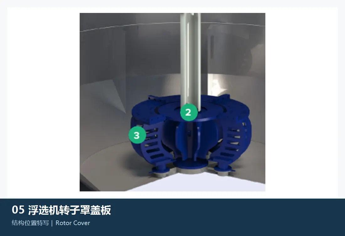
Dispersor / Transformers in FLS Flotation Equipment the s Construction and installation position References
03

Dispersor / Transformers

Disperser Hood / Rotor Cover

Applicable Configuration: WEMCO II / WEMCO 1 + 1 Installer Construction

The main receptor is WEMCO self-sorbing structure for forming air and mineral flow paths, as well to protect the wet side. Converging between Vemco'S intergenerational patterns of volumetric fluidity (WMECo), capsules profiles; windows/flange structures: bearing lines or gap with dispersors\ rotor).

Materials and Manufacturing: rubber or polyurethane Package Construction Acknowledged by abrasion, fatigue and pharmacological consistency as well in molding sizes.

View Part Details →
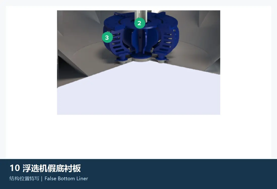
False Bottom Liner / False Foundation Part / Assembly FLS Flotation Equipment the s Construction and installation position References
04

False Bottom Liner / False Foundation Part / Assembly

False Bottom Liner / False Floor

Applicable Configuration: WEMCO II / WEMCO 1 + 1 Installer Construction

The main corresponding to the WEMCO self-suction groove is used for organizing bottom mineral flow and protecting sink. Contrast tank form, blockage plate thicknesses of holes in a rowing system with an interface boundary between current flows as well AS/SWIFT gap

Materials and Manufacturing: rubber, polyurethane, corrosion-resistant steel or composite substrates by mineral pulp abrasion and resination agents. Construction stiffness confirmation.

View Part Details →
Tubes/Plastic Pipeline FLS Flotation Equipment the s Construction and installation position References
05

Tubes/Plastic Pipeline

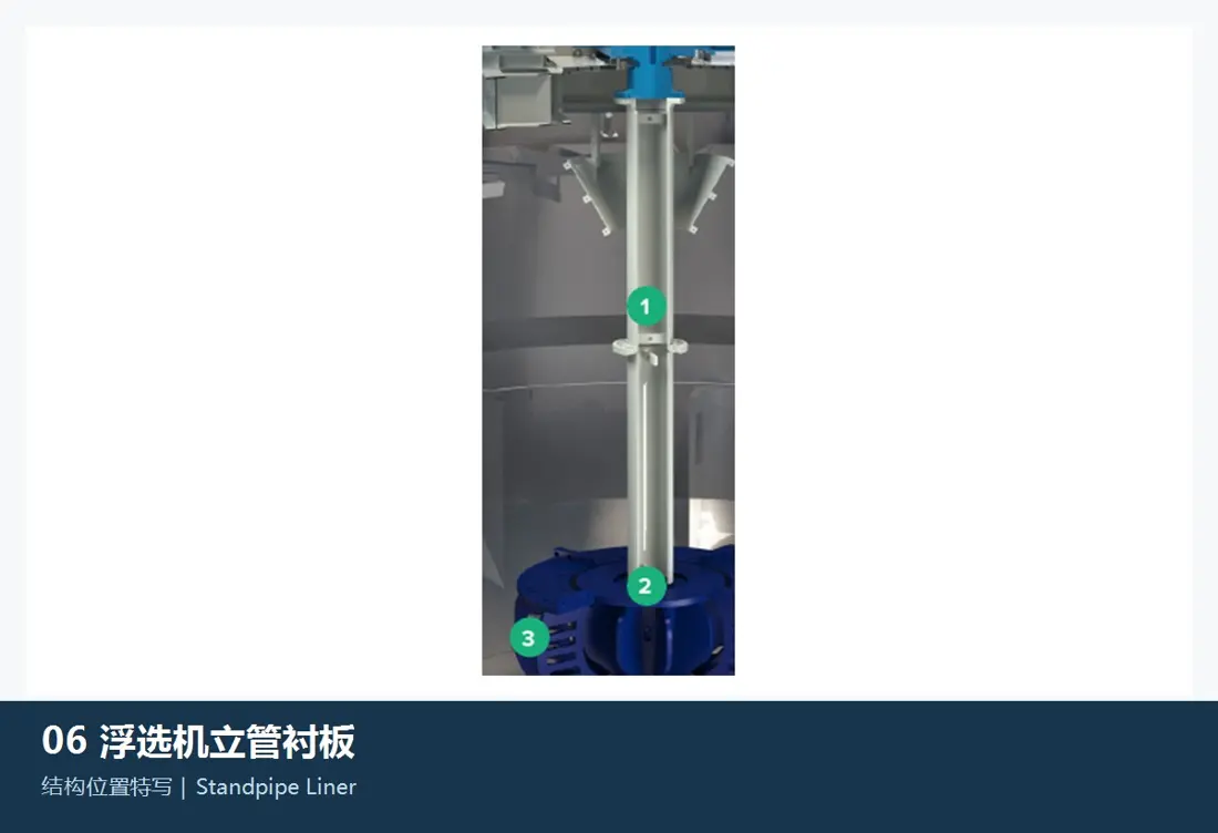
Draft Tube / Standpipe Liner

Applicable Configuration: WEMCO II / WEMCO 1 + 1 Installer Construction

The main fitting is the WEMCO self-suction structure, which connect a false bottom area to an upper rotor loop path. Contrast control diameter and length of flange with bearing; inner wall thicknesses: concentricity - interface between transponder gap & slot machine

Materials and Manufacturing: rubber, polyurethane Or corrosion-resistant alloy Construction Recognize by scrubbing, pharmaceutical agents and bonding methods as well.

View Part Details →
Trough Liner FLS Flotation Equipment the s Construction and installation position References
06

Trough Liner

Cell / Tank Liner

Applicable Configuration: s WEMCO / nextSTEP / Column / RFC The drawings are confirmed separately

Protection of mechanical floating slots, columns or local high wear areas. Contrast equipment series and shape groove area; installation zone: partitioning the plate thicknesses (plate) with a hole lineage - seam connector to repair doors as well in-house parts gap

Materials and Manufacturing: rubber, polyurethane resistant steel or composite substrates by mineral pulp abrasion, corrosion and purification operating conditions Confirmation.

View Part Details →
The sludge valve wet finishes are FLS Flotation Equipment the s Construction and installation position References
07

Offload valve wet-end thread

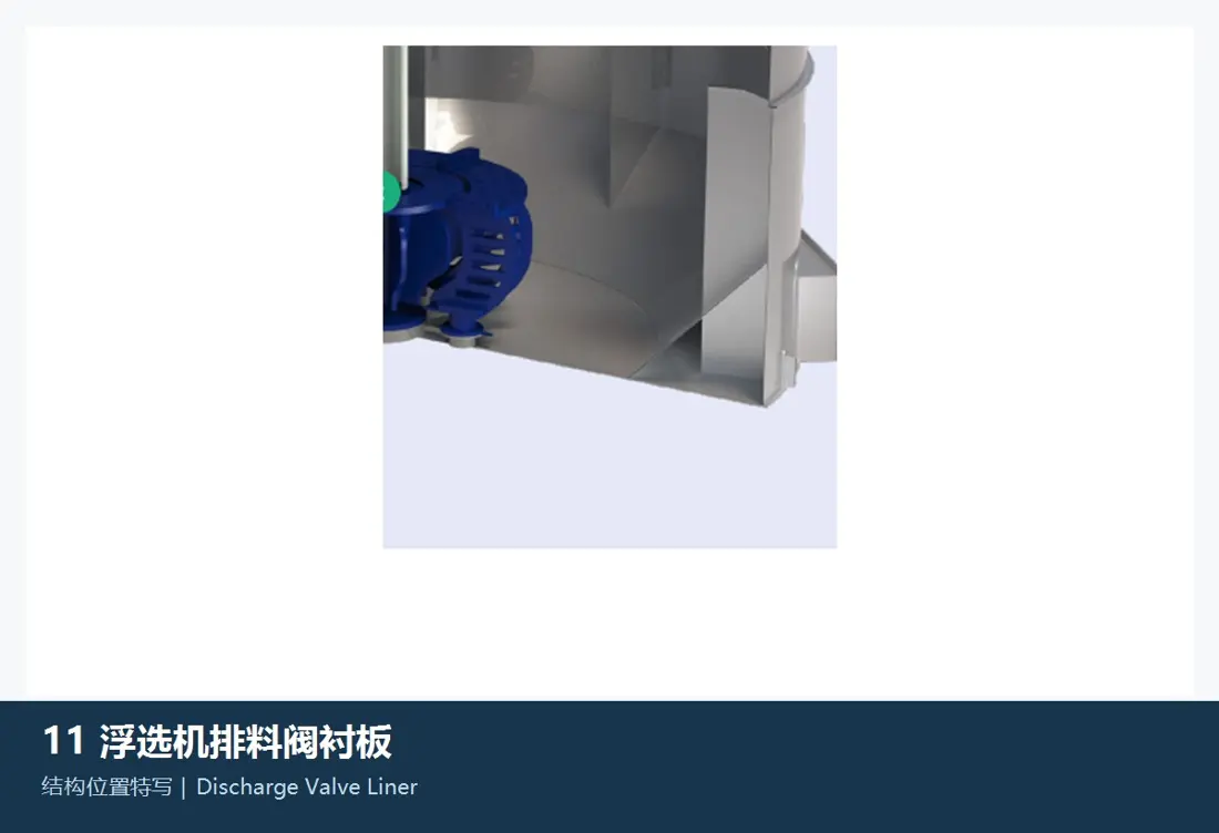
Discharge / Dart Valve Wet-end Liner

Applicable Configuration: Mechanical Floating Load / mixedROW Specific Valve Types by Drawing

Protection of inter-groove discharge, fluid level adjustment or bottom flow Valve parts the slurry of mines Contact Face: Contrast valve shape, slots and duct diameter. Guiding, the actuator Interfaces and the tide.

Materials and Manufacturing: rubber, polyurethane, ceramic Or corrosion-resistant alloys are confirmed according to pressure differential, abrasion and pharmacists & sealing requirements.

View Part Details →
Spare Parts

Driver shafts, wheels and BHSA With the squirrel organ

Power Transmission and the bearer of both Interfaces Accuracy, swirlness and Speed Airways, Bearings and Seals, and the corresponding machinery Construction Confirms the volumetric hull together.

Transponder-Driven Oscillation Shaft Sleeve FLS Flotation Equipment the s Construction and installation position References
01

Transponder-Driven Oscillation Shaft Sleeve

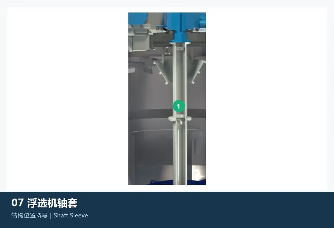
Rotor Drive Shaft and Sleeve

Applicable Configuration: WEMCO II / nextSTEP / mixedROW Relatively trough

Transfer torque from the drivetrain to wet ends. Converging WEMCO or nextSTEP Construction, total lengths and axes diameter; empty air passageways: key/foaming button. bearing Locations, sealing positions and vortex balance.

Materials and Manufacturing: Forged Alloy Steels for Drive Parts, Stainless Steel Or the original design surface Protection, heat treatment axis and neck precision NDT Confirm by the drawings and transmuted loads.

View Part Details →
Rotor Hub / The Connector in FLS Flotation Equipment the s Construction and installation position References
02

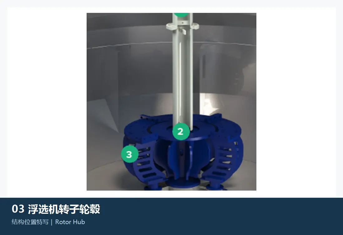
Rotor Hub / Connector

Rotor Hub / Mounting Hub

Applicable Configuration: Mechanically mechanic Flotation Machine Template: Construction

Connecting the drive shaft with rotor or wet sutures Part / Assembly Converging the aperture, key/wafers and cone to flanges or bolt holes; positioning surfaces. Turnover of space with alignment

Materials and Manufacturing: Alloy Steels for Drive Parts Or resistant to corrosion, heat treatment, size accuracy and corrosion protection by torques of the mineral pulp environment as well.

View Part Details →
bearing Boxes, Bearings and Seals FLS Flotation Equipment the s Construction and installation position References
03

bearing Boxes, Bearings and Seals

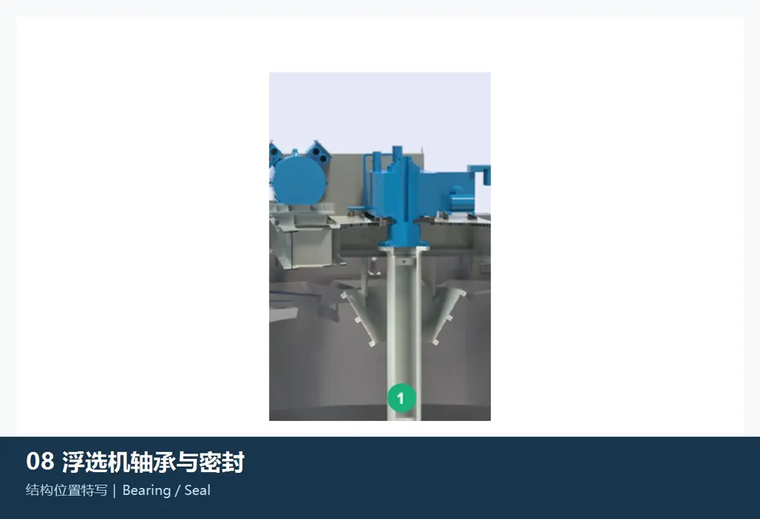
BHSA / Bearing and Seal

Applicable Configuration: WEMCO II / nextSTEP / mixedROW Relatively trough

FLS open spare parts range from bearing boxes to axis parts BHSA. Contrast the type of organ, carrying codecs and gaping areas; axle/seat fit for sealant structures: Lubrication & speed transmission with high load levels as well in installation standards

Materials and Manufacturing: bearing Steel, Alloy Steels for Drive Parts and oil resistant/chemical Seal Materials Recognized by load, temperature and mineral slurry.

View Part Details →
Sparking boards / Foam leaving the body in FLS Flotation Equipment the s Construction and installation position References
04

Sparking boards / Foam-freezing bodies

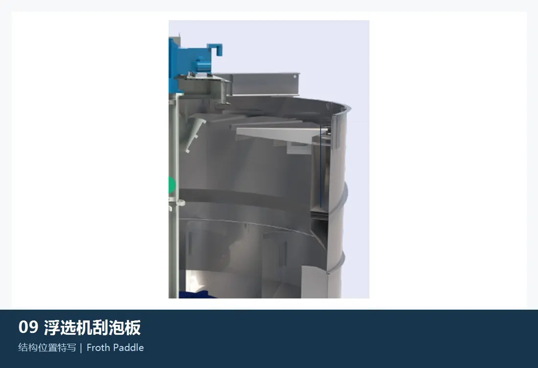
Froth Paddle / Skimmer

Applicable Configuration: WEMCO II Optional Construction Other sloping bodies

Mechanical auxiliary recovery for thin or slow flow foams. Contrast the slot, lobe length and diameter of a hole in size with rotational direction; shaft (chain/gear transmission), speeding - bearing & bubble interface

Materials and Manufacturing: Stainless Steel, engineering plastics or rubber Package Construction By corrosion, foams and weighting operating conditions Confirmation.

View Part Details →
Drawing and Spare Part Numbers

s OEM or third-party number corresponds to Series, slots and Construction

The full series, volume of the slots and serial number are provided at submission with groove numbers as well. Structure such is WEMCO/nextSTEP or RFC; part names: drawings - photos from used parts (key dimensions), materials for operation conditions in mineral pulp).

WEMCO II and nextSTEP Is the rotor, dispersor or dent universal?

Inconvenient. The two modes of ingress, the rotor-installation position and profile are different from those that support dispersors/fixes to substrates or gap; they must be confirmed by full series (groove volume), serial number as well for drawings).

Column, REFLUX RFC and coarseAIR Can I use a mechanical float slot parts ?

They do not. The spare parts must be identified according to their respective lanes, valve pieces and slot machines as well for the design drawings respectively using external inflators or tilt channels/pressure chamberes; they are also used by bulk pellet floating structures which require separation of spare parts on each other' own pathways (wallets), sinking plates - etc).

Submission FLS Flotation Equipment Series, and the volume of condensation. drawing number Or Core spare parts Demand

Provide complete series, volume of the slots. Serial number and position numbers; OEM/Third Party Number: drawings & photos from used parts (key sizes), materials with mineral working conditions for part identification purposes - material assessment to manufacture matching requirements as well quality control in finished-part delivery

Manufacturing Services in China

From Technical Assessment to Finished-Part Delivery

ANRANST provides customers worldwide with coordinated consulting, supplier sourcing, quality control and finished-part delivery for custom parts, wear parts and industrial spares from China, with scope to support other custom industrial parts.

01

Technical Advice

Equipment and part identification, drawing review, material selection and manufacturing feasibility assessment.

02

Supplier Introductions

Match requirements with suitable manufacturers in China and coordinate the exchange of technical information.

03

Quality Control

Drawing confirmation, material and process control, production tracking, inspection and acceptance coordination.

04

Finished-Part Delivery

Coordinate manufacturing, quality confirmation, packaging and delivery of complete finished parts.

Provide the existing model, drawings, drawing or part numbers, materials or operating conditions so we can identify the appropriate technical review and supply route.

Submit an Enquiry