FLS WEMCO II, nextSTEP, mixedROW and RFC Flotation المعدات

First distinguish self-aspirating, forced-air, combined-circuit, column, REFLUX and coarse-particle designs. Then identify the appropriate wet-end wear parts, drive spares, materials and drawing references for quotation.

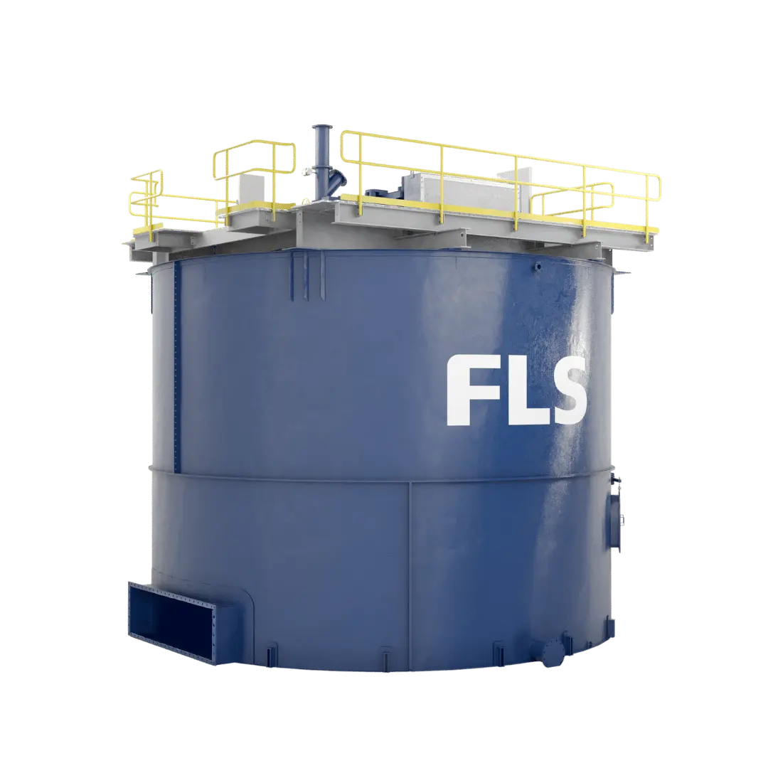
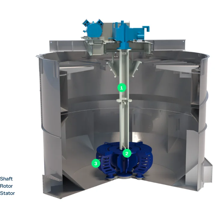
Official FLS WEMCO II self-aspirating flotation cell image
Official FLS WEMCO II self-aspirating cell image. The rotor is in the upper tank, and the wet-end design differs from nextSTEP.
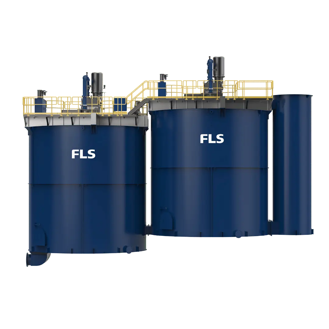
Official FLS nextSTEP forced-air flotation cell image
Official FLS nextSTEP forced-air cell image. The rotor/stator is at the tank bottom, with air supplied by an external blower system.
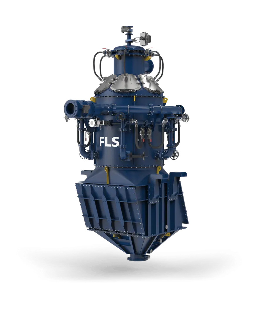
Official FLS REFLUX RFC2000 flotation equipment image
Official FLS REFLUX RFC2000 image. Its aeration, inclined channels and pressure design cannot use mechanical-cell spares by analogy.
OEM equipment guide

سلسلة المعدات, Applicable Parts and Materials on One Page

FLS flotation products include fundamentally different designs. This page covers current series, published size ranges, core wet-end and drive parts, material selection, drawing checks and quotation requirements, with the applicability of each part stated.

7 Current Series / Specification Entries
7 Wet-End قطع الغيار المستهلكة
4 Core Spare Categories
8 OEM References
Current Series and Key Dimensions

Identify the Design Before the Part

Published dimensions identify the product range only. Actual spares require the full series, cell volume, serial number, drawing reference, P&ID, general arrangement and current drawing revision.

Series / ModelDesignPublished RangeKey Spare-Part Identification Areas
WEMCO IISelf-aspirating mechanical flotationWEMCO II square cells, WEMCO II RT round cells, WEMCO II Inert GasRotors, dispersers, disperser hoods, false bottoms, draft tubes/standpipes and drive assemblies; verify all three designs separately against installation records.
nextSTEPForced-air mechanical flotationRectangular-cell effective volume 1.7–2.8 m³; round-cell effective volume 5–600 m³nextSTEP rotors/stators, stator base plates, rotor drive shafts, BHSA, pulleys, froth and level-control parts
mixedROWCombined nextSTEP and WEMCO circuitFor cells of 5–660 m³Two mechanical designs coexist in one row; distinguish WEMCO and nextSTEP wet ends by the specific cell position.
FLS ColumnColumn flotationCross-sectional area 0.79–28.27 m²; operating volume 2.5–472.5 m³External Venturi aeration, recirculation pumps, injectors, tanks and froth launders; no mechanical rotor/stator.
RFC300 / RFC500REFLUX Flotation CellDiameter 300 / 500 mm; total feed slurry 5–13 / 14–35 m³/hPre-contact aerators, inclined channels, fluidisation water, pressure chambers and valves; WEMCO/nextSTEP parts do not apply.
RFC SeriesREFLUX Flotation CellThe published selector lists RFC300, 500, 850, 1400, 1750, 2000, 2350, 2750, 3000 and 3600.Confirm project dimensions, flow rates and spares by full model, serial number, P&ID and drawing revision.
coarseAIRCoarse-particle flotationcA-100 (test scale); cA-850 (industrial scale), published diameters 100 / 850 mmNo conventional internal mechanical rotor; spares focus on aeration, piping, valves, tanks and module interfaces.

RFC300 / RFC500 flow rates are comparison values published on current FLS pages. Verify other RFC models and all project configurations against current OEM records and installation drawings before manufacture.

Wear parts

Distinguish Wet-End Parts by WEMCO, nextSTEP and Cell Position

Names alone do not establish interchangeability of rotors, dispersers/stators, hoods, false bottoms, draft tubes or valves. Each card states the applicable design before linking to component and material pages.

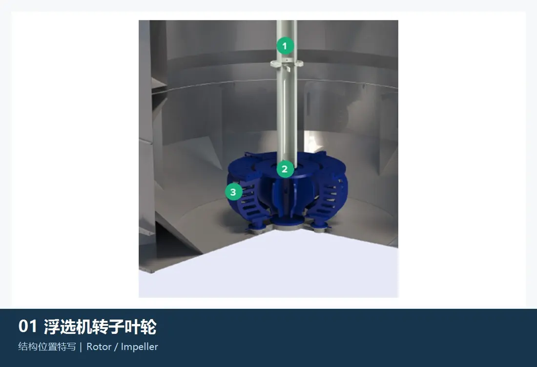
Rotor / Impeller — design and position in FLS flotation equipment
01

Rotor / Impeller

Rotor / Impeller

التصميم المطبق: مواضع خلايا WEMCO II / nextSTEP / mixedROW المقابلة

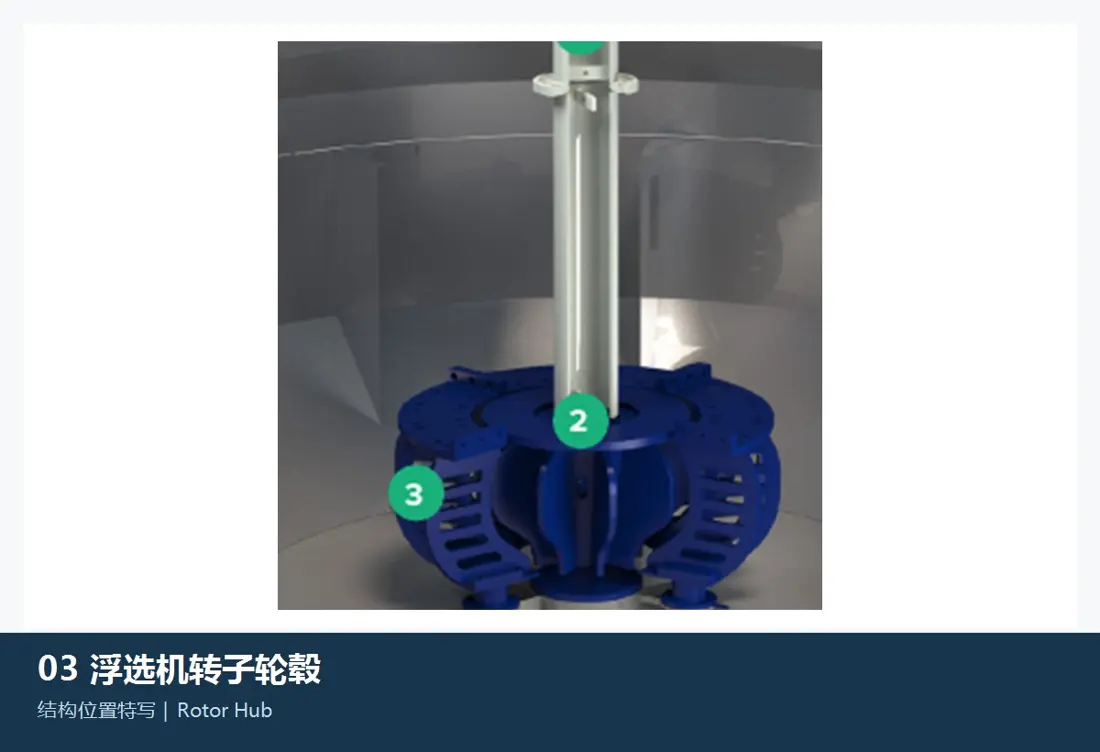
WEMCO II self-aspirating and nextSTEP forced-air rotors are core wet-end parts but differ in height, air path, profile and mating parts; they are not interchangeable. Check series, volume, rotation, diameter, holes, shaft connection and actual wear profile.

Material and manufacturing checks: Verify elastomer coverings, polyurethane or original composites against slurry abrasion, reagents, temperature, speed and balance requirements. Generic material names do not replace OEM drawings.

View the Component Page →
Stator / Disperser — design and position in FLS flotation equipment
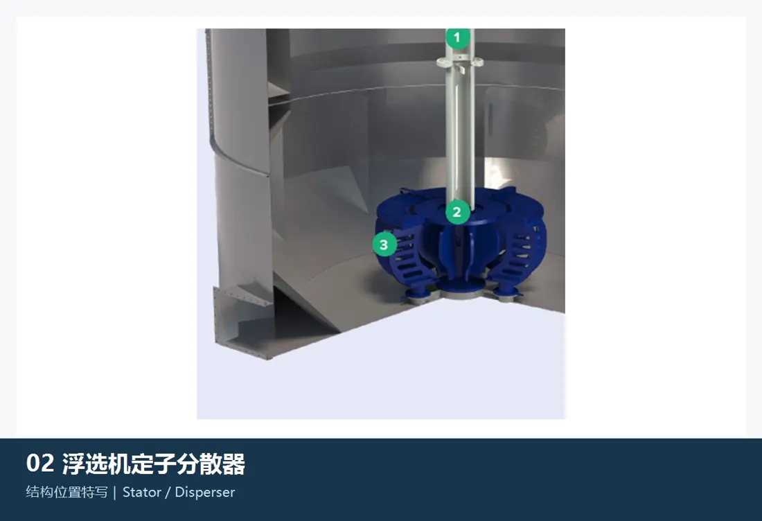
02

Stator / Disperser

Stator / Disperser

Applicable design: WEMCO II disperser / nextSTEP stator

nextSTEP uses a matched stator; WEMCO II uses a disperser. Their functions, designs and positions differ. Check series, volume, blade/window profiles, base holes, clearances, rotation and rotor pairing references.

Material and manufacturing checks: Confirm elastomers, polyurethane or original composites against abrasion, tearing, reagent compatibility and mating clearances.

View the Component Page →
Disperser Hood / Rotor Hood — design and position in FLS flotation equipment
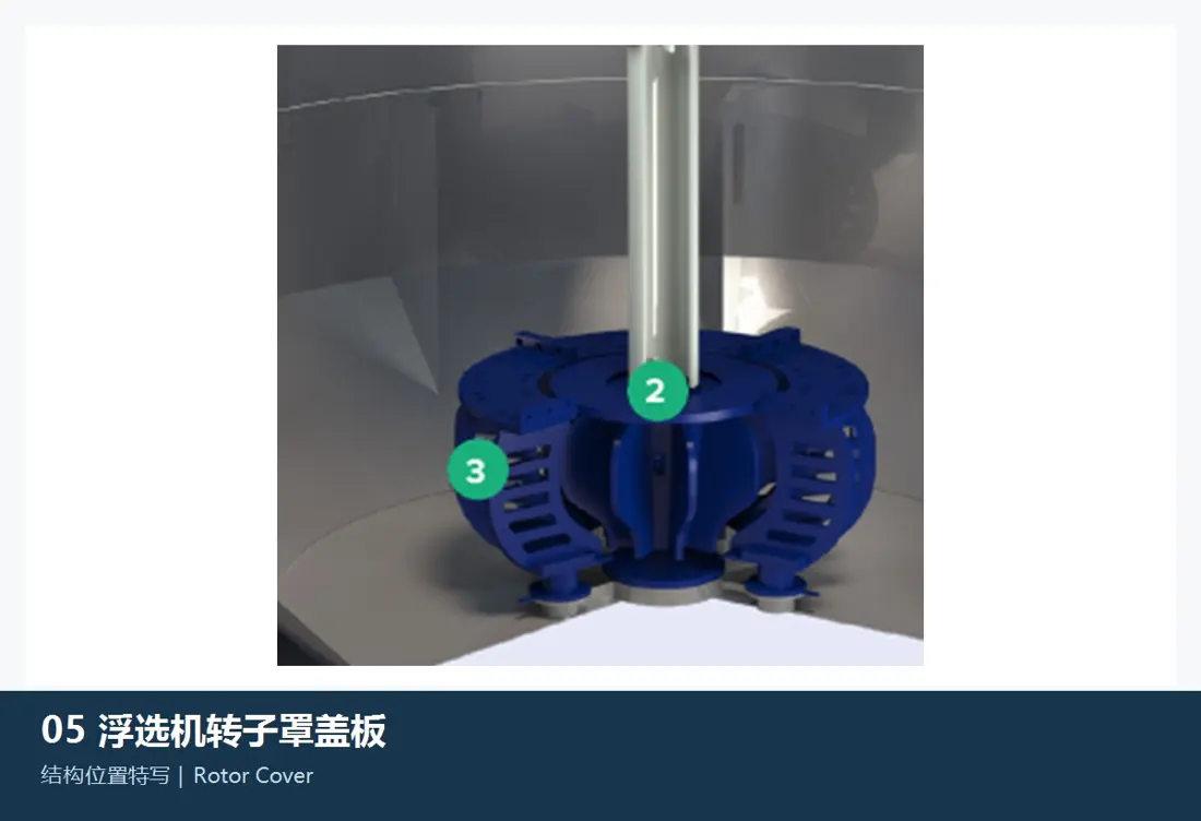
03

Disperser Hood / Rotor Hood

Disperser Hood / Rotor Cover

Applicable design: Installed WEMCO II / WEMCO 1+1 designs

Primarily for WEMCO self-aspirating designs, forming air/slurry circulation paths and protecting the wet end. Check WEMCO generation, volume, hood profile, windows, flanges, supports and disperser/rotor clearances.

Material and manufacturing checks: Confirm rubber or polyurethane coverings against abrasion, fatigue, reagent compatibility and moulded dimensions.

View the Component Page →
False-Bottom Liners / Assemblies — design and position in FLS flotation equipment
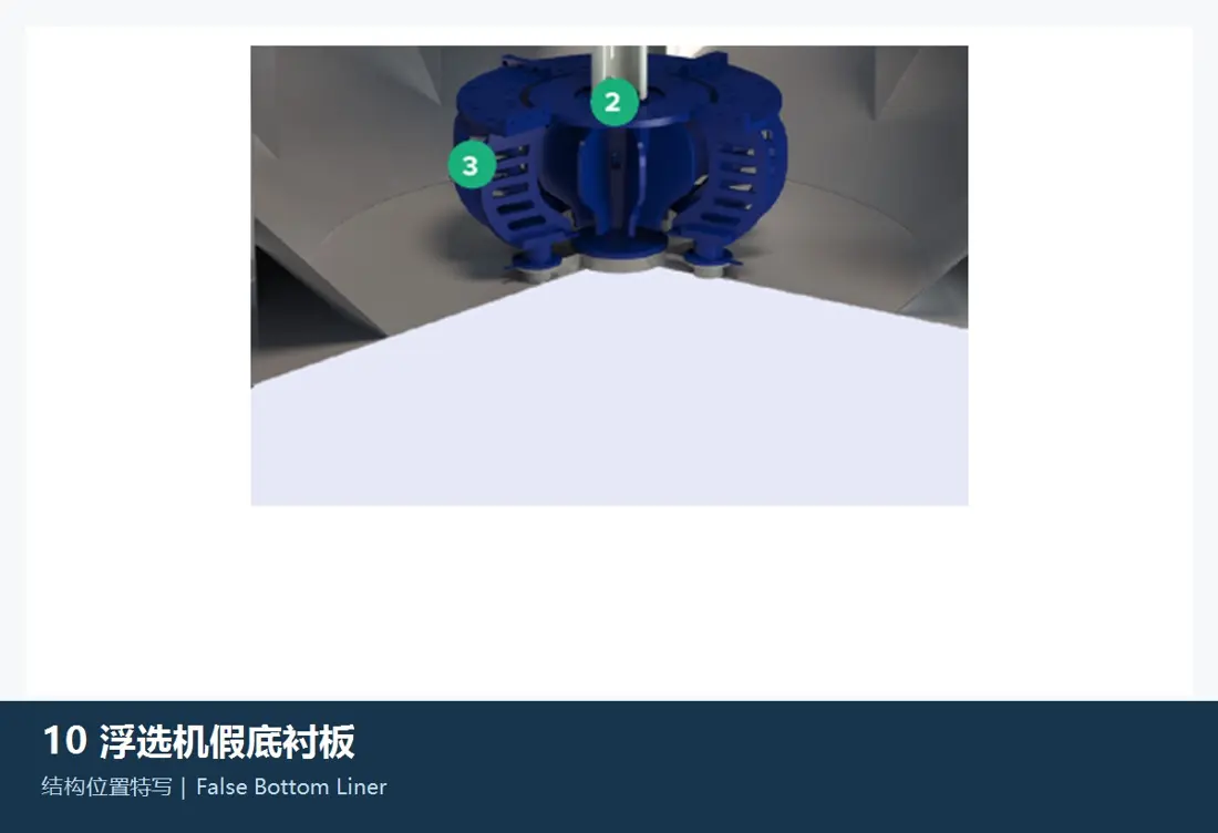
04

False-Bottom Liners / Assemblies

False Bottom Liner / False Floor

Applicable design: Installed WEMCO II / WEMCO 1+1 designs

Primarily for WEMCO self-aspirating cells, directing bottom slurry recirculation and protecting the floor. Check tank form, segmentation, thickness, holes, overlaps, flow boundaries and draft-tube clearances.

Material and manufacturing checks: Select rubber, polyurethane, corrosion-resistant steel or composite linings by slurry abrasion, reagents, temperature and structural stiffness.

View the Component Page →
Draft Tube / Standpipe Linings — design and position in FLS flotation equipment
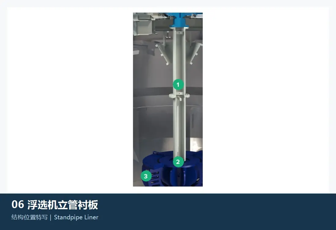
05

Draft Tube / Standpipe Linings

Draft Tube / Standpipe Liner

Applicable design: Installed WEMCO II / WEMCO 1+1 designs

Primarily for WEMCO self-aspirating designs, linking the false-bottom area to the upper rotor circulation path. Check diameter, length, flanges, supports, lining thickness, concentricity, rotor clearance and tank interfaces.

Material and manufacturing checks: Confirm rubber, polyurethane or corrosion-resistant alloys against slurry erosion, reagents, bonding method and dimensional stability.

View the Component Page →
Tank Liners — design and position in FLS flotation equipment
06

Tank Liners

Cell / Tank Liner

Applicable design: Verify separately against WEMCO / nextSTEP / Column / RFC drawings

Protect mechanical cells, flotation columns or local high-wear areas. Check series, tank shape, installation zone, segmentation, thickness, holes, seams, access doors and clearances to internals.

Material and manufacturing checks: Select rubber, polyurethane, corrosion-resistant steel or composite linings by slurry abrasion, corrosion, reagents and cleaning conditions.

View the Component Page →
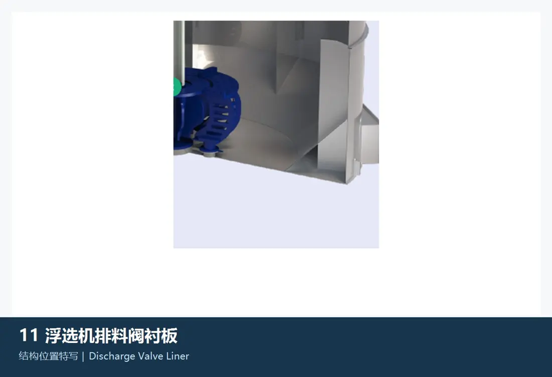
Discharge Valve Wet-End Liners — design and position in FLS flotation equipment
07

Discharge Valve Wet-End Liners

Discharge / Dart Valve Wet-end Liner

Applicable design: Mechanical cells / mixedROW; valve type determined by drawings

Protect slurry-contact surfaces of inter-cell discharge, level-control or underflow valves. Check valve type, cell position, bore, stroke, sealing surfaces, guides, actuator interfaces and flow direction.

Material and manufacturing checks: Select rubber, polyurethane, ceramic or corrosion-resistant alloy according to pressure differential, abrasion, reagents and sealing requirements.

View the Component Page →
Spare parts

Drive Shafts, Hubs, BHSA and Froth Skimmers

Drive and load-bearing parts require checks of interface accuracy, rotation, speed, air passages, bearings and seals together with the corresponding mechanical design and cell volume.

Rotor Drive Shaft and Sleeves — design and position in FLS flotation equipment
01

Rotor Drive Shaft and Sleeves

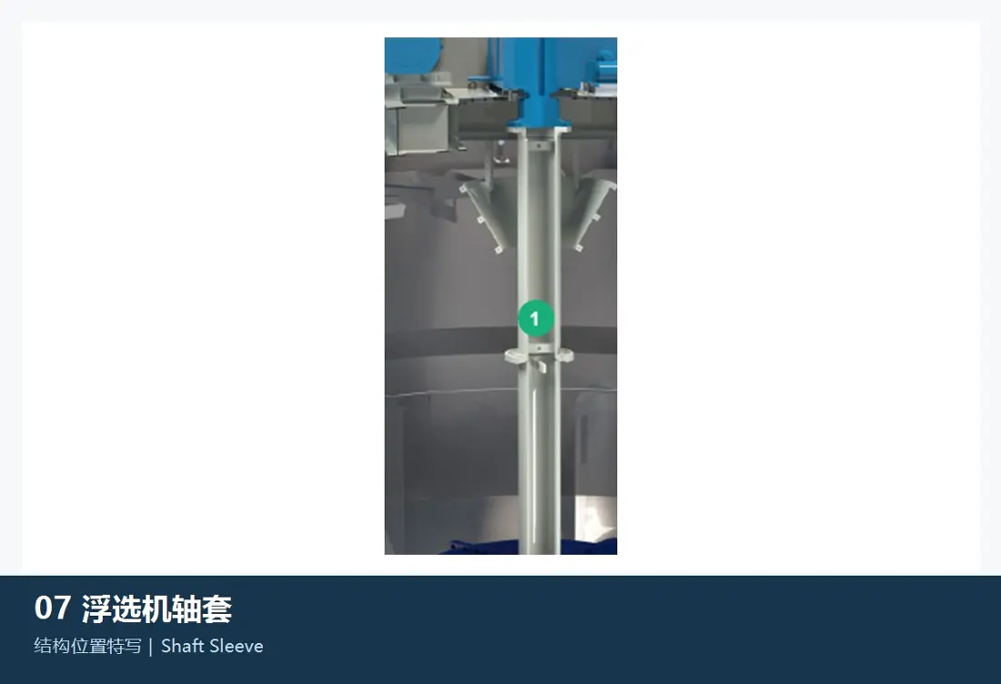
Rotor Drive Shaft and Sleeve

التصميم المطبق: مواضع خلايا WEMCO II / nextSTEP / mixedROW المقابلة

Transmit torque from the drive to the wet end. Check WEMCO or nextSTEP design, length, shaft diameters, hollow air passage, keys/splines, flanges, bearing and seal seats, rotation and dynamic balance.

Material and manufacturing checks: Consider forged alloy steel, stainless steel or the original surface protection. Verify heat treatment, journal accuracy and non-destructive testing against drawings and alternating loads.

View the Component Page →
محور الدوار / Connection Mount — design and position in FLS flotation equipment
02

محور الدوار / Connection Mount

محور الدوار / Mounting Hub

Applicable design: Mechanical flotation mechanisms

Connect the drive shaft to the rotor or wet-end assembly. Check bore, keys/splines, taper, flange, bolt holes, locating faces, rotation, fits and assembly access.

Material and manufacturing checks: Confirm drive alloy steel or corrosion-resistant alloy, heat treatment, dimensional accuracy and corrosion protection against torque, slurry conditions and original drawings.

View the Component Page →
Bearing Housings, المحامل والموانع — design and position in FLS flotation equipment
03

Bearing Housings, المحامل والموانع

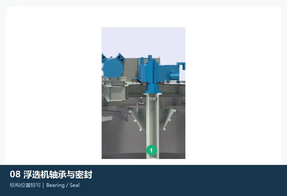
BHSA / Bearing and Seal

التصميم المطبق: مواضع خلايا WEMCO II / nextSTEP / mixedROW المقابلة

FLS lists bearing housing and shaft assemblies (BHSA) in its spare range. Check mechanism type, bearing designation, clearance, shaft/housing fits, seals, lubrication, speed, load and installation elevation.

Material and manufacturing checks: Confirm bearing steel, drive alloy steel and oil/chemical-resistant seals by loads, temperature, slurry, lubrication and original designations.

View the Component Page →
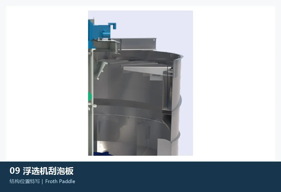
Froth Paddles / Skimming Mechanisms — design and position in FLS flotation equipment
04

Froth Paddles / Skimming Mechanisms

Froth Paddle / Skimmer

Applicable design: Optional WEMCO II designs and other cells with froth skimmers

Mechanically assist recovery of thin or slow-moving froth. Check cell type, paddle length, diameter and count, rotation, shaft, chain/gear drive, speed, supports and launder interfaces.

Material and manufacturing checks: Select stainless steel, engineering plastics or rubber-covered designs by corrosion, froth, weight and cleaning conditions.

View the Component Page →
Drawing and Spare-Part Numbers

Match OEM or Third-Party References to Series, Cell Position and Design

With any reference, provide the full series, cell volume, serial number, cell position, WEMCO/nextSTEP/RFC design, part name, drawings, used-part photographs, key dimensions, material and slurry conditions.

Are WEMCO II and nextSTEP rotors, dispersers or stators interchangeable?

No. Air supply, rotor position and profile, matching disperser/stator, base plates and clearances differ. Verify the full series, cell volume, serial number and drawings.

Can mechanical-cell parts be used in Column, REFLUX RFC and coarseAIR units?

No. They use external aeration, inclined-channel/pressure-chamber or coarse-particle designs respectively. Identify spares from their own piping, valves, tanks and project drawings.

Send the FLS Flotation Series, Cell Volume, Drawings or Spare Requirements

Provide the full series, cell volume, serial number, cell position, OEM/third-party references, drawings, used-part photographs, key dimensions, material and slurry conditions. These support identification, material assessment, production at certified foundries, quality control and finished-part delivery.

Send التفاصيل for a Quotation

رقم الهاتف: +86 156 3797 3199
zzx@anranst.com

خدمات صنع في الصين

من التقييم الفني إلى تسليم المنتج بالكامل

توفر شركة ANRANST للعملاء العالميين تقييمات هندسية، واختيار التصنيع الصيني، ومراقبة الجودة، وتسليم الأجزاء النهائية لقطع الغيار الصناعية المقاومة للتآكل حسب الطلب، ويمكنها أيضًا دعم قطع الغيار الصناعية الأخرى حسب الطلب.

01

مراجعة الرسومات والهندسة

قم بمراجعة أسطح التزاوج وأبعاد الواجهة، وقم بتقييم جدوى المواد والمعالجة الحرارية والتصنيع.

02

تحديد المادة والمعالجة الحرارية

تُحدَّد درجات المواد وعمليات المعالجة الحرارية لكل طلب على حدة، وتُثبَّت في الاتفاقية الفنية وتُتابَع أثناء الإنتاج.

03

ضبط الجودة

يشمل ذلك تأكيد الرسم، ومراقبة المواد والعمليات، وتتبع الإنتاج، وتنسيق عمليات الفحص والقبول.

04

تسليم المنتج النهائي

تنظيم عمليات التصنيع والتحقق من الجودة والتعبئة والتغليف وتسليم المنتجات النهائية الكاملة لتشكيل حلقة إمداد قابلة للتنفيذ.

قم بتزويدنا بالنماذج الحالية، والرسومات، وأرقام الرسومات، وأرقام الأجزاء، والمواد، أو معلومات ظروف التشغيل، وسنقوم بتحديد التحقق الفني ومسار التوريد وفقًا لذلك.

إرسال طلب