Metso Nordberg C Series Jaw Crushers

Identification and supply of jaw plates, cheek plates, shaft assemblies, bearings, adjustment mechanisms and dedicated service tools for C80–C200 and C3054 installations.

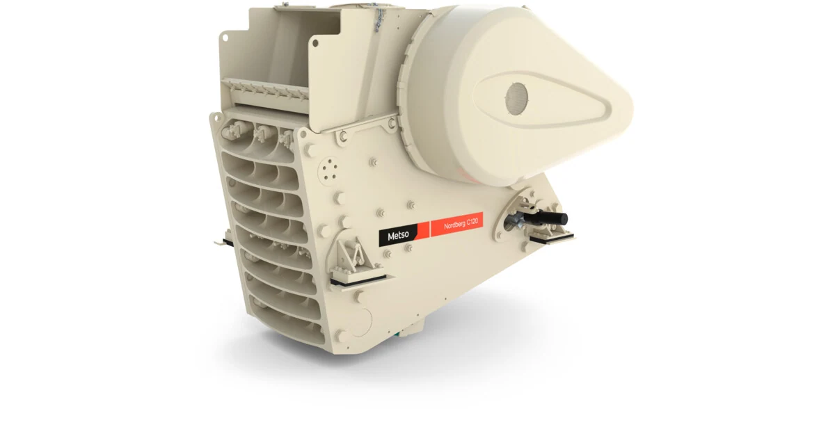
Metso Nordberg C120 jaw crusher
Nordberg C120 crusher showing the drive, frame and adjustment system configuration.
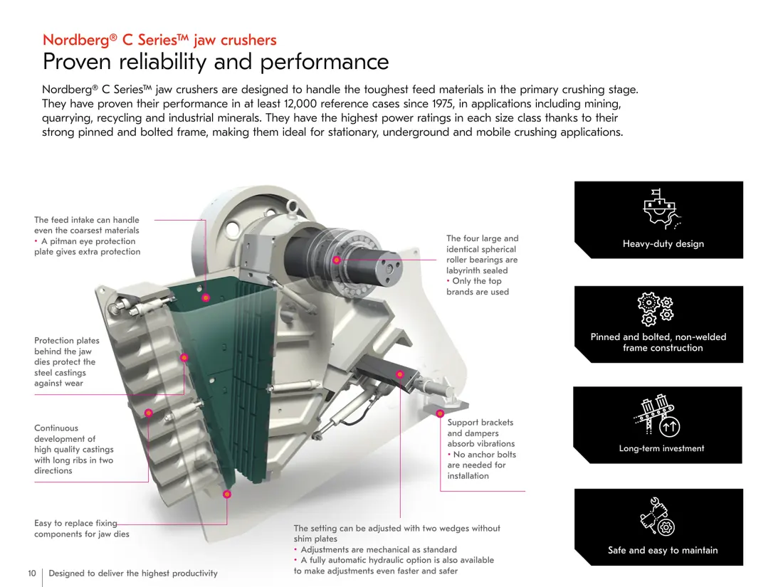
Nordberg C Series jaw crusher cutaway
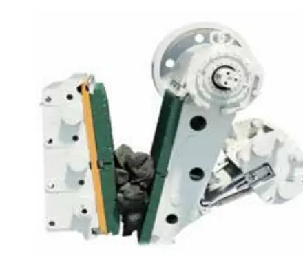
C Series cutaway showing the jaw plates, pitman, eccentric shaft, bearings and adjustment area.
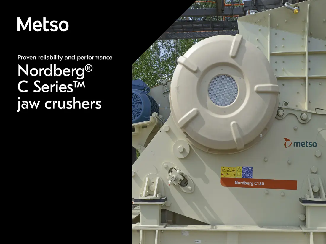
Metso Nordberg C130 Jaw Crushers
Nordberg C130 on site, showing the machine, frame and drive side for identification.
OEM Equipment Series

Identify Parts by Complete Model, Crushing Chamber and Jaw Tooth Profile

C Series parts matching depends on more than the crusher model. Fixed or movable side, one-piece or two-piece construction, tooth profile, discharge setting, adjustment system and drawing revision can all affect the model details and assembly fit.

10Current Standard Models
800–2000 mmFeed Opening Width
75–400 kWMaximum Installed Power
13,000+Worldwide Installed Base
Standard Models and Key Dimensions

Nordberg C Series Model Range

Feed opening, estimated maximum feed size, speed and power help identify the installed machine.

Standard ModelsFeed Opening (Width × Depth)Estimated Maximum Feed SizeSpeedMaximum Installed Power
C80800 × 510 mm410 mm350 rpm75 kW
C96930 × 580 mm460 mm330 rpm90 kW
C1061060 × 700 mm560 mm280 rpm110 kW
C1171150 × 760 mm610 mm260 rpm132 kW
C1201200 × 870 mm700 mm230 rpm160 kW
C1301300 × 1000 mm800 mm220 rpm185 kW
C1501400 × 1200 mm960 mm220 rpm200 kW
C1601600 × 1200 mm960 mm220 rpm250 kW
C2002000 × 1500 mm1200 mm200 rpm400 kW
C30541380 × 760 mm610 mm260 rpm160 kW
Estimated maximum feed size refers to the intermediate dimension of a lump with new jaw plates fitted. Actual feed opening depth depends on the crushing chamber. Manufacturing jaw plates and spare parts requires confirmation of the drawing, tooth profile, fixed or movable side and drawing revision.
Metso

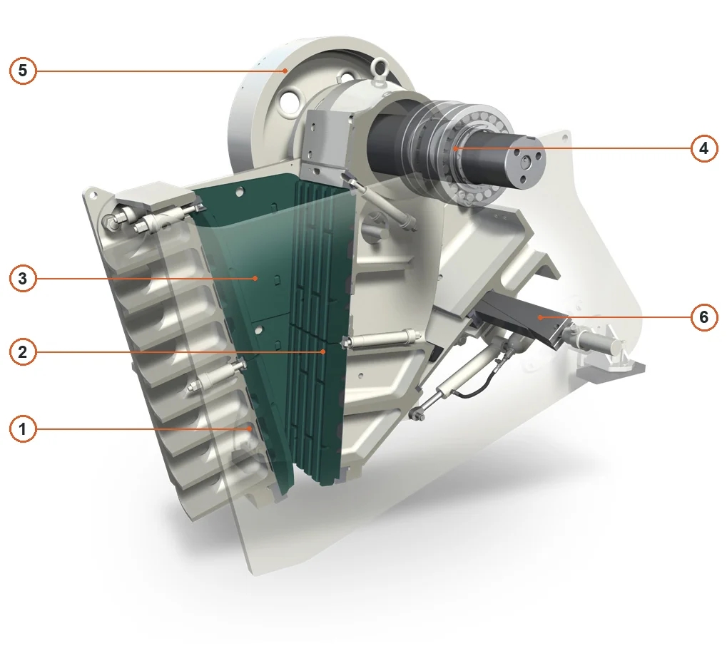
Component Location Diagram

The numbers on the diagram correspond one to one with the rows below.

Metso Nordberg C Series Jaw Crushers – Component Location Diagram
No.ComponentLocationApplies to
1Fixed jaw dieFixed crushing face on leftNordberg C Series
2Movable jaw dieMovable crushing face on rightNordberg C Series
3Cheek plateSide wall between jaw diesNordberg C Series
4Spherical roller bearingCutaway bearing at upper shaft endNordberg C Series
5FlywheelUpper rear flywheelNordberg C Series
6Adjustment wedgeAdjustment wedge behind lower movable jawNordberg C Series
Wear Parts

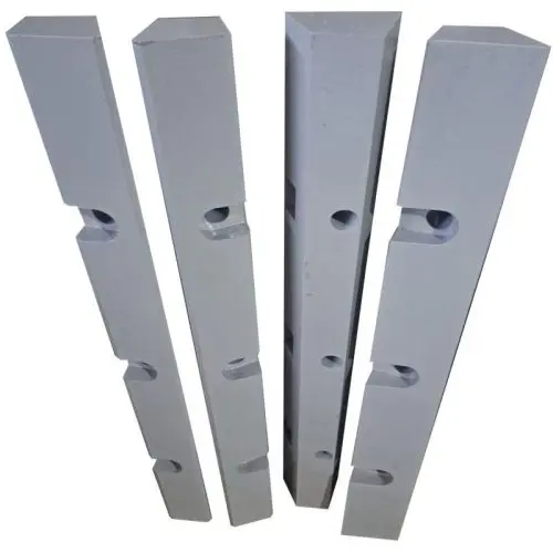
Crushing Chamber Jaw Plates and Frame Protection

Open general part pages by installation position, then match tooth profile, material and wear duty to the specific C Series machine.

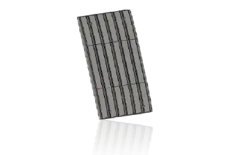
C Series Intermediate Plates
05

Intermediate Plates and Protection Plates

Intermediate & Protection Plates

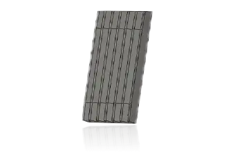
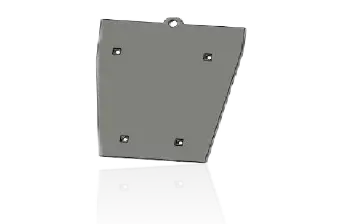
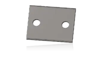
Intermediate plates adjust crushing chamber geometry; protection plates reduce wear behind the jaw plate on the frame. Check each separately for model, position, thickness, profile and fit with jaw retention parts.

View general intermediate plate guidance →
Jaw Plate Part Numbers

One-Piece Jaw Plate Profiles and Part Numbers

The numbers below distinguish model, tooth profile and movable or fixed side. Include the installed model details and drawing revision with your enquiry.

Model Tooth Profile Movable Jaw Plate (swing side) No. Fixed Jaw Plate (stationary side) No.
C110 Quarry N11918208 814391312500
C120 Quarry MM0586425 MM0585542
C125 Quarry N11954353 N11954343
C130 Quarry MM1031742 MM1086204
C140 Quarry MM0218048 MM0218047
C145 Quarry MM0226278 MM0226277
C150 Quarry MM1110178 MM1004104
C160 Quarry N11924296 N11924295
C110 Super grip + Quarry MM0534103 814391312500
C120 Super grip + Quarry MM0588282 MM0585542
C125 Super grip + Quarry MM0285590 N11954343
C130 Super grip + Quarry MM1071843 MM1086204
C140 Super grip + Quarry MM0404574 MM0218047
C145 Super grip + Quarry MM0226707 MM0226277
C150 Super grip + Quarry MM1011873 MM1004104
C160 Super grip + Quarry MM0219198 N11924295
C110 Superteeth 1046590661 1046590660
C120 Superteeth MM0588450 MM0588449
C125 Superteeth 1046590663 1046590664
C160 Superteeth N11953473 N11953466
C110 MX MM0376278 MM0376280
C120 MX MM1103860 MM1103600
C125 MX MM1031938 MM1031747
C140 MX MM1122242 MM1122241
C106 Coarse corrugated 10141771001 10141770001
C110 Coarse corrugated 10140674001 10140672001
C120 Coarse corrugated 10141449001 10141448001
C125 Coarse corrugated 10182881001 10182879001
C140 Coarse corrugated 10217071001 10217070001
C160 Coarse corrugated 10141524001 10141523001

Part numbers identify parts but do not establish interchangeability. Confirm model, fixed or movable side, tooth profile, one-piece or two-piece construction, thickness and drawing revision before quotation. The OEM table notes that the C110 MX fixed jaw MM0376280 is 22 mm thicker than the regular version, reducing maximum closed-side setting.

Spare Parts

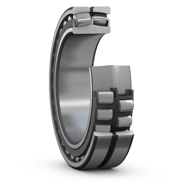
Pitmans, Eccentric Shafts, Bearings and Adjustment Systems

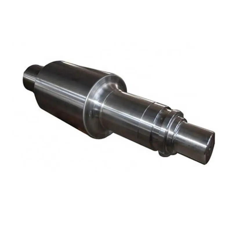
Check shaft diameters, fits, accuracy, heat treatment, lubrication, installed configuration and drawing revision separately for drivetrain and load-bearing parts.

FAQ

Frequently asked questions

What information is needed to enquire about C Series jaw plates?

Provide the complete model, fixed or movable side, one-piece or two-piece construction, tooth profile, drawing, current part photographs, material and crushing conditions.

Does knowing C120 or C130 identify the jaw plate number?

No. A single model may use different tooth profiles, fixed or movable plates, one-piece or two-piece designs and drawing revisions. Check the installed model details or equipment drawings.

What materials are typically used for C Series jaw plates?

Jaw plates are generally based on manganese steel. The alloy, tooth profile and heat treatment must be selected for the rock type, abrasiveness, feed size and impact conditions.

Send Your Nordberg C Series Model, Jaw Plate Number or Spare Part Drawing

Provide the complete model, serial number, nameplate, installation position, photographs of the current part, drawings, material and operating conditions. We use these to identify the part, assess materials, organize production at certified foundries, coordinate quality control and arrange finished-part delivery.

Equipment Brand and ModelDrawingDrawing or DimensionsCurrent MaterialPhotographs of Failed PartsTarget Service LifeOperating Conditions
Request a Quote

Or contact us directly: +86 156 3797 3199
zzx@anranst.com

Manufacturing Services in China

From Technical Assessment to Finished-Part Delivery

ANRANST provides customers worldwide with engineering assessment, production at certified foundries to the customer technical requirements, quality control and finished-part delivery for custom wear parts and industrial spares, with scope to support other custom industrial parts.

01

Drawing and Engineering Review

We review mating surfaces and interface dimensions and assess material, heat treatment and manufacturing feasibility.

02

Material and Heat-Treatment Specification

Material grades and heat-treatment processes are specified order by order, stated in the technical agreement and tracked through production.

03

Quality Control

Drawing confirmation, material and process control, production tracking, inspection and acceptance coordination.

04

Finished-Part Delivery

We coordinate manufacturing, quality confirmation, packaging and delivery of complete finished parts in a workable, closed-loop supply process.

Provide the existing model, drawings, drawing, materials or operating conditions so we can identify the appropriate technical review and supply route.

Submit an Enquiry