CITIC HICSemi-mobile Crushing Stations

From Item Name, built-in crusher and system Configuration Enter the stall, Apron Feeder Transit Liners traction, dragging Power Transmission and RFQ.

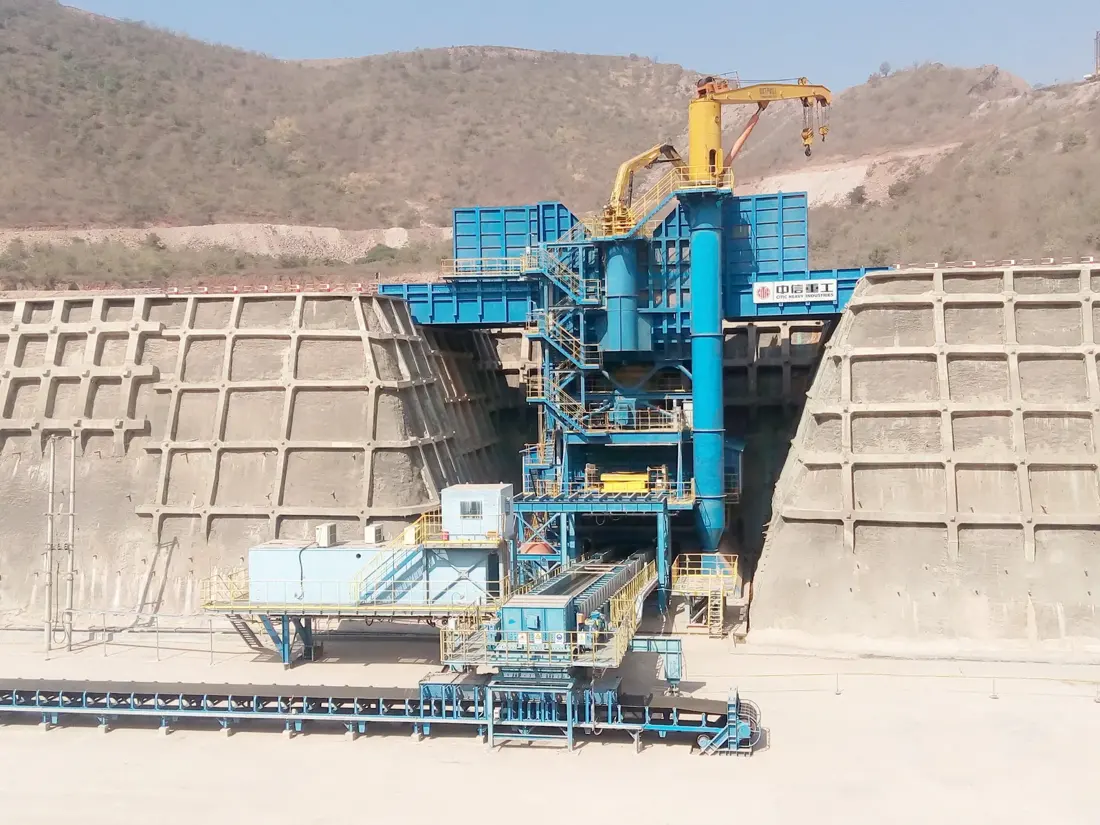
CITIC Heavy Industries Semi-Mobile Crushing Stations Official Product Picture
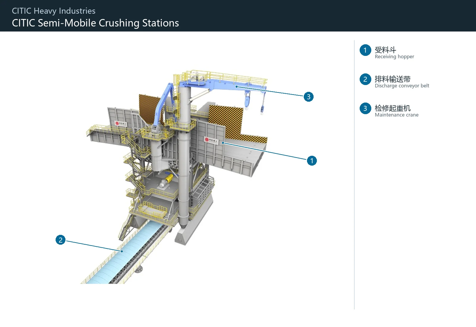
CITIC Heavy Industries Official Semi-Mobile Crushing Stations Product diagrams; specific installers Item Name, Lord Model Number, feeds and transmission systems documents confirmed.
OEM Equipment Details

by Item System rather than fiction Standard Models Identification

Semi-mobile crushing station is a project type set of equipment. This page identifies the items, built in broken mainframes and feeder hopper systems as well for board feeding machines or transshipment system before entering corresponding wear parts to drive Spare parts & materials pages

Item Types of Equipment Properties
3 Core System
12 wear parts and spare parts Entrance
1 Technical Enquiry
Standard Models and Key Dimensions

Item Configuration and Cores Identification Fields

The crushing station does not have a uniform model table that can be directly applied from the project file. First, confirm projects and built-in hosts to check feeds / delivery systems for fuelwood or transshipment configuration

System LevelsNeeds to be provided Identification informationKey dimensions / ConfigurationEntering the Technology Pathways
Semi-Mobile Crushing Stations ItemItem Names, general arrangement drawing, station number Equipment List ofProcessing volume, maximum feedstocks and layout & high-qualityConfirming the entire border and Drawing Revision
Built-in crushing consoleBrands, complete model, serial number, Hosts drawing numberFeed opening, closed-side setting, cavity profileEntering correspondence Gyratory Crusher Other Broken Host Pages
Supply and Transit SystemsApron Feeder model, conveyors and slipper drawingsWidth, sizing distance and centering range InterfacesEnter the feeder, foil and slot parts page

Manufacturing and quotation Must have parts Relatively to specific Item system, Equipment Number of digits, installation position and Drawing Revision "Can't just write." Semi-Mobile Crushing Stations spare parts ”.

Wear Parts

Abrasion systems for the hopper, feed and transshipment areas

Expand according to the impact area of a hopper, side wall in an outlet and tails from feeder machines; different locations shocking abrasive wear Differently, materials Determinations separately.

Category: Submerged hoppers Liners Identification Figures
01

Category: Submerged hoppers Liners

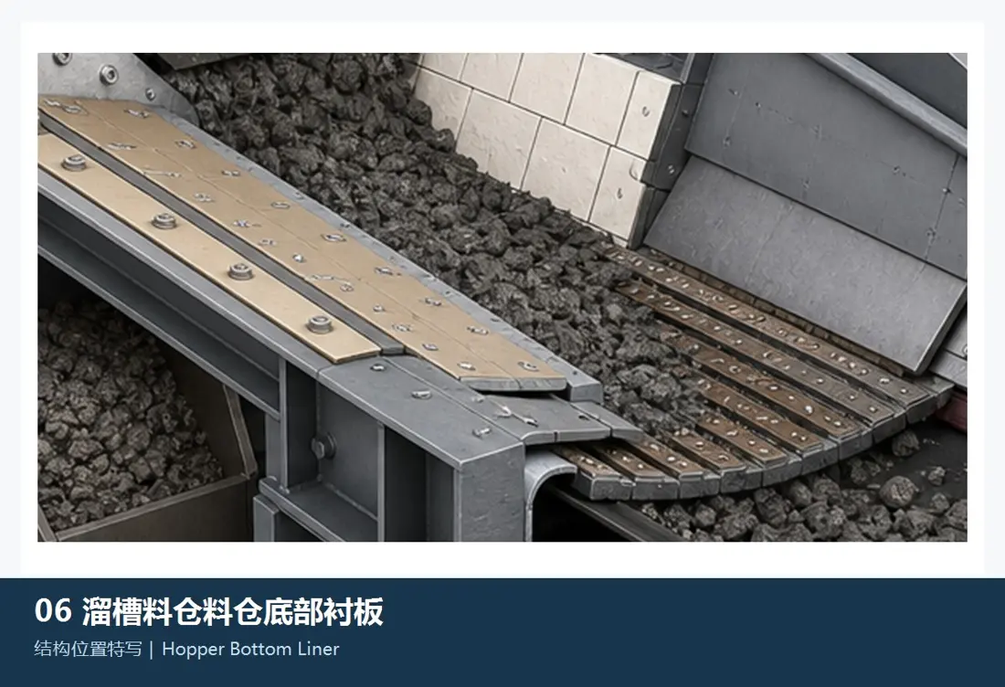
Hopper Bottom Liner

Protection of high impact and wear areas at the bottom. Converging between scattering, profile size plate thicknesses; hole lines: bearing surfaces - precipitation height as well for large ore shock directions

Material Selection: Quenched and Tempered Wear Plate, high-manganese steel, double-metal or Composite liners By impact, abrasive wear, plate thickness and replacement method confirmed.

View Part Details →
Category: Shock Zones Liners Identification Figures
02

Category: Shock Zones Liners

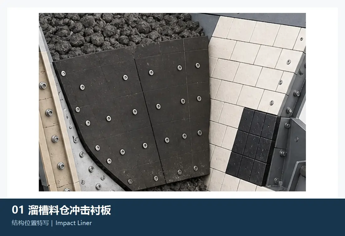
Impact Liner / Wear Plate

Mounting In the area of direct impact. Contrasts shock center, plate lining and thicknesses; backboarding: fixed mode as well with field crack or deformation records

Material Selection: high-manganese steel, Quenched and Tempered Wear Plate Or ability backplane complex Construction Confirm by the proportion of large block impact and wear.

View Part Details →
Chute Side Liners Identification Figures
03

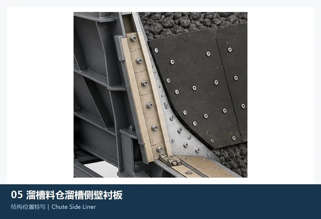
Chute Side Liners

Chute Side Liner

Protection of the side wall flowing area in a transshipment scooter. Contrast to left-hand direction, sloped position and surface surfaces with thicknesses on board plates; hole lines for connecting or material flows

Material Selection: Quenched and Tempered Wear Plate, high-chromium cast iron, ceramic or Composite wear-resistant construction At impact, speed and abrasive wear Confirmation.

View Part Details →
Apron Feeder side liners Identification Figures
04

Apron Feeder side liners

Apron Feeder Side / Skirt Liner

Locations Apron Feeder On both sides, the material spill is limited and side walls are protected. The gaps between them can be determined by a vertically-right direction of length; plate thicknesses or holes in each other as well than adjacent groove plates with respect to one another'S surface area (see enclosure).

Material Selection: Quenched and Tempered Wear Plate Or composite wearables plate sliding wear, shocks and welding methods are confirmed.

View Part Details →
Apron Feeder tail Feed Liners Identification Figures
05

Apron Feeder tail Feed Liners

Tail Inlet Liner

The tail of the feeder is protected from both a scattering and large impact areas. Contrast plate layout, outline size thicknesses; hole lines: drop point level (SC) or operating gap with slot board

Material Selection: Manganese steel or quenched and tempered abrasion-resistant plate By impact, abrasive wear and Installation Confirmation.

View Part Details →
Head Discharge Chute Liners Identification Figures
06

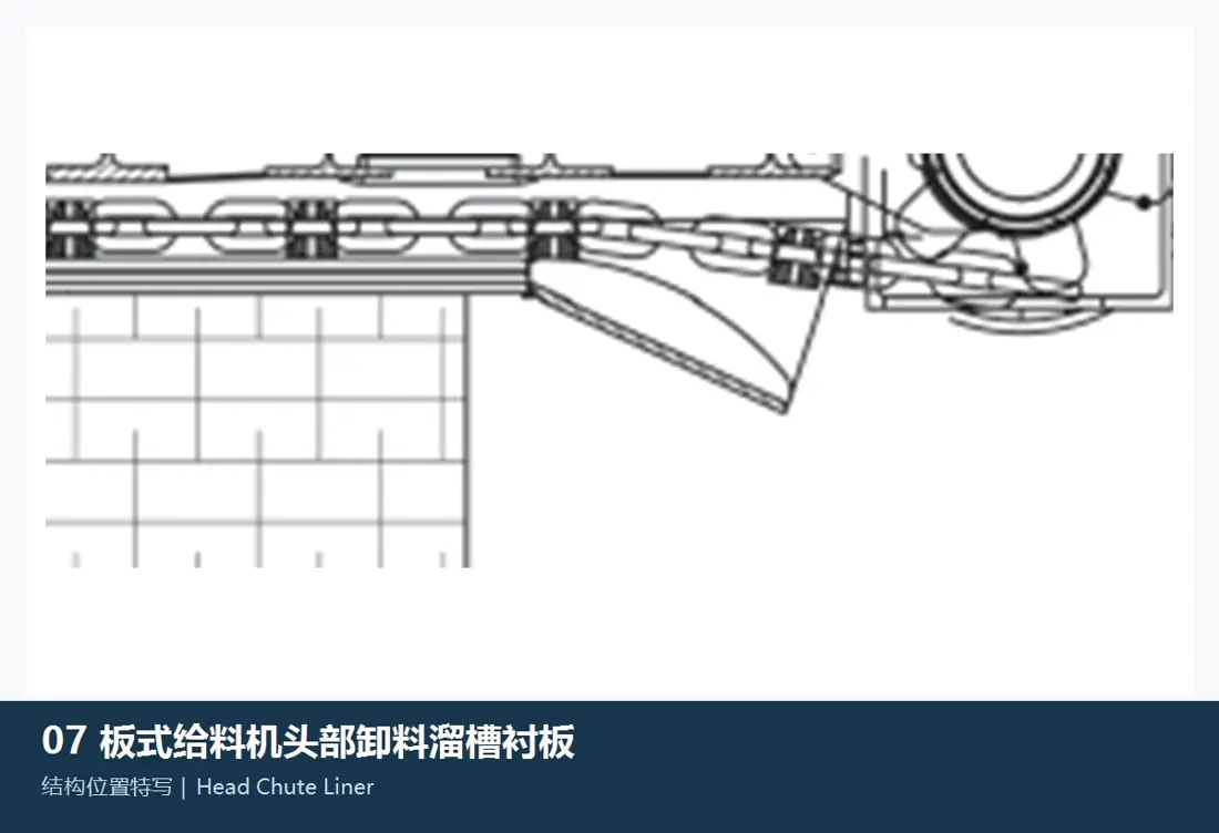
Head Discharge Chute Liners

Head Discharge Chute Liner

Protection Apron Feeder Head drain and transshipment area. Converging material tracks, fragments of the plate thicknesses / plates with surface surfaces or holes & downstream hosts Interfaces.

Material Selection: Quenched and Tempered Wear Plate, high-chromium cast iron or Composite liners Acknowledged by granularity, speed and impact conditions.

View Part Details →
Spare Parts

Apron Feeder Links and chains Power Transmission -, and the Sponsor spare parts

slate, chain-chain and cover boarding sprocket, Wheels and tensioning system by Item Feeding feed Model Number, spacing and widths; direction. materials and heat treatment Converging separately.

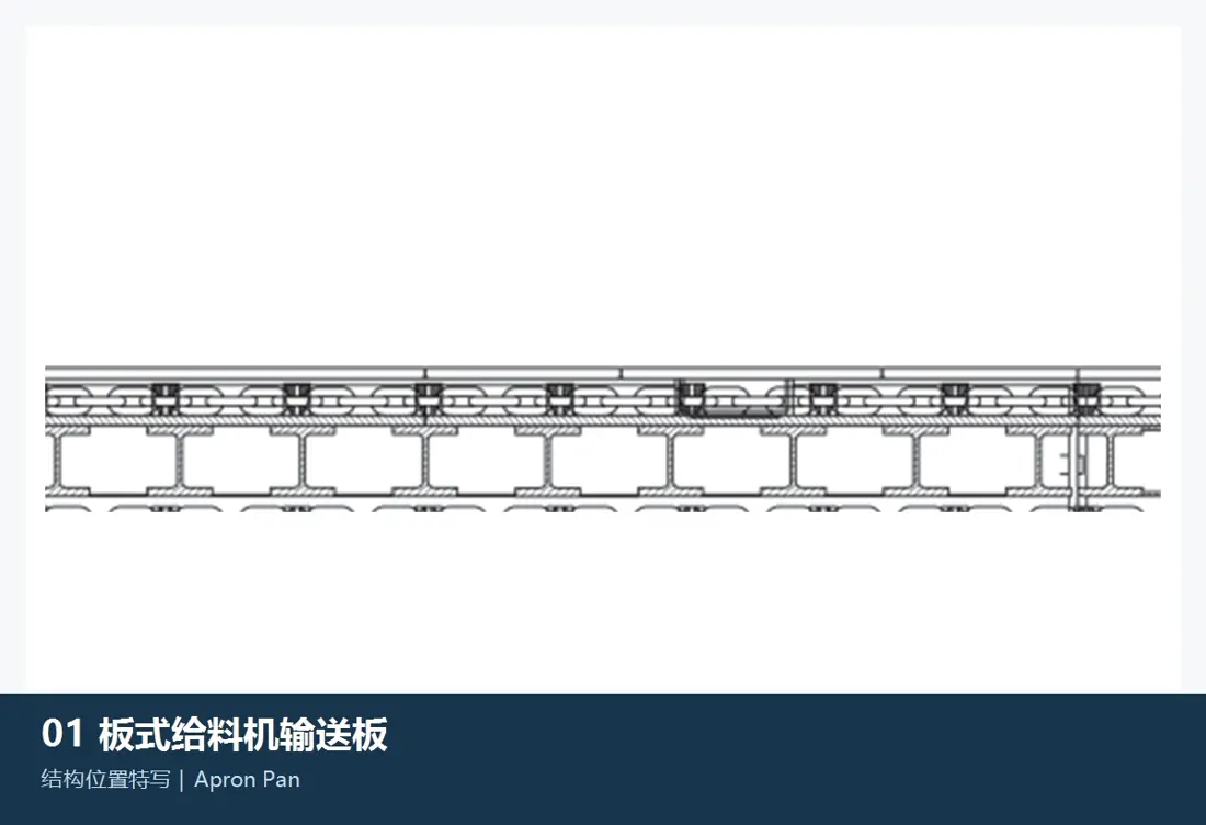
Apron Feeder scooter Identification Figures
01

Apron Feeder scooter

Apron Pan / Feeder Pan

The load and transport of large blocks ore: the width, spacings to be determined by thicknesses in plate size; connecting with a pairing hole for an earringhole on lineage Interfaces and the center of a complete car.

Material Selection: High-intensity Wear-Resistant Cast Steel or alloy steel Confirm by impact, bending and wear as well AS hinge loads.

View Part Details →
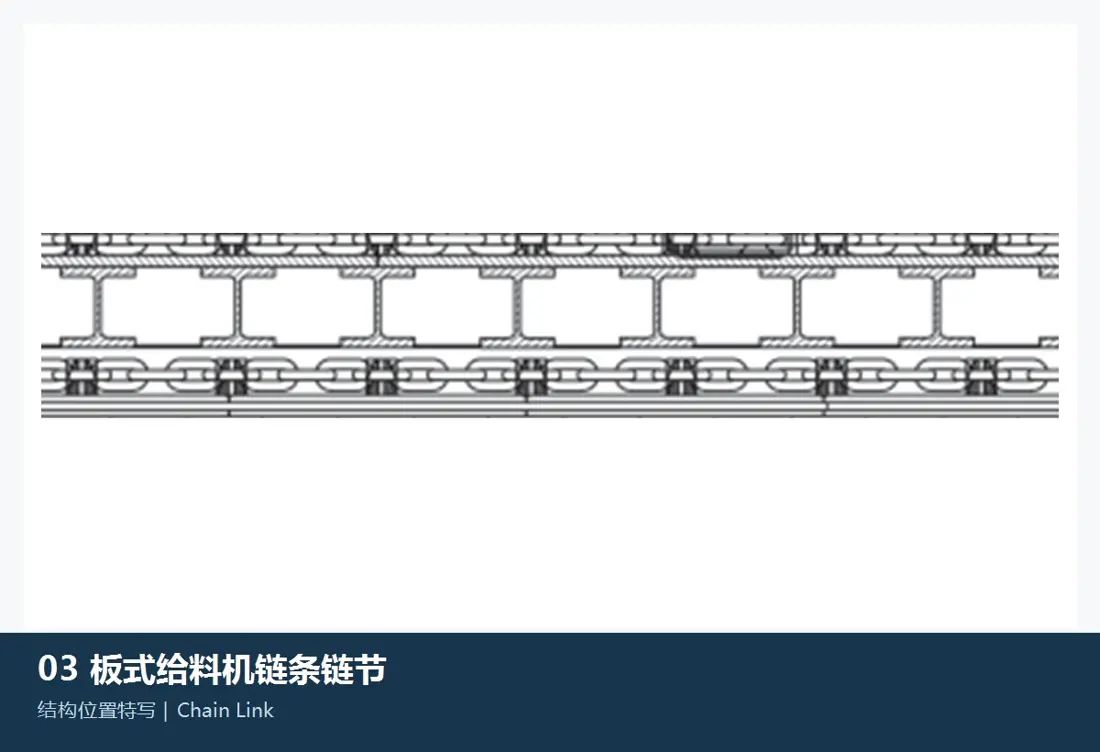
Links of Chain Identification Figures
02

Links of Chain

Chain Link

Passenger Apron Feeder traction. Contrast the spacing, aperture diameters and width of right-hand side parts; heat treatment and the fittings pins.

Material Selection: Forging or casting alloy steel, heat treatment and NDT Confirm by the requirements for traction loads, shock and fatigue.

View Part Details →
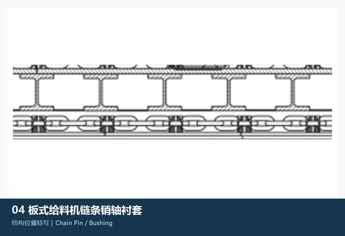
Links and bushings Identification Figures
03

Links and bushings

Chain Pin & Bushing

Forming a chain articulated and withstands surface pressure, swing or grinding intrusion. bushings Inner and External Paths, Length Flowing & Coupling heat treatment.

Material Selection: Carbon permeation, induction quenching or Quenched and tempered alloy steel Confirm by the surface pressure, toughness and wear resistance.

View Part Details →
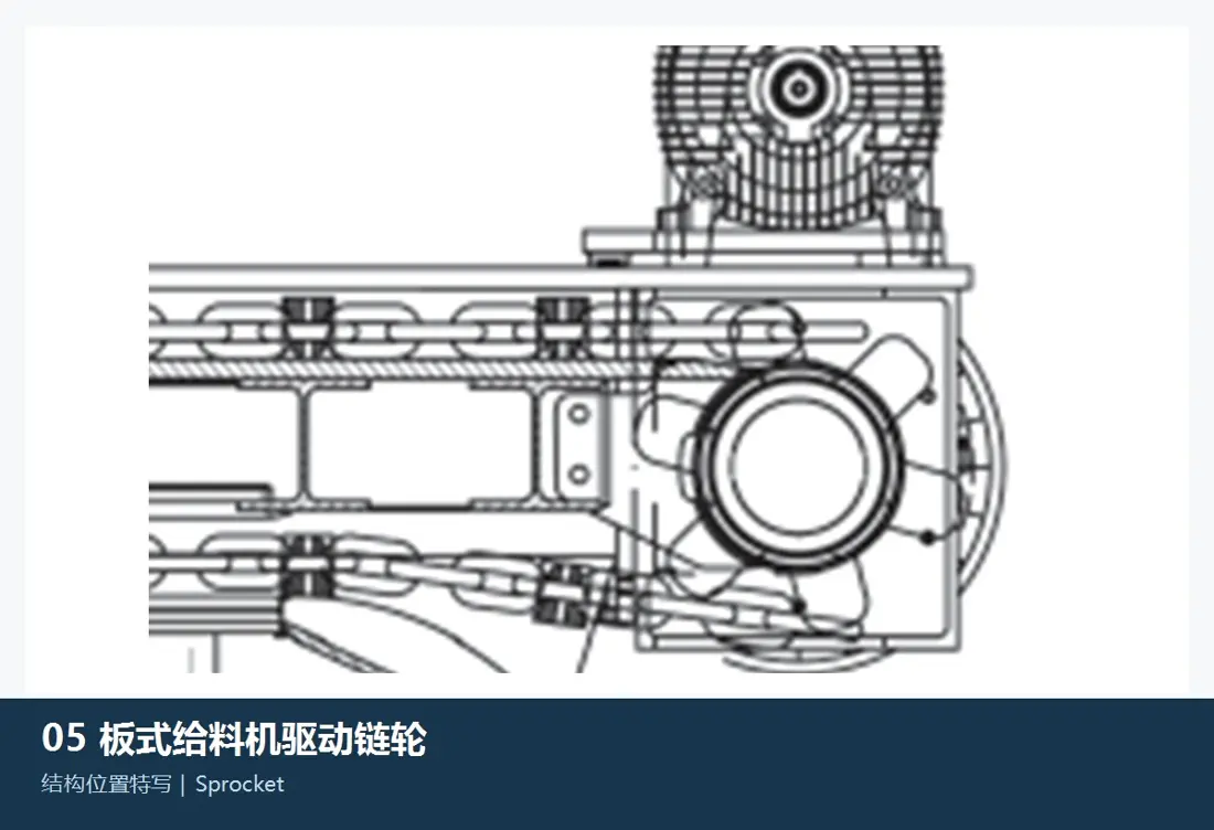
Drive Sprockets / Traction Wheels Identification Figures
04

Drive Sprockets / Traction Wheels

Sprocket / Traction Wheel

Drives to connect with the chain of dragging. Converged teeth number, spacing Tooth Profile, Wheels and Axes Interfaces, Left-handed direction and chain Wear condition.

Material Selection: Cast Steel or Forged Alloy Steel, toothed face heat treatment and machining accuracy by load, chain or original design.

View Part Details →
Heavy-duty wheel Identification Figures
05

Heavy-duty wheel

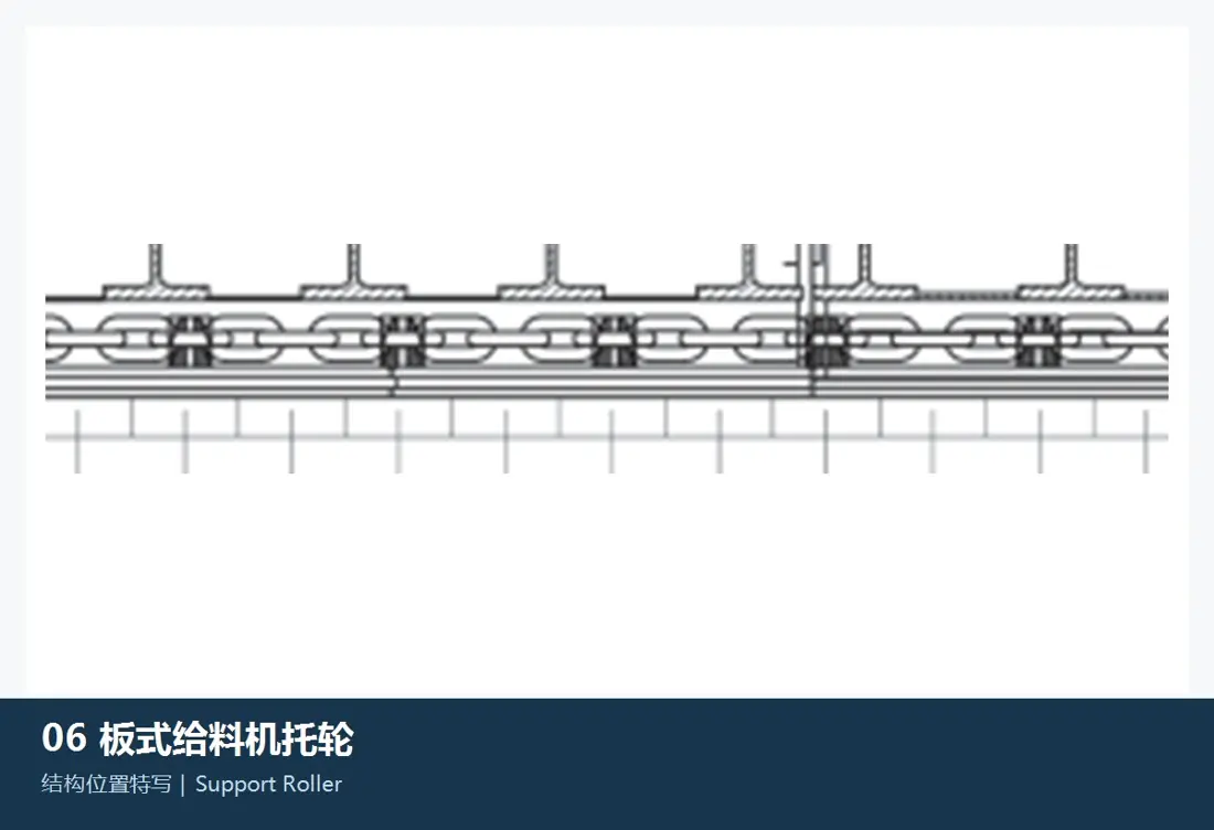
Support Roller

The scattering board and chain operation. Converging wheel diameter, width of the wheels or shaft neck bearing, sealing and Mounting Distance and orbital relationship.

Material Selection: alloy steel or Cast Steel Wheels, bearing and seals by loading, impacting / dust or the conditions of lube.

View Part Details →
Links tensioning system Identification Figures
06

Links tensioning system

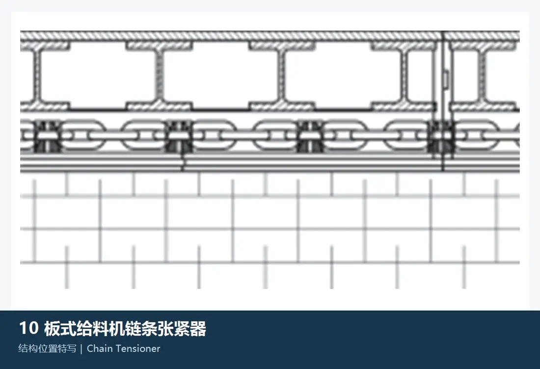
Chain Tensioner

Keep the traction chain to specify tension and operation center. Contrast itinerary, wire rod or hydraulic Construction, Mounting Interfaces, left-hand and adjustment range.

Material Selection: High-intensity Construction Pieces, screw sub- and hydraulic or Seals Recognize the load and original drawings.

View Part Details →
Drawing and Spare Part Numbers

Item Number of digits, OEM drawing number and third parties spare parts Node Confirmation Entry

Crusher Station spare parts Must be recorded simultaneously Item system, Equipment Number of digits and Drawing Revision No numbers of these contexts do not openly establish correspondence.

Selection Guidelines: Crusher Station Item Number of digits, OEM drawing number With third parties spare parts The column is saved; only published can be traced back to Item system, installation position Relativities with the original basis.

Why Semi-Mobile Crushing Stations Pages are ununified Standard Models ?

It is a system configured by mine project, with host and feeds to be delivered as well for the layout of projects; it must identify using inventory items equipment numeric numbers or drawings.

Only know the crushing station. Item Can the name be confirmed? parts ?

Item The name can be used as a starting point for retrieval, but Manufacturing Reconciliation is still required Equipment Numbers and built-in mainframe Model, drawing number, installation position, Drawing Revision and Key dimensions.

Can the feed groove board and chain be interchanged at a close width?

No. Requires check-in model, spacings and center distance; hinged holes. Interfaces directional, materials, heat treatment and the fittings sprocket.

Submission CITIC Heavy Industries Semi-Mobile Crushing Stations Item, Equipment Number of digits, drawing number or spare parts Demand

Provide project names, equipment lists and host models numeric numbers; drawings of used parts (materials) as well for operating conditions. We complete system identification with the result that we can evaluate materials in a way which ensures quality control over finished-part delivery

Manufacturing Services in China

From Technical Assessment to Finished-Part Delivery

ANRANST provides customers worldwide with coordinated consulting, supplier sourcing, quality control and finished-part delivery for custom parts, wear parts and industrial spares from China, with scope to support other custom industrial parts.

01

Technical Advice

Equipment and part identification, drawing review, material selection and manufacturing feasibility assessment.

02

Supplier Introductions

Match requirements with suitable manufacturers in China and coordinate the exchange of technical information.

03

Quality Control

Drawing confirmation, material and process control, production tracking, inspection and acceptance coordination.

04

Finished-Part Delivery

Coordinate manufacturing, quality confirmation, packaging and delivery of complete finished parts.

Provide the existing model, drawings, drawing or part numbers, materials or operating conditions so we can identify the appropriate technical review and supply route.

Submit an Enquiry