TAKRAF Heavy-Duty Apron Feeders

Use published widths, lengths, inclinations, D4–D9 standard dimensions and project models to identify pans, chains, sprockets, head and tail shafts, rollers, drives and drawing.

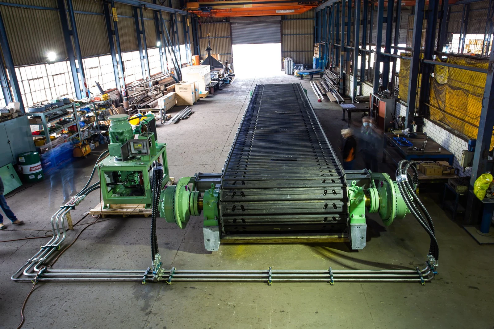
Manufacturer image of a TAKRAF underground apron feeder, 2.4 m wide and 15 m long
TAKRAF product-gallery image: an underground apron feeder 2.4 m wide × 15 m long, showing pans, chains, head end and frame.
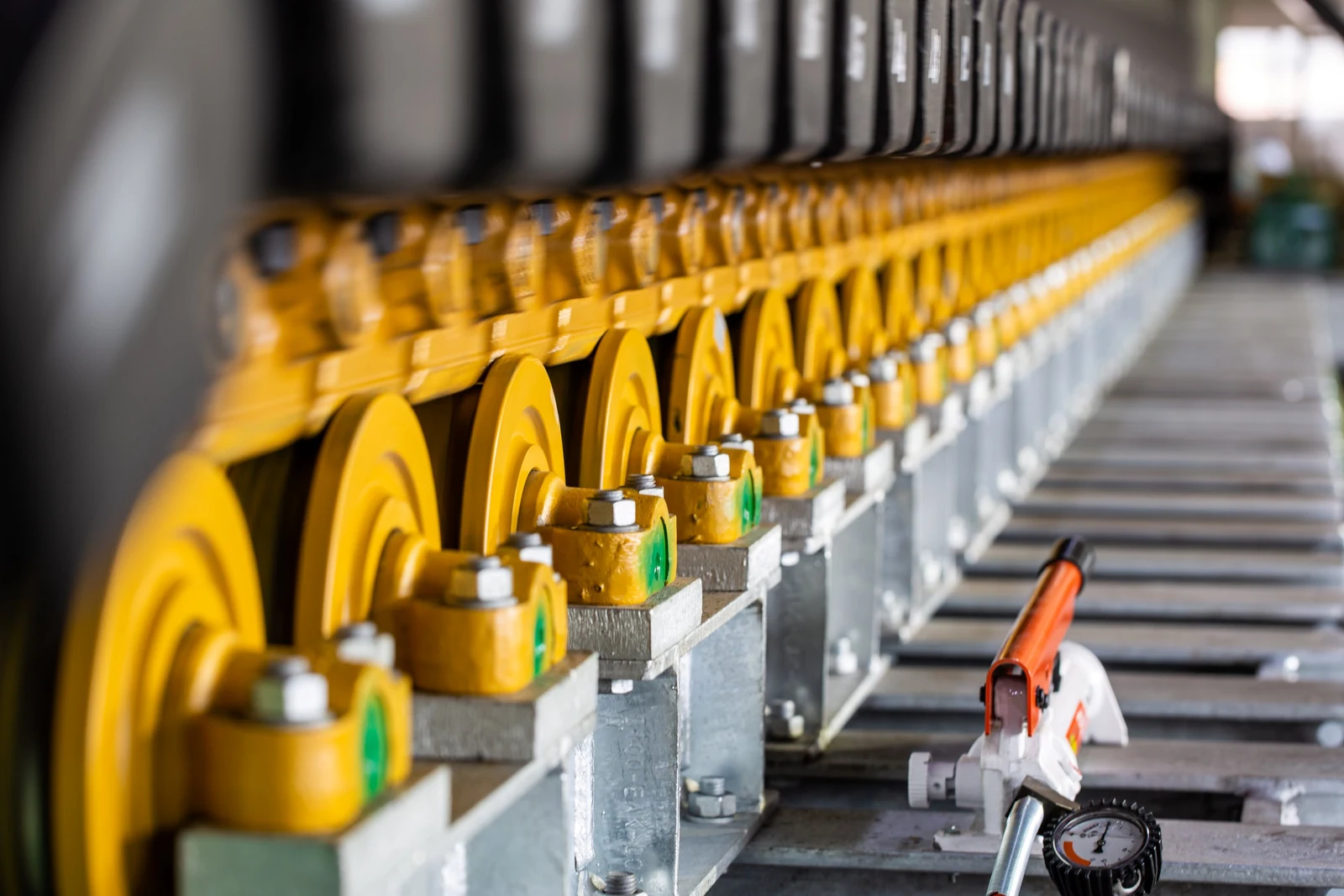
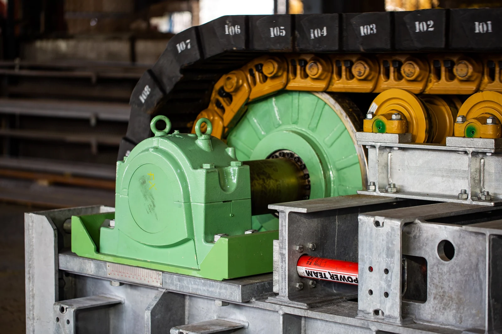
TAKRAF apron feeder upper rollers and chains, manufacturer image
TAKRAF product-gallery image showing upper rollers, chains and the pan support zone.
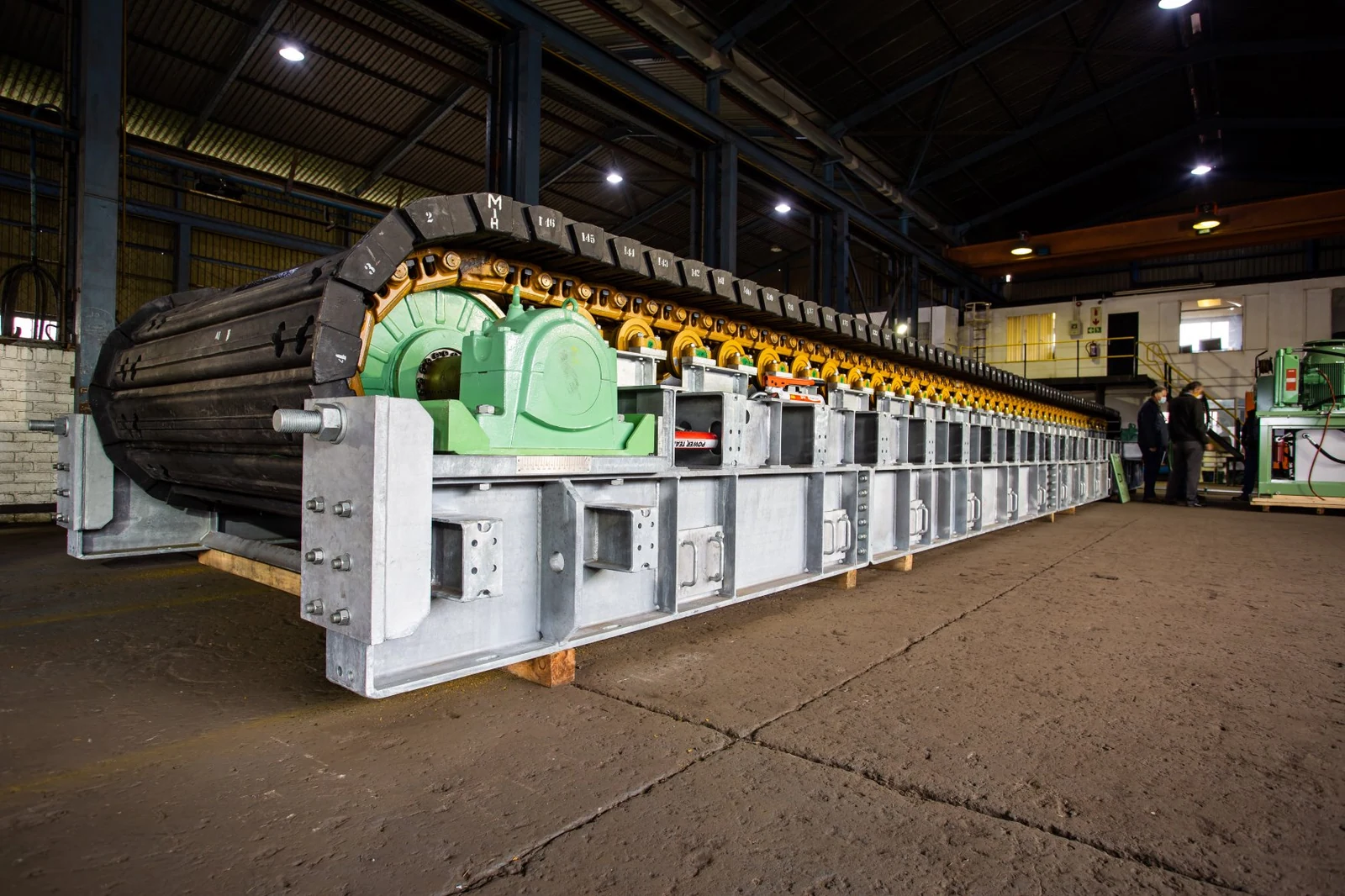
TAKRAF apron feeder tail-shaft section, manufacturer image
TAKRAF product-gallery image showing the tail shaft, traction wheels, tail bearing housings and tensioning zone.
OEM equipment guide

Identify Wear Parts and Spares from Pans, Crawler Chains and Shafts

TAKRAF heavy-duty apron feeders receive and meter large, abrasive, heavily loaded or hot materials. Overlapping pans connect to multiple heavy crawler-chain strands and run on head and tail shafts, sprockets, rollers, tensioning and drive systems. For spares, confirm inboard/outboard chains, pan design, chain pitch, width, overall length, shafts, drive, receiving zone, inclination, project/serial number, drawing revision and actual interfaces.

1,000–3,240 mmCurrent published width range
Up to 30,000 mmCurrent published length range
Horizontal to 28°Current published inclination range
D4–D9Standard dimensions in the manufacturer brochure
Models and key specifications

Current Range, D4–D9 Dimensions and Documented Project Models

The current product page publishes project-based width, length and inclination ranges. The brochure also gives head-shaft dimensions for D4, D6, D7 and D9. These help identify equipment but do not establish interchangeability of pans, chains, sprockets, bearings, drives or modified parts.

Published model / rangePublished key dimensions or capacityProject and identification notesTime status
TAKRAF apron feeder rangeWidth 1,000–3,240 mm; length up to 30,000 mm; inclination horizontal to 28°Heavy-duty project equipment; identify inboard/outboard chains, pans, chain pitch, shafts, drive and receiving-zone configurationCurrent product range
D4H 1,130 mm; C 638 mm; R 492 mm; length depends on applicationBrochure dimensions; standard widths 1,000 / 1,250 / 1,530 / 1,830 / 2,100 / 2,400 mmManufacturer brochure dimensions
D6H 1,345 mm; C 773 mm; R 572 mm; length depends on applicationBrochure dimensions; confirm pans, chains, sprockets, shafts and drive from drawingsManufacturer brochure dimensions
D7H 1,520 mm; C 900 mm; R 620 mm; length depends on applicationBrochure dimensions; confirm receiving zone, impact rails and pan design by projectManufacturer brochure dimensions
D9H 1,786 mm; C 1,010 mm; R 776 mm; length depends on applicationBrochure dimensions; D9 alone does not establish shaft, drive or chain interchangeabilityManufacturer brochure dimensions
BRF-W2-10000Published capacity 10,000 t/hApron feeder in the fully mobile crawler crushing station at Australia's Clermont coal mine; confirm project number, mobile-station interfaces, receiving arrangement and drawingsProject documented in 2009
Provide the full model, project/serial number, inboard or outboard chain arrangement, pan photographs, chain pitch, width, overall length, shaft/drive details, OEM drawing or general arrangement, used-part photographs and key interface dimensions. D4–D9 dimensions and BRF-W2-10000 project data cannot replace component drawings.
TAKRAF

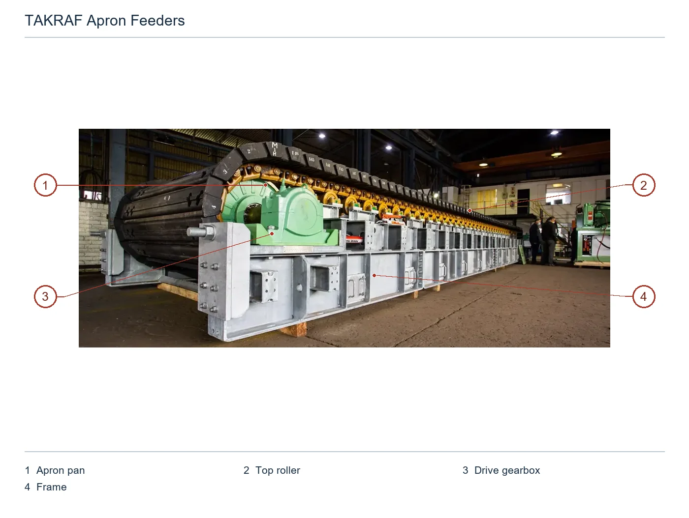
Component Location Diagram

The numbers on the diagram correspond one to one with the rows below.

TAKRAF Heavy-duty apron feeders – Component Location Diagram
No.ComponentLocationApplies to
1Apron panContinuous carrying pans along upper runTAKRAF Apron Feeder (OEM factory configuration for underground project)
2Top rollerVisible top roller beneath upper chain runTAKRAF Apron Feeder (OEM factory configuration for underground project)
3Drive gearboxGreen drive gearbox at front leftTAKRAF Apron Feeder (OEM factory configuration for underground project)
4FrameGrey supporting frame beneath feederTAKRAF Apron Feeder (OEM factory configuration for underground project)
Wear parts

Pans, Impact Rails and Receiving-Zone Protection

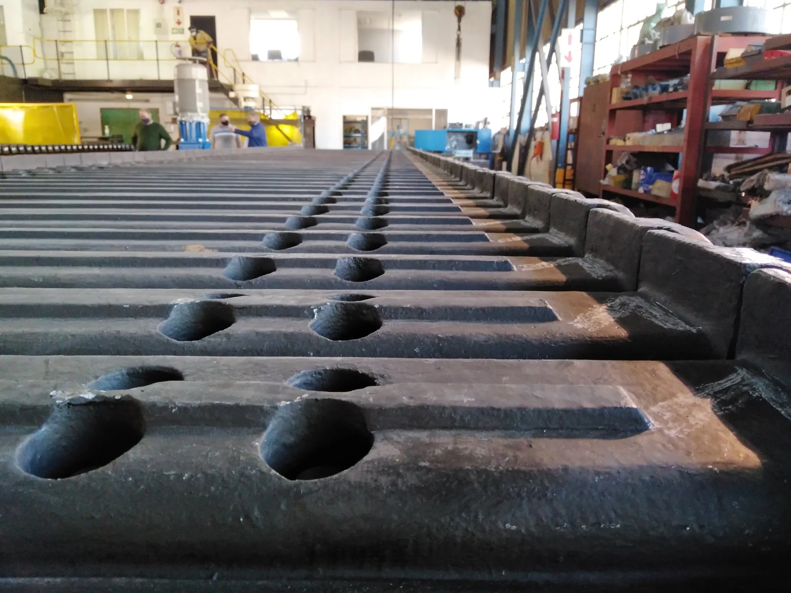
The wear system centres on carrying pans, their receiving surfaces, impact rails and hopper/skirt protection. The manufacturer describes welded or cast pans reinforced underneath and connected to two crawler chains. Confirm material, thickness, segmentation, hole spacing and fastening by processed material and drawings.

TAKRAF manufacturer image locating receiving-zone pans and impact supports
02

Receiving-Zone Impact Rails and Pan Underside Protection

Impact Rails & Pan-Deck Protection

The manufacturer describes impact rails within the frame supporting pans under exceptional impacts. Provide the drop point, lump size, drop height, impact frequency, rail design, mounting holes, support interfaces and maintenance access.

View the component guide →
TAKRAF factory-acceptance image locating hopper, skirt and frame areas
03

Hopper, Skirt and Spillage-Zone Protection

Hopper, Skirtboard & Spillage-Handling Protection

Identify liners and guards at hopper discharge, skirts, side guides and spillage-handling areas. Check material flow, moisture, buildup, fall direction, hole spacing, fastening, cleaning access and adjacent conveyor interfaces.

View the component guide →
Spare parts

Crawler Chains, Sprockets, Shafts, Rollers and Drive Spares

The manufacturer lists forged alloy-steel head and tail shafts, replaceable bolted sprocket segments, steel traction wheels, rollers, hydraulic tail tensioning and hydraulic/electromechanical drives. Confirm drive and load-bearing parts together with model, chain pitch, pans, shaft ends, housings, drive and modification records.

TAKRAF manufacturer image of the head end and crawler chains, locating the head shaft and sprockets
01

Head Shafts, Sprocket Hubs and Replaceable Segments

Head Shaft, Sprocket Hub & Replaceable Segments

The head shaft is described as forged alloy steel; sprockets comprise hubs and replaceable bolted segments. Check shaft ends and shoulders, chain pitch, tooth count, hubs, segments, fasteners, rotation and position.

View the spare-parts catalogue →
TAKRAF manufacturer image locating the tail shaft, traction wheels and tensioning system
02

Tail Shafts, Traction Wheels and Hydraulic Tensioning

Tail Shaft, Traction Wheels & Hydraulic Take-Up

The tail shaft is forged alloy steel, with steel traction wheels secured by keys or clamping elements. Single-acting hydraulic cylinders act on the tail bearing housings to tension the chains. Provide the general arrangement, tensioning stroke, cylinder interfaces and used-part details.

View the spare-parts catalogue →
TAKRAF apron feeder upper rollers and crawler chains, manufacturer image
03

Crawler Chains, Carry Rollers and Return Rollers

Crawler Chains, Carrying Rollers & Return Rollers

Crawler chains may use split or pin-type master links. Carry and return rollers are sealed, lubricated crawler-type rollers with flange guidance. Check chain pitch, links, roller diameter, flanges, bearings, seals and inboard/outboard arrangement.

View the component guide →
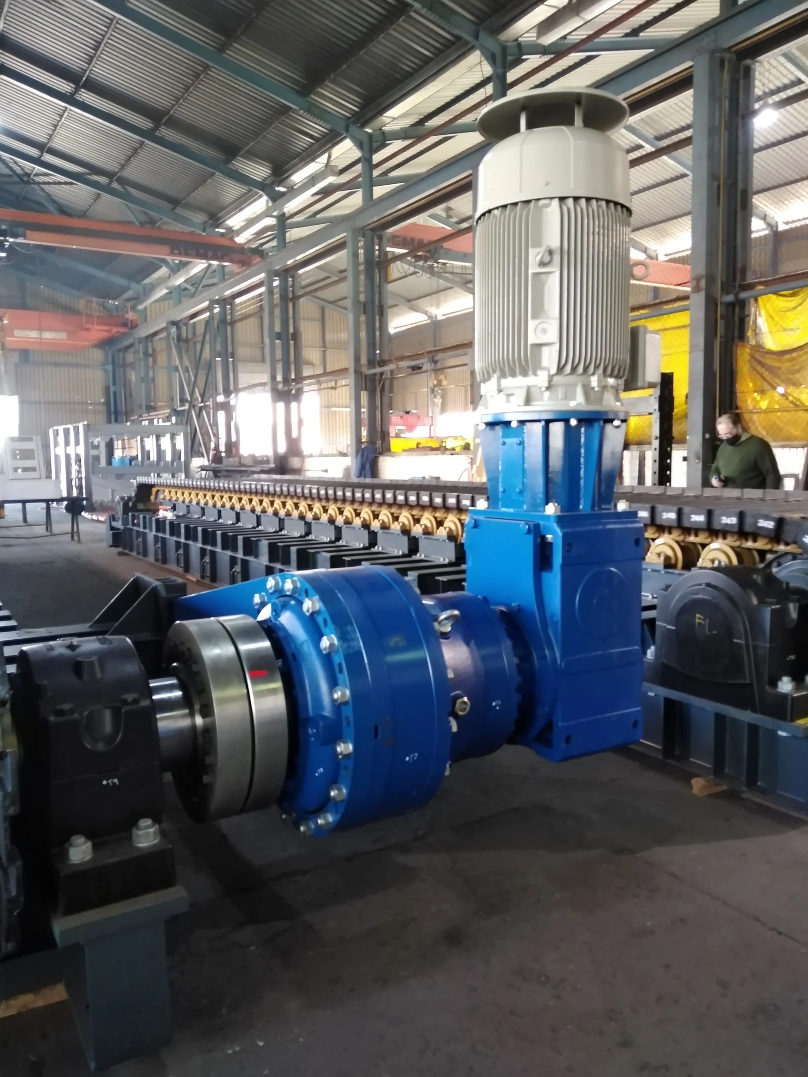
TAKRAF apron feeder electromechanical drive, manufacturer image
04

Electromechanical / Hydraulic Drives, Gearboxes and Connections

Electromechanical / Hydraulic Drive, Gearbox & Couplings

Drives may be hydraulic or electromechanical. The electromechanical option uses a planetary gearbox with an additional bevel stage and supports up to two variable-speed drives. Check motors, gearboxes, ratios, couplings, torque arms, flanges/locking assemblies, controls and rotation.

View the spare-parts catalogue →
FAQ

Frequently asked questions

What information is needed for TAKRAF apron-feeder spares?

Provide the full model, project or serial number, chain arrangement, pan photographs, chain pitch, width, overall length, shaft and drive details, OEM references or drawings, used-part photographs, key interfaces, materials and duty.

Do D4, D6, D7, D9 or equal widths establish pan, chain or sprocket interchangeability?

No. Pan pitch, chain pitch, sprocket tooth count, shafts, drives, receiving zones, modifications and drawing revisions can differ. Check installation records and physical interfaces.

Send Your TAKRAF Model, Drawing or Used-Part Details

Provide the full model, project and serial numbers, chain arrangement, pans and chain pitch, receiving zone, shafts, drive, OEM drawings, used-part photographs, materials and duty. We use these for technical advice, supplier coordination, quality control and finished-part delivery.

Equipment Brand and ModelDrawingDrawing or DimensionsCurrent MaterialPhotographs of Failed PartsTarget Service LifeOperating Conditions
Request a Quote

Or contact us directly: +86 156 3797 3199
zzx@anranst.com

Manufacturing Services in China

From Technical Assessment to Finished-Part Delivery

ANRANST provides customers worldwide with engineering assessment, production at certified foundries to the customer technical requirements, quality control and finished-part delivery for custom wear parts and industrial spares, with scope to support other custom industrial parts.

01

Drawing and Engineering Review

We review mating surfaces and interface dimensions and assess material, heat treatment and manufacturing feasibility.

02

Material and Heat-Treatment Specification

Material grades and heat-treatment processes are specified order by order, stated in the technical agreement and tracked through production.

03

Quality Control

Drawing confirmation, material and process control, production tracking, inspection and acceptance coordination.

04

Finished-Part Delivery

We coordinate manufacturing, quality confirmation, packaging and delivery of complete finished parts in a workable, closed-loop supply process.

Provide the existing model, drawings, drawing, materials or operating conditions so we can identify the appropriate technical review and supply route.

Submit an Enquiry