
Metso MX Series Multi-Action Cone Crushers

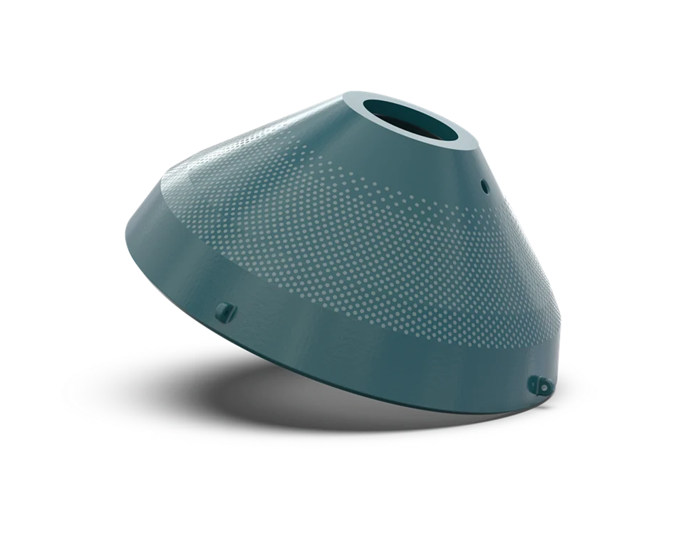
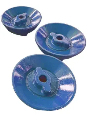
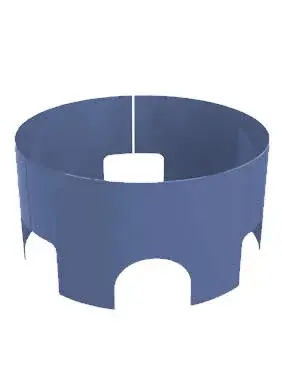
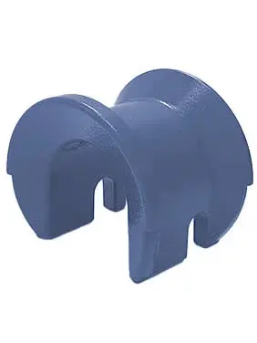
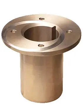
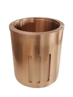
Identification and supply of crushing-chamber liners, frame guards, bushes, gears, seals and the MX4 mantle lifting tool for installed MX3 and MX4 crushers.

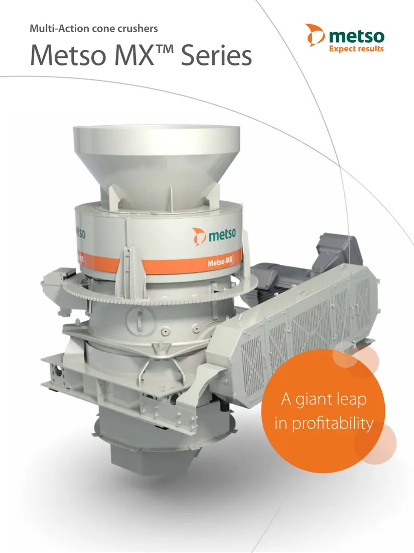
Metso MX Series Multi-Action Cone Crusher
Metso MX Series complete machine, used to identify the feed system, rotating bowl assembly, main frame and drive arrangement.
Installed Metso MX Series cone crusher
Installed MX Series machine, used to identify the feed system, machine layout and maintenance clearances.
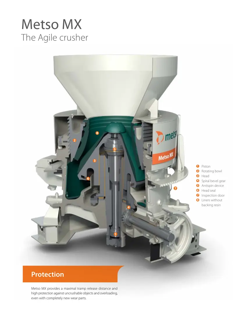
Metso MX Series Multi-Action cone crusher cutaway
MX Series cutaway showing the piston, rotating bowl assembly, head, spiral bevel gear, anti-spin device, head seal and liner zones.
OEM Equipment Series

Identify MX3 or MX4 First, Then Confirm Chamber, Drawing and Installed Version

The MX Series uses both a piston and rotating bowl assembly to adjust the setting and compensate for wear. Liners must be identified as a matched set for the machine model and chamber. Bushes, gears, seals and hydraulic parts also require the serial number, interfaces and fit dimensions.

2OEM Published Specifications (2019) — Model
1050 / 1175 mmHead Diameter
230 / 257 mmMaximum Feed Opening
220 / 315 kWMaximum Power
OEM Published Specifications (2019)

Metso MX3 and MX4 Model Range

This table retains the head diameter, feed opening, power, overall dimensions, weight and maximum capacity published in the 2019 OEM brochure. It is not presented as a current global availability list.

ModelHead DiameterMaximum Feed OpeningMaximum PowerOverall Dimensions (L×W×H)Machine WeightMaximum Capacity
MX31050 mm230 mm220 kW3400 × 2490 × 2845 mm16,600 kg300–420 t/h
MX41175 mm257 mm315 kW3700 × 2840 × 2930 mm21,200 kg400–600 t/h
Capacity varies with feed gradation, chamber, bulk density, moisture and crushability. Manufacturing spare parts still requires the serial number, chamber type, drawing revision and measured dimensions.
Metso

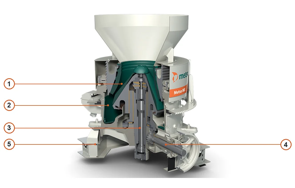
Component Location Diagram

The numbers on the diagram correspond one to one with the rows below.

Metso MX Series Multi-Action Cone Crushers – Component Location Diagram
No.ComponentLocationApplies to
1MantleGreen mantle on moving cone
2Bowl linerStationary bowl liner outside mantle
3Main shaftCentral vertical main shaft
4CountershaftHorizontal countershaft on right
5Main frameLower main frame
Wear Parts

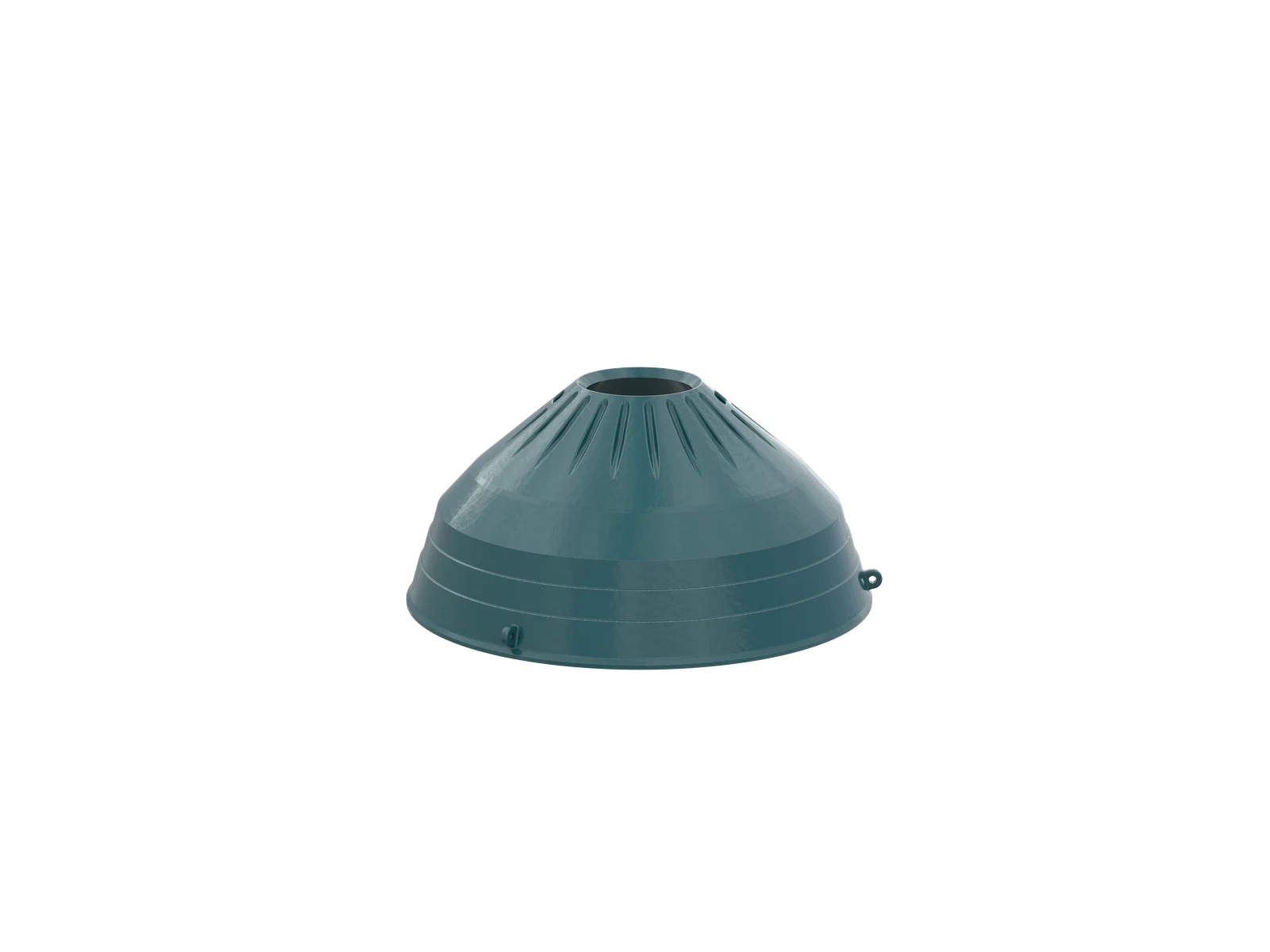
Crushing-Chamber Liners and Frame Guards

Each installation position lists its loads, wear and candidate materials separately. Match mantles and bowl liners as a set for the MX model and chamber.

Spare Parts

Drive, Bearing, Sealing and Adjustment Systems

Confirm standard spare parts by construction, material, tooth geometry, fits, lubrication and installed version; the MX Series name alone is insufficient.

FAQ

Frequently asked questions

What information is needed to quote MX3 or MX4 liners?

Provide the complete model, serial number, crushing-chamber type, drawing or current model details, closed-side setting, used-part photographs, material, feed and wear conditions.

Are MX3 and MX4 liners and spare parts interchangeable?

They are not interchangeable by series name. Check each machine model, chamber type, drawing revision, interfaces, fits and used-part dimensions separately.

How should material be selected for MX Series crushing-chamber liners?

High-manganese steel is the usual candidate. Composite wear options may be assessed for highly abrasive and impact duties; final selection depends on rock type, feed, closed-side setting, wear pattern and target service life.

Submit the MX3 or MX4 model, liner number or spare-part drawing

Provide the complete model, serial number, nameplate, installation position, photographs of the current part, drawings, material and operating conditions. We use these to identify the part, assess materials, organize production at certified foundries, coordinate quality control and arrange finished-part delivery.

Equipment Brand and ModelDrawingDrawing or DimensionsCurrent MaterialPhotographs of Failed PartsTarget Service LifeOperating Conditions
Request a Quote

Or contact us directly: +86 156 3797 3199
zzx@anranst.com

Manufacturing Services in China

From Technical Assessment to Finished-Part Delivery

ANRANST provides customers worldwide with engineering assessment, production at certified foundries to the customer technical requirements, quality control and finished-part delivery for custom wear parts and industrial spares, with scope to support other custom industrial parts.

01

Drawing and Engineering Review

We review mating surfaces and interface dimensions and assess material, heat treatment and manufacturing feasibility.

02

Material and Heat-Treatment Specification

Material grades and heat-treatment processes are specified order by order, stated in the technical agreement and tracked through production.

03

Quality Control

Drawing confirmation, material and process control, production tracking, inspection and acceptance coordination.

04

Finished-Part Delivery

We coordinate manufacturing, quality confirmation, packaging and delivery of complete finished parts in a workable, closed-loop supply process.

Provide the equipment brand, complete model and serial number, part name, part number or drawing number, drawing revision, quantity, material requirements and duty. If identifiers are unavailable, send photographs and key dimensions.

Submit an Enquiry