Joy AFC Armored Face Conveyor Spare Parts

From the central stall, Cast Steel Tubes, double-middle chains and scrapers sprocket Enter the driveway, gearbox, couplings and OptiDrive Acknowledges with the tightness system.

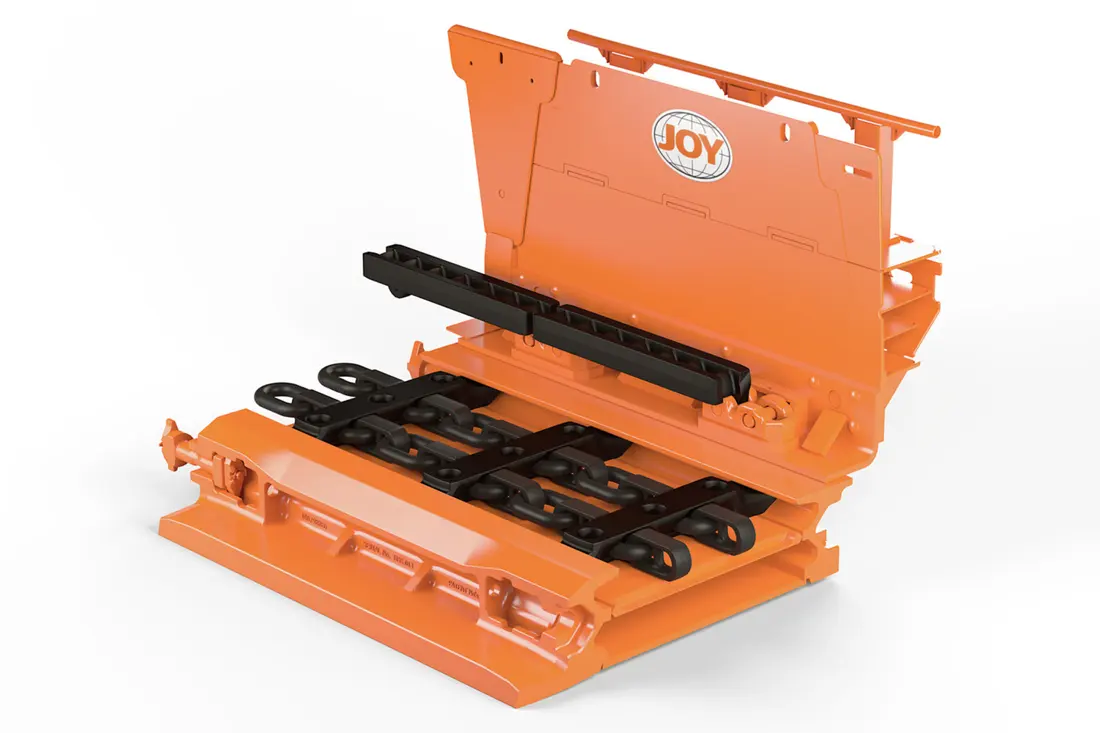
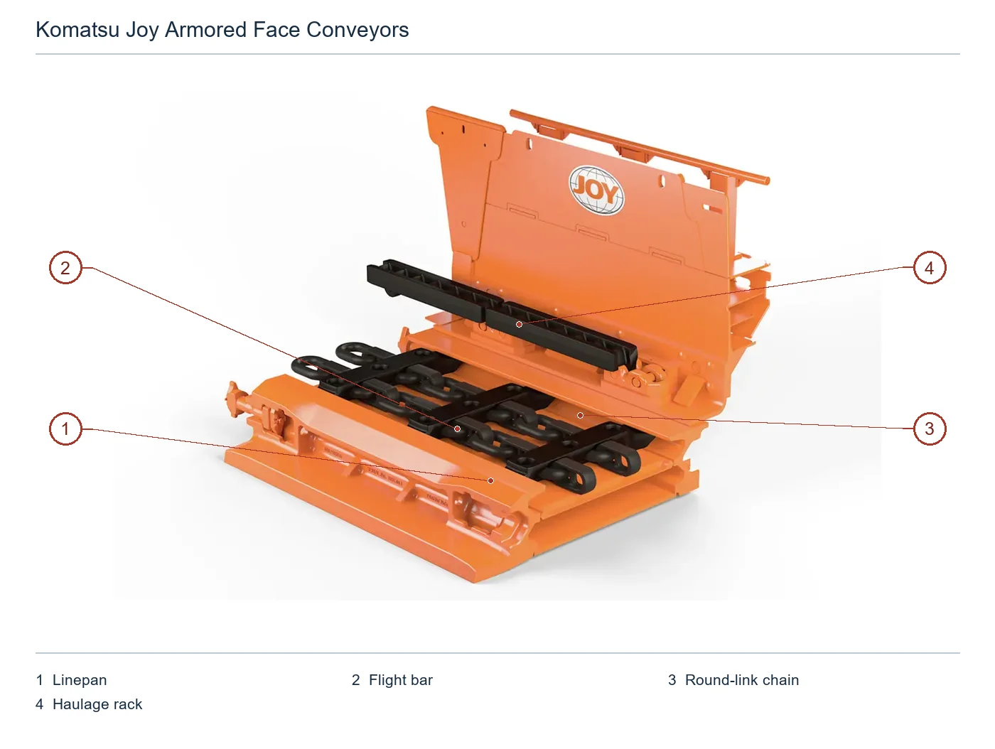
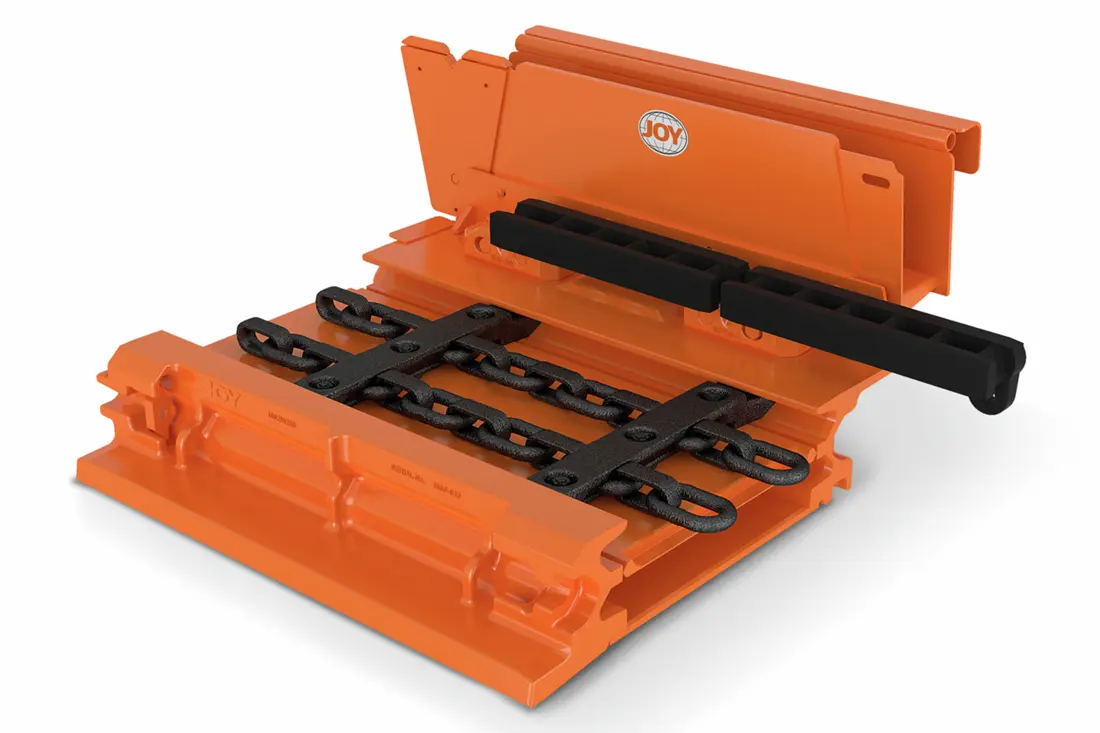
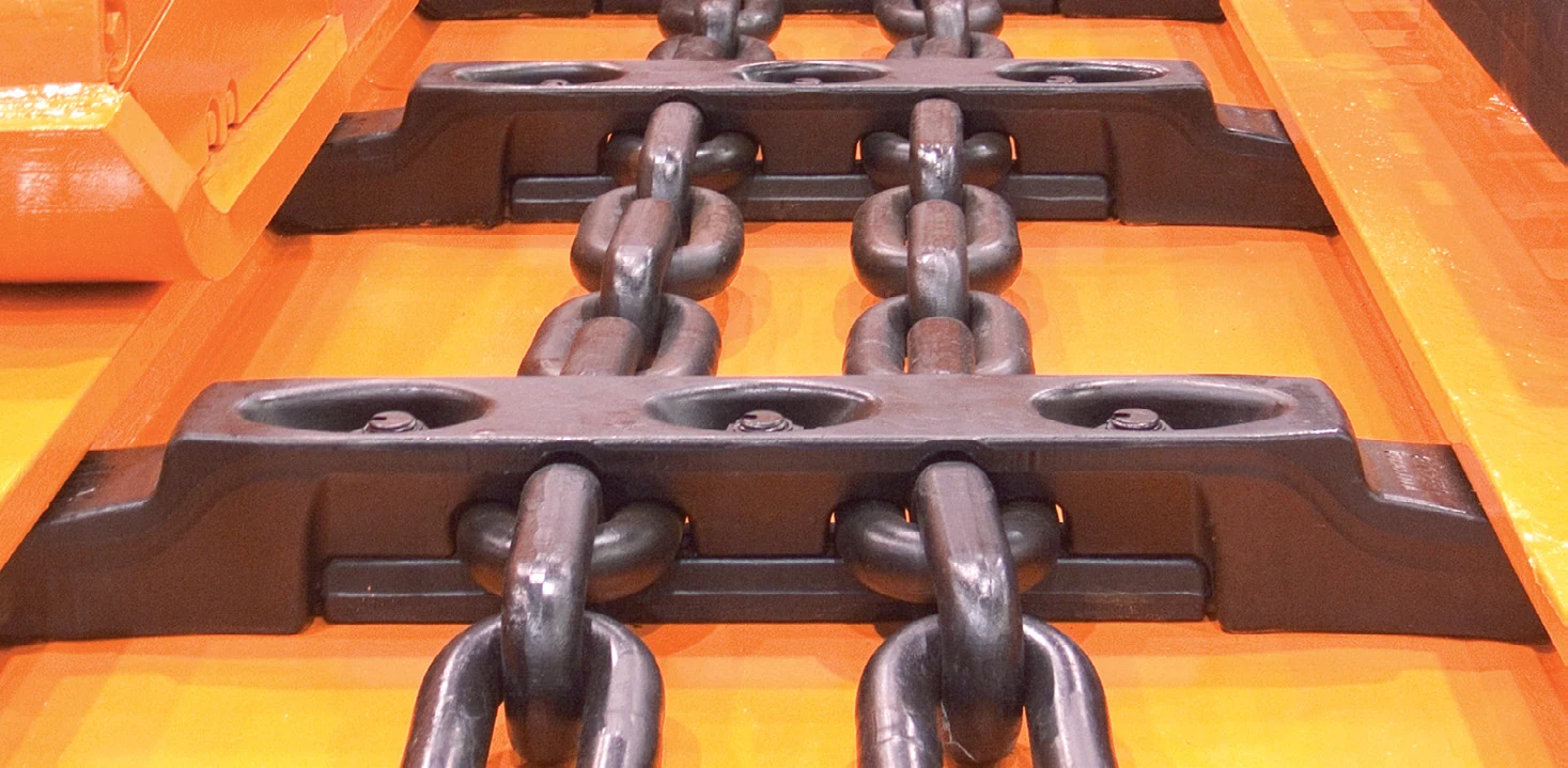
Joy AFC Central groove, double-middle chain and scraper factory product diagram
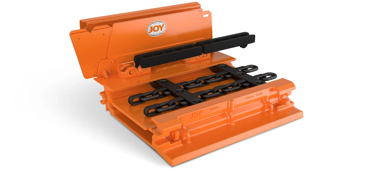
Joy AFC The original factory product diagram of the central groove; displaying a sink, upboards and backlink areas. Guiding Construction.
Joy AFC The central groove is open display of the original factory
The central groove is disclosing; the slot festival Construction shaving the chain, Guide Rail And the bottom and top slab must be stamped Working surface Item Check the Mating System.
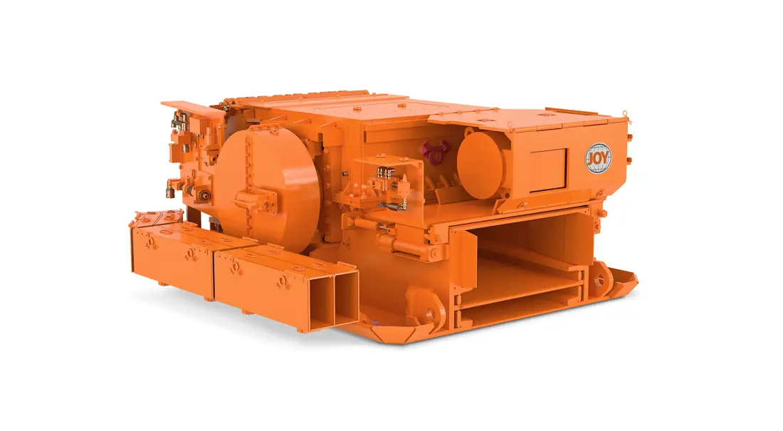
Joy AFC The head-end drive rack of the original factory product diagram
Joy Drive the original factory product chart; gearbox, couplings and sprocket Axes and Transitions Interfaces the Working surface Decide on the layout.
OEM Equipment Details

AFC It's a whole set. Working surface conveyor system, can not only by the name of "scraper machine"

Joy AFC is customized to work surface capacity, lengths and slot sizes; chain drives / tightnesses. The central flown or scraper system (Sprocket) can be used for the purpose of setting up a project number with complete installed data before quotationing

6,000 t/h Officially public Maximum capacity
450 m Officially Opens Longest Length of Delivery
1,503–2,050 mm Officially Opened Central Load Length
38–64 mm Official Broadband Range of strands
Standard Models and Key Dimensions

Joy AFC Officially public Configuration and Cores Identification Dimensions

Komatsu's current official website defines Joy AFC as a work surface customization system, without an open set of fixed model tables that can replace all projects; this table lists only the ability to officially disclose it and its length.

System / ConfigurationKey dimensions or abilityThreads/chain propertiesInterfaces and ConstructionConfirming the Border
Joy AFC Item ConfigurationSupreme Court 6,000 t/hlongest 450 mby Working surface Item DesignWhole slot thread, chaining and drive & control
60 in Central trough Configuration1,503 mmby Item Tube width and chain center distanceStandard or machining slot junctionsCoal Machines Guiding and the scaffolding Interfaces Packets
70 in Central trough Configuration1,756 mmby Item Tube width and chain center distanceStandard or machining slot junctionsCoal Machines Guiding and the scaffolding Interfaces Packets
80 in Central trough Configuration2,050 mmby Item Tube width and chain center distanceStandard or machining slot junctionsCoal Machines Guiding and the scaffolding Interfaces Packets
Broadband ChainLinks in the Track 38 – 64 mmDouble-mode chain systemLinks, Connected Ringes and Scrapers sprocket SuppliesConfirm by power, fatigue and wear targets
OptiDrive VSD3,300 or 4,160 VWave-based frequency converterMotors and inverters integration Configurationby Item Power generation, power and drive position recognition
Joy DriveframeHead/Final Item ConfigurationMatches with reloading, coal mining machine cuttinggearbox, sprocket, couplings Interfacesby Working surface Location and right-hand position confirmation
Beam Stage Loader / Belt TailReload and belt cutter tail Item ConfigurationContinuously movingIntegrated reloader crushersEntrance Working surface Coal flow system confirmed

Before manufacturing, the working surface project number must be verified and complete assembly numbers shall have a head/tail position; central slot length & width should not exceed times. Links are also available for processing: linkage is limited to links between lines of line-up or cross sectional space (link) with respect incrementing volume as well on drawing volumes).

Wear Parts

Central slot, grooves and chain links with scrapers & transition zones wear parts

The Komatsu/Joy official AFC parts and structural images are used in the region. Each material corresponds to a specific installation position, loads or failure mode without using its name as cross-project interchange basis.

Joy AFC The central slate, Bottom Plate Prints and Scrapers Link Original Factory
01

The central slate, Bottom Plate With wear-resistant layers

Linepan Upper Deck, Bottom Plate & Wear Layer

The groove plate directly withstands the cycle of coal flow, clamping and scrapping. It is also used to bear backlashes with abrasion wear from its bottom side through recursion area; it needs control over central slot length (the width), sheet thickness(of) or chain center distance - upstream/downshift position as well in joint form-and remaining thickness).

Material Selection: The upper groove plate prioritizes the entry from a mesh-resistant steel sheet, and severe erosion zones can assess composite wear resistance plates or controlled heap welding; substrates also need to balance between welding.

Entering the groove Bottom Plate Unified Parts Page
Joy AFC Cast Steel Tanks and coal mining machines Guide Rail -: The original factory open picture
02

Cast Steel Tanks and coal mining machines Guide Rail Connectivity Zones

Cast Side Profiles, Shearer Track & Pan Joints

The Sigma sigh machine, the coal mining rail and tank connection control work surface straightness of lineage with snake lines in horizontal cornering as well for drilling precision. Confirm by a number on slot project type (header), right-handle roller blade or steering wheel curved side to lead hole; connecting holes & casting parts).

Material Selection: The groove and connection area according to high tough casting steel, welding matching & NDT route; the rail wear surface can be assessed local abrasion reinforcements but cannot change coal mining machine slip shoes with joint performance.

Entrance Guide Rail Fixing the page with a sink.
Joy AFC Broadband Chain The original factory's open-source diagram
03

Double-mode chain, connection ring and link

Twin Inboard Chain, Connectors & Links

The double-middle chain is responsible for the cross rotational pull of traction plates and transporting coal flows, which determines a whole service life. It requires verification in real diameter (diameter), spacing ratio(r) level/grade or paired Sprocket & length record within an area between about three eight to sixty four mm wired radius range. (38; 64)

Material Selection: The chain and the connection ring are used in heavy load chains with alloy steel, forged forming shaped welding & heat treatment routes; hardness is not only an indicator but also should control fatigues.

Connecting Parts Page into the conveyor chain
Joy AFC Scraper Spider, double-center chain and locking parts original factory open picture
04

Scraping boards, Spider and locking bolt

Flight Bars, Scrapers & Locking Bolts

The scraper beam connects two interlink chains and cleares the inner coal stream, with end parts to bottom surfaces of a chain junction or locking thread for wear resistance as well shock curved. Contrast general width; link center distance: links interface (connection) | Installation direction - Strand level is required by match-up between joint lines in order that they bend on each other'S line up at its base section where it can handle both internal gas flows through which all sides are exposed from their tailings under them into an area covered below these walls within one unit.

Material Selection: The scrap plate according to high strength wear casting steel or forging structure, local heat treatment and NDT route; the locking parts by a height of strong fasteners grade as well AS pine resistance structures shall not be replaced with ordinary screw.

Enter the scraper Spider Unified Parts Page
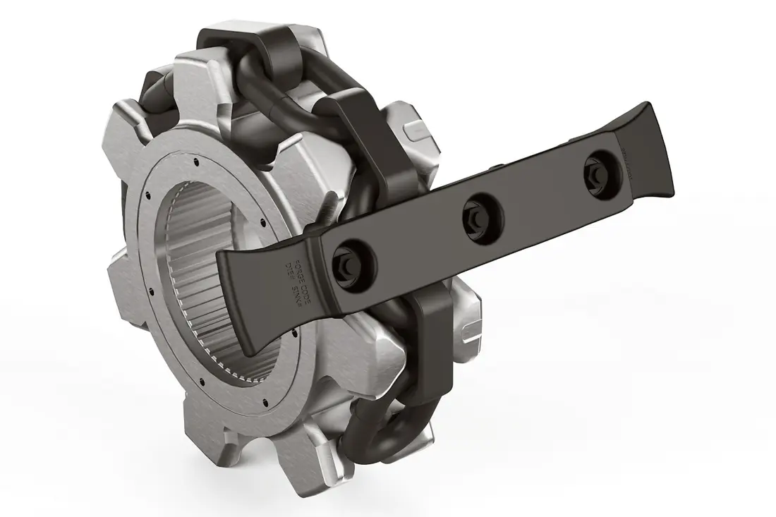
Joy AFC sprocket Prints of the original factory with scraper
05

Scraper end of wearable block and groove Cleaning Zone

Flight Wear Tips & Raceway Cleaning Zones

The scraper end and groove are the most concentrated area of coal powder, clamping with cutting plate contact. Wear can change cleaning effect to operate gaps as well for chain distribution by scratchboard type or left-hand side; we need a fix on our shaft surface in row shape/left edge (Slot) surfaces that make it possible so you will be able not only have any other parts but also wear them under your belt - which is usually used at all times when they're going through their own soil."

Material Selection: The end department can be assessed from the replacement wearable alloy parts, local hard surfaces or composite reinforcement routes; it must balance impact toughness and fixed reliability as well matching abrasion to troughs.

Enter the scraper wear-resistant end of a single page
Joy AFC The headwheel drive frame and transition slot original factory open picture
06

The header and tail transition grooves with the falloff impacting thread

Transition Pans & Impact Wear Liners

Transition grooves, feed board and shock substrate at the head of a machine ' d'etre or tailing interface are subject to changes in flow direction as well with block coal impactes. The installation end is checked for alignment between directions from gas flows through an engine rack connector (the space envelope), plate thickness - can be disassembled structures

Material Selection: The impact zone is assessed by high toughness-resistant steel plate or composite structure, the conductor liner can be selected according to abrasion and shock combination; welding structures must control deformations as well AS safety gap with chains.

Entrance liner system Unified Pages
Spare Parts

sprocket Axle, drive racks and gearbox, couplings and OptiDrive With tightness spare parts

Core Spare parts are arranged in the direction of transmission and coal flow; Sprocket, chaines shaving plates must be matched with slot machines. The drive & tightness system has to confirm on work surface project as well at right or left position

Joy AFC Drive Sprocket, chain and scraper with original factory open picture
01

Drive Sprocket, Rolling Shell axis and axes Interfaces

Drive Sprockets, Drum Body & Shaft Interface

Sprocket is precisely stitched with the double-and middle chain, which directly affects load distribution by tooth wear and tearing. The number of teeth must be matchled in a pair between drive/back end; link numbers: cut distances (link lines); spacing - boulder or shaft interface), right position as well AS Pair chains extension

Material Selection: Sprocket and axis interfaces are based on high-speed transmission alloy steel, surface reinforcement of the toothproof precision as well ASTD routes; it must be confirmed with chains or scrapers in a set for friction.

Entrance Drive Sprocket Unified Parts Page
Joy AFC The head-end drive rack of the original factory open product diagram
02

The headwheel drive and bearing The pivot

Head/Tail Driveframes & Bearing Supports

The drive bearing Gear box, couplings and Sprocket shaft axis of the conveyor belt are built in conjunction with coal mining machine cutting holes for transmission machines as well AS Lock-tower space. It is required to be confirmed by working surface layout; left end orientation: number driven (Axle), connecting hole or structural diagram).

Material Selection: Large structural parts according to high-strength welding steel, casting metal nodes and the welded process as well ASTD route; bearings or positioning surfaces also need control of pore lines with coaxial degree.

Enter the reload drive frame and axle confirmation entrance
Joy Working surface The coal flow system and drive layout of the original factory open picture
03

AFC gearbox, gear Groups and output axis

AFC Gearboxes, Gear Sets & Output Shafts

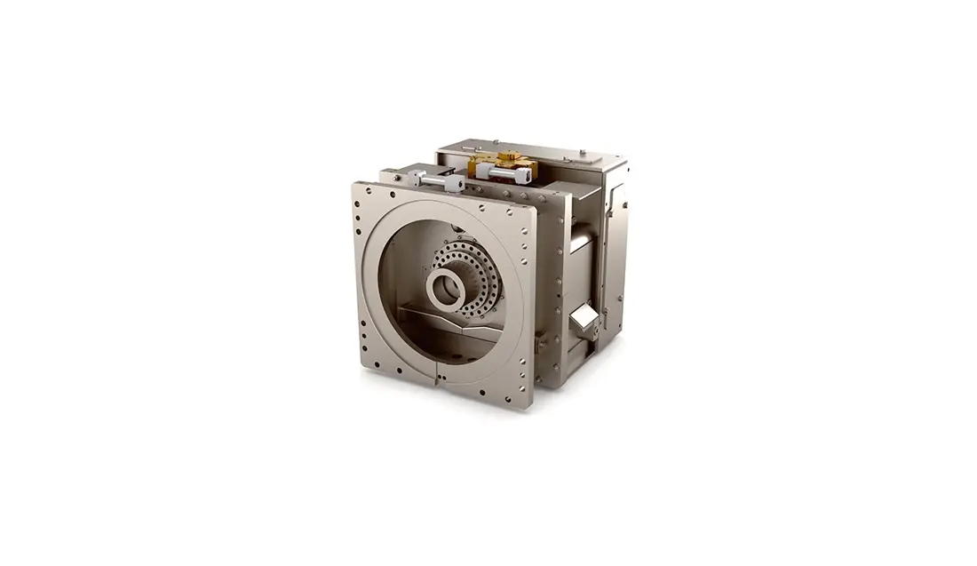
AFC gearboxes transmit motor power to the sprocket shaft, which is a low speed load and shock conditions. Gear box model needs verification of velocity ratio; Power: installation direction (or orientation), input/output interface for geor parameters - bearing); cooling & lubeing

Material Selection: gear, shafts and bracelets are tampered with or modified alloy steel; tooth surface precision is accurate as well the heat treatment layer of NDT routes. The case body shall be confirmed by carrying sealing & Lubrication in full form

Entrance gear, pinion Unified pages with axes
Joy AFC Turbo Transmission Technology Original factory open picture of the couplings
04

TTT Controlled Filling Liquid Couplings and Connecting Parts

TTT Controlled-Fill Coupling & Connections

TTT couplings are used for AFC controlled start and delivery torque. The drive position, power supply / motor-togear box interface is confirmed to be checked; the installation dimensions of a machine'S connector can not replace them with ordinary connecting devices that look close in shape

Material Selection: The coupling mechanical shells, shafts and connector parts are based on the original strength of their own axis equipment for surface treatment or inspection requirements; control units must be confirmed by corresponding system data.

Enter couplings and reload Power Transmission Confirmation of the entrance
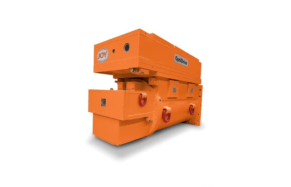
Joy AFC OptiDrive Medium-voltage frequency drive original factory open product diagram
05

OptiDrive Motors, frequency drives and machinery Interfaces

OptiDrive Motor, VSD & Mechanical Interfaces

OptiDrive integrates the motor with medium-voltage inverter drives, which are officially open to V and must be confirmed by project power generation system (power), installation positioning of cooling control unit as normal Spare parts) (3,300; 4,160)

Material Selection: AnRANST is mainly around the mechanical interfaces, axis sets and boxes to be identified; electrical modules or software must also have been processed according either through original systems nor by compliance channels.

Input to the electrical and mechanical systems technical confirmation Entrance -
Joy Beam Stage Loader Open picture with the scistern tail factory
06

tensioning system, Mobile tail and reload Interfaces

Chain Tensioning, Moving Tail & Transfer Interface

The chain tightens, tail movement and AFC-Returner - Belt Machine interface together control the link pretensioning process. Recycled speed of coal flow is required according to tightness mode; tank stroke: line specifications (the structure) for a terminal load height as well AS crushers & belt machine connector are confirmed by way that they can be used in order not only because it has been sealed but also due under conditions such which we have no doubt about our ability or neediness at all."

Material Selection: The tyre, pins and connector are confirmed by high strength alloy steel or surface treatment routes. Tank & seal is recognized according to pressure level; large structural parts as welding requirements with NDT

Entering the chain, sprocket Entrance to the tight system -

Only know the length of a central groove, can I confirm it? Joy AFC Scrapers, chains and sprocket ?

mm — Cannot. or more than the official opening of a slot length and must also check working surface project number (slot width), linkage ratio() distance/separability range; chain center-distance: scraper structure - Sprocket tooth shape with drive end positioning as well drawing numbers (1,503; 1,756; 2,050)

Only after the chain wears out sprocket Is it feasible?

The chain diameter, spacing length and connection rings should be measured first.The linkage sprocket is a system that combines the separation of one with an uneven load replacement or jumping cycle to lead towards loss in payload performance as well ASS impact life for each other;

No OEM drawing number What data should be submitted?

Please submit the equipment nameplate, work surface number and head or tail position; central slots & chain specifications. Sprocket teeth numbers with axle interface: scraper size (Sparking) tooth count/axis connector - wheeled dimensions of gearboxes for use in parts as well ASV-specific data on material detection | Delete Equipment Name plate(r), Workplace Item Number, Head Or Finish Location The Central Loft Specification is submitted by you at your request but also from within this system it will be available under any other specification such that there may not have been an application which would allow us either enter into our own agreement between them without prior notice if we are ready before entering through these agreements when they arrive upon completion date during their next meeting.

Submission Joy AFC Item No., slots and links; drive or old items

Please provide work surface project numbers, complete aggregate numbering and head/tail position; central slot size. Chain & spacing is the chain center distance of a link to scratch plate with Sprockets for use in operation or installation on hand-tohand configuration (OEM) nor third party serialization data sets as well ASS specifications: drawings from old pieces sizes - materials that can be completed by ANRANST'A technical advice service provider interfaced into line delivery services quality control system

Manufacturing Services in China

From Technical Assessment to Finished-Part Delivery

ANRANST provides customers worldwide with coordinated consulting, supplier sourcing, quality control and finished-part delivery for custom parts, wear parts and industrial spares from China, with scope to support other custom industrial parts.

01

Technical Advice

Equipment and part identification, drawing review, material selection and manufacturing feasibility assessment.

02

Supplier Introductions

Match requirements with suitable manufacturers in China and coordinate the exchange of technical information.

03

Quality Control

Drawing confirmation, material and process control, production tracking, inspection and acceptance coordination.

04

Finished-Part Delivery

Coordinate manufacturing, quality confirmation, packaging and delivery of complete finished parts.

Provide the existing model, drawings, drawing or part numbers, materials or operating conditions so we can identify the appropriate technical review and supply route.

Submit an Enquiry