Dipper Teeth and Adapters
Dipper Teeth & Adapters
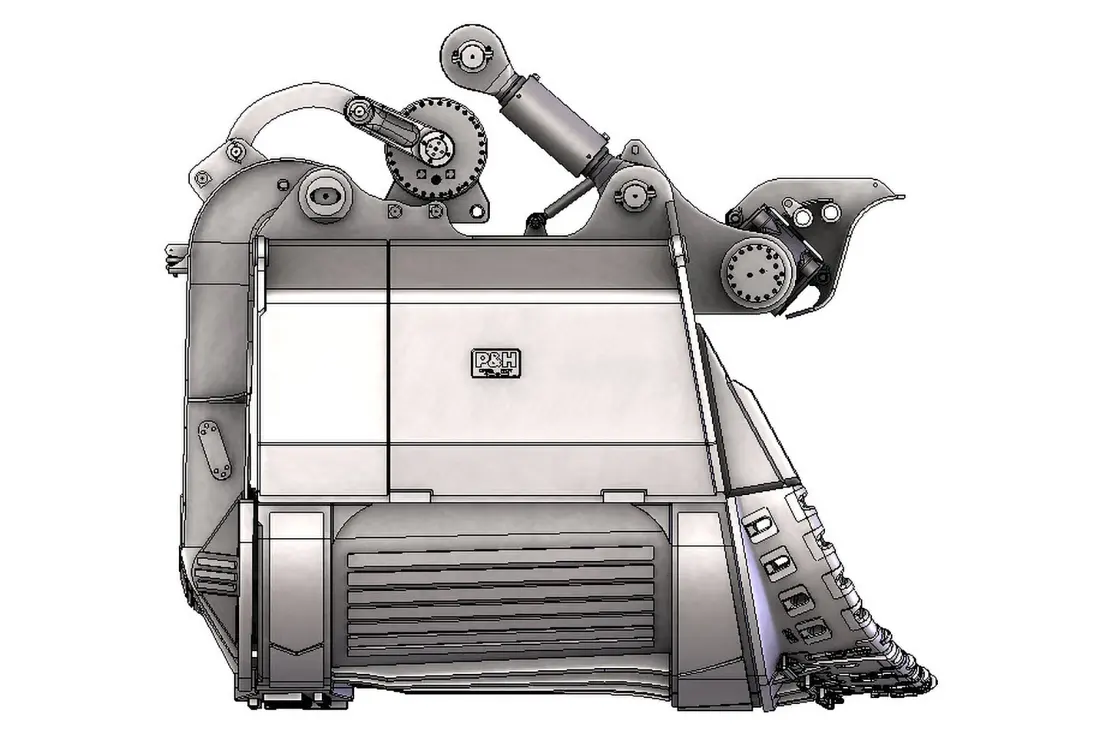
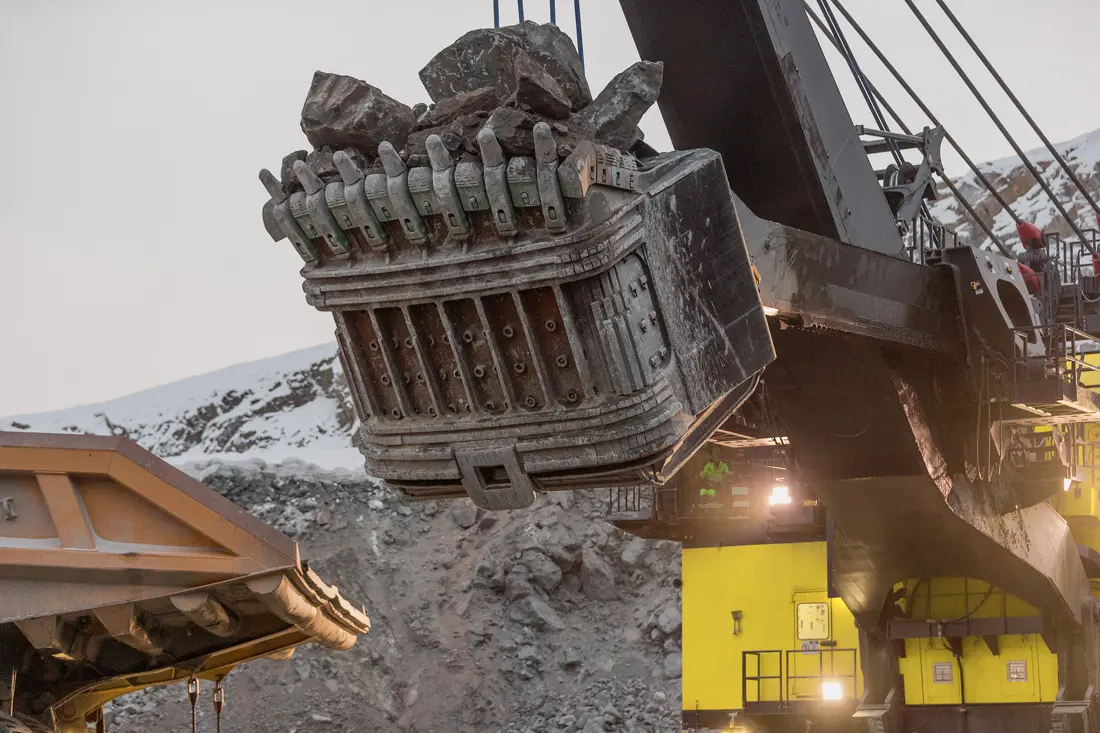
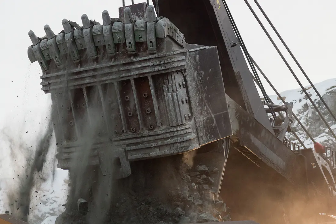
At the dipper front, they take impact, compression and abrasion on penetration. Check shovel model, dipper size, tooth system, orientation, retention and used-part wear pattern.
View Dipper Teeth →Start with 1900XPC, 2300XPC, 2800XPC, 4100C, 4100XPC and 4800XPC to identify dipper wear parts, crawler undercarriages and hoist, crowd, swing and propel drives.


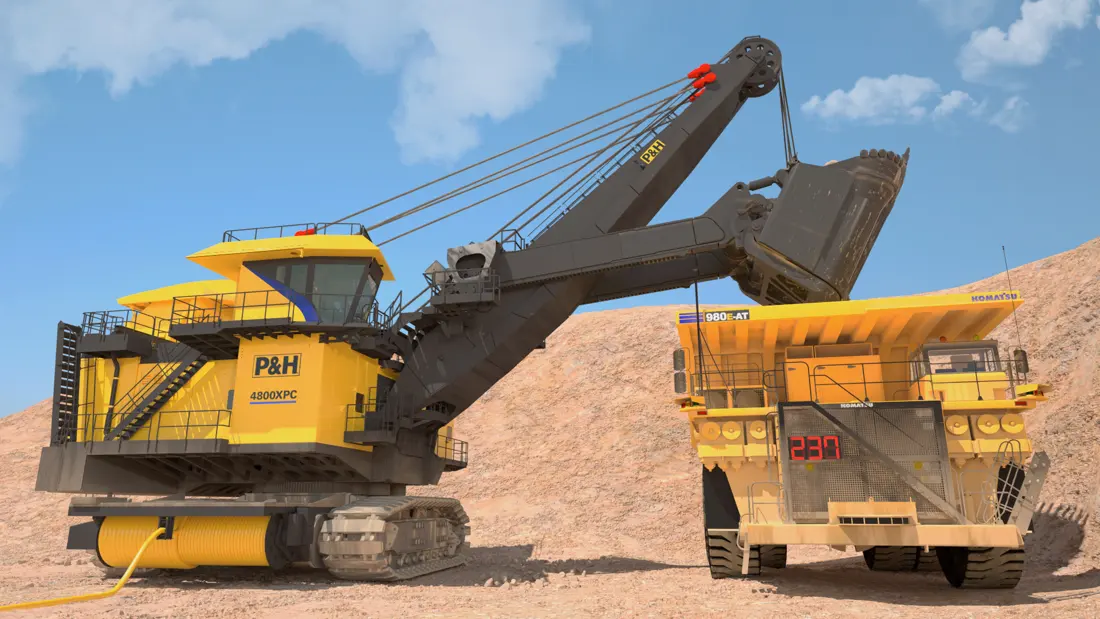
P&H shovels use motors, gear reduction, drums and ropes for hoist, crowd, swing and propel. Gears, shafts, bushings, track shoes and dipper parts vary by model and installed version. Before manufacture, check nameplate, full model, assembly position, drawings or used parts, and key dimensions.
Models and specifications come from Komatsu's current official model pages. They support initial identification and spare scoping, without replacing nameplate, serial number and configuration list.
| Standard Model | Rated Payload | Dipper Capacity | Published Reference Production Capacity |
|---|---|---|---|
| P&H 1900XPC | 18 t | 11 m³ | 1,348–1,797 t/h |
| P&H 2300XPC AC | 45 t | 18–25 m³ | 3,365–4,488 t/h |
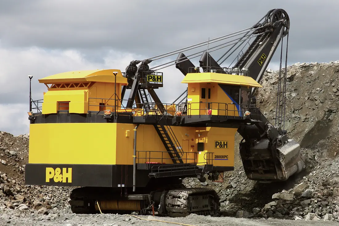
| P&H 2800XPC | 59 t | 26.8–33.6 m³ | 5,702–7,603 t/h |
| P&H 4100C AC | 72.5–82 t | 41–49 m³ | 7,184–9,579 t/h |
| P&H 4100XPC AC-90 | 73–82 t | 42–49 m³ | 7,183–9,578 t/h |
| P&H 4100C BOSS | 90.7 t | 49 m³ | 6,830–8,707 t/h |
| P&H 4100XPC | 99.8–108.9 t | 52.8–61.2 m³ | 7,834–10,444 t/h |
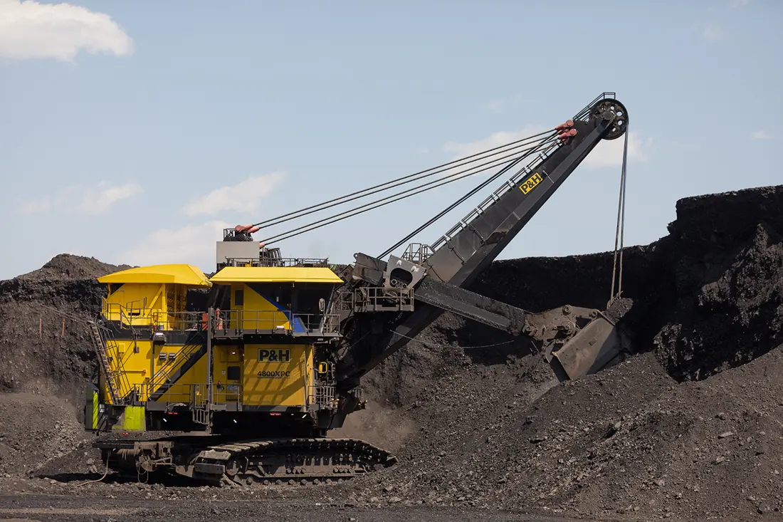
| P&H 4800XPC | 123 t | 65.7–70.3 m³ | 8,810–11,748 t/h |
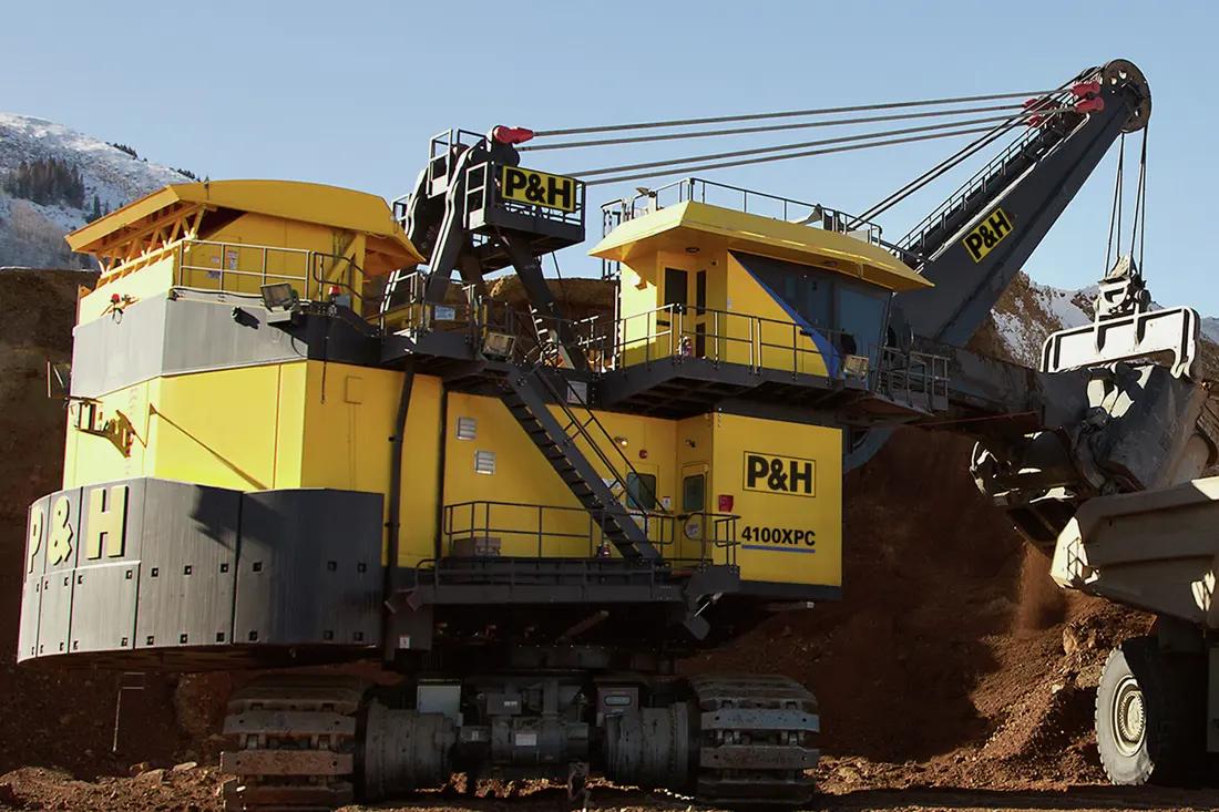
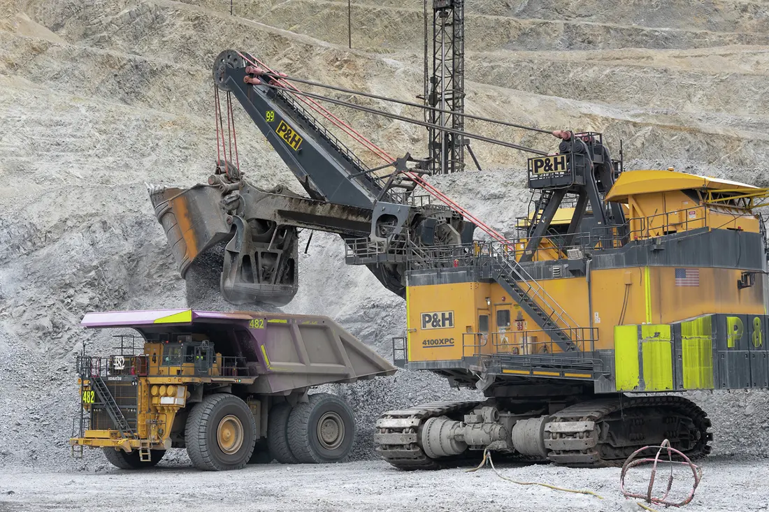
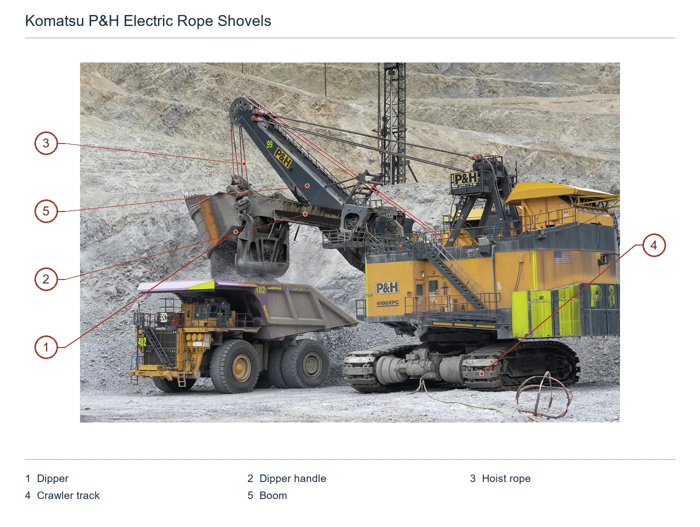
The numbers on the diagram correspond one to one with the rows below.

| No. | Component | Location | Applies to |
|---|---|---|---|
| 1 | Dipper | Shovel dipper at upper left | P&H 4100XPC OEM pictured configuration |
| 2 | Dipper handle | Dipper handle between bucket and machine | P&H 4100XPC OEM pictured configuration |
| 3 | Hoist rope | Hoist rope between boom tip and dipper | P&H 4100XPC OEM pictured configuration |
| 4 | Crawler track | Crawler undercarriage beneath shovel | P&H 4100XPC OEM pictured configuration |
| 5 | Boom | Main boom extending to upper left | P&H 4100XPC OEM pictured configuration |
Group parts by position and failure mode rather than assigning one material to all. Cards link to component pages and materials support initial selection. Final material, heat treatment and joining follow drawings, used parts and site wear.

Dipper Teeth & Adapters
At the dipper front, they take impact, compression and abrasion on penetration. Check shovel model, dipper size, tooth system, orientation, retention and used-part wear pattern.
View Dipper Teeth →
Dipper Lip & Shrouds
Protect the front and side wear zones and support the tooth system. Check lip profile, protector count, holes or locks, and adjacent adapters against dipper design.
View Lip Protectors →
Dipper Liners & Wear Plates
Cover floor, sides, back and high-flow erosion zones, replaced by wear map. Provide dipper model, plate location, thickness, holes, weld boundaries and used-part templates before manufacture.
View Dipper Liners →
Dipper Heel Wear Band
Located at the rear underside near the material. OEM TRC literature emphasizes a raised heel to reduce contact with ore. Restore existing structures according to their wear profile.
View Bottom / Heel Protectors →
Dipper Door & Roller Latch Wear Interfaces
Door, roller latch, pins and contacts face cyclic impact and opening/closing wear. Distinguish door structure, rollers, pins, bushings and hydraulic snubbers rather than grouping them as one generic part.
View Pins →
Crawler Shoes & Undercarriage Wear Parts
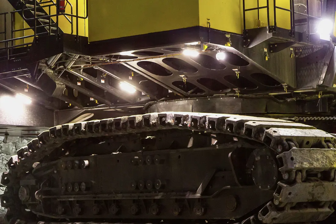
Heavy cast shoes carry machine weight, ground impact and ore wear, mating with drive sprockets and idlers. Check pitch, width, pin bores, grousers and side by model.
View Track Shoes →Check motors, gearboxes, gears, shafts, drums, ropes, bearings, bushings, brakes and seals separately for each motion system. This page describes identifiable assemblies and omits references by OEM catalogues or drawings.

Hoist Motors, Gearcase & Drum
Mining motors, enclosed gearing, brakes, drums and ropes lift the dipper. Drum diameter, gear stages and drive configuration vary by model; verify machine and assembly references.
View Heavy-Duty Drive Assemblies →
Crowd Drive, Rack & Pinion System
Crowd drives the twin-leg handle into the bank. Models may use belt-cushioned gearboxes or direct drive. Check handle racks, pinions, shafts, bearings, brakes and mounting centres.
View Gears and Pinions →
Swing Motors, Planetary Gearcases & Swing Gear
Multiple motors and modular planetary gearboxes rotate the upperworks through a one-piece forged swing gear. Check model, tooth count, module, pressure angle, tooth direction, mounting holes and housing interfaces.
View Gears and Pinions →
Propel Motors, Planetary Drives & Sprockets
Independent left/right drives deliver torque to sprockets, working with shoes and idlers. Check motor, brake, planetary gearbox, output shaft, sprocket profile, pitch and seals as a set.
View Heavy-Duty Drive Assemblies →
Shafts, Bearings, Bushings & Brakes
Each hoist, crowd, swing and propel system has dedicated shafts, rolling bearings, sliding bushings and brakes. Names alone do not establish interchangeability; provide system, model, assembly drawing and key fits.
View Bearings and Bushings →
Ropes, Sheaves & Rope Connections
Hoist and suspension ropes, boom-point sheaves, drum connections and rope-end anchors need frequent inspection. Verify model, rope diameter, construction, length, reeving, groove profile and safety standards.
View Heavy-Duty Drive Assemblies →No. The series narrows the scope; also provide full model, serial number, assembly, drawing or used part, dimensions and orientation. Do not assume interchangeability between 4100C, 4100XPC, AC-90 or different drive/dipper configurations.
Only traceable references are published. Confirmed drawing and model details are added at the relevant positions after obtaining OEM catalogues, installation drawings, reliable third-party drawings or site records.
No. It screens material families by impact, abrasion, fatigue, contact stress and fits. Final grade, hardness, heat treatment, inspection and tolerances require drawings, used-part analysis and site conditions.
Provide full model and serial number, mechanism, drawing/catalogue reference, photographs, dimensions, orientation, current material and ore conditions. ANRANST provides technical advice, supplier coordination, quality control and delivery.
Or contact us directly: +86 156 3797 3199
zzx@anranst.com
ANRANST provides customers worldwide with engineering assessment, production at certified foundries to the customer technical requirements, quality control and finished-part delivery for custom wear parts and industrial spares, with scope to support other custom industrial parts.
We review mating surfaces and interface dimensions and assess material, heat treatment and manufacturing feasibility.
Material grades and heat-treatment processes are specified order by order, stated in the technical agreement and tracked through production.
Drawing confirmation, material and process control, production tracking, inspection and acceptance coordination.
We coordinate manufacturing, quality confirmation, packaging and delivery of complete finished parts in a workable, closed-loop supply process.
Provide the existing model, drawings, drawing, materials or operating conditions so we can identify the appropriate technical review and supply route.
Submit an Enquiry