CITIC HIC CSM Vertical Stirred Mill

Start with CSM-1120 and the complete installed-equipment documentation, then identify the screw agitator, liners, feed and discharge parts, screens, bearings, seals, materials and inquiry requirements.

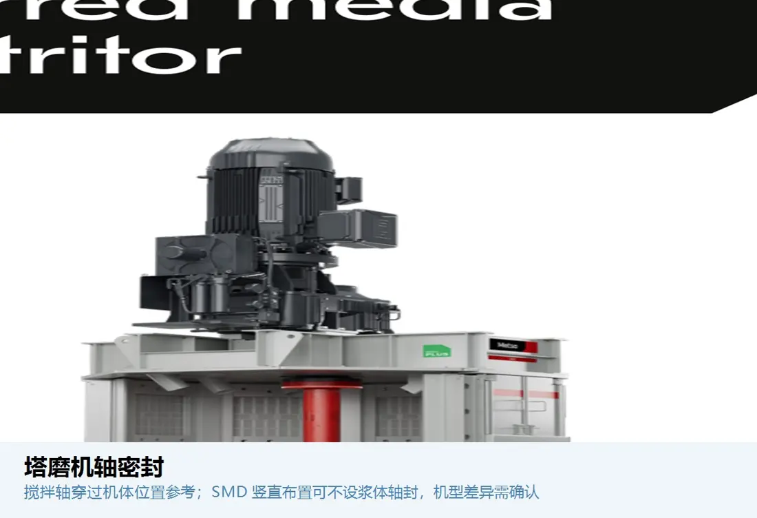
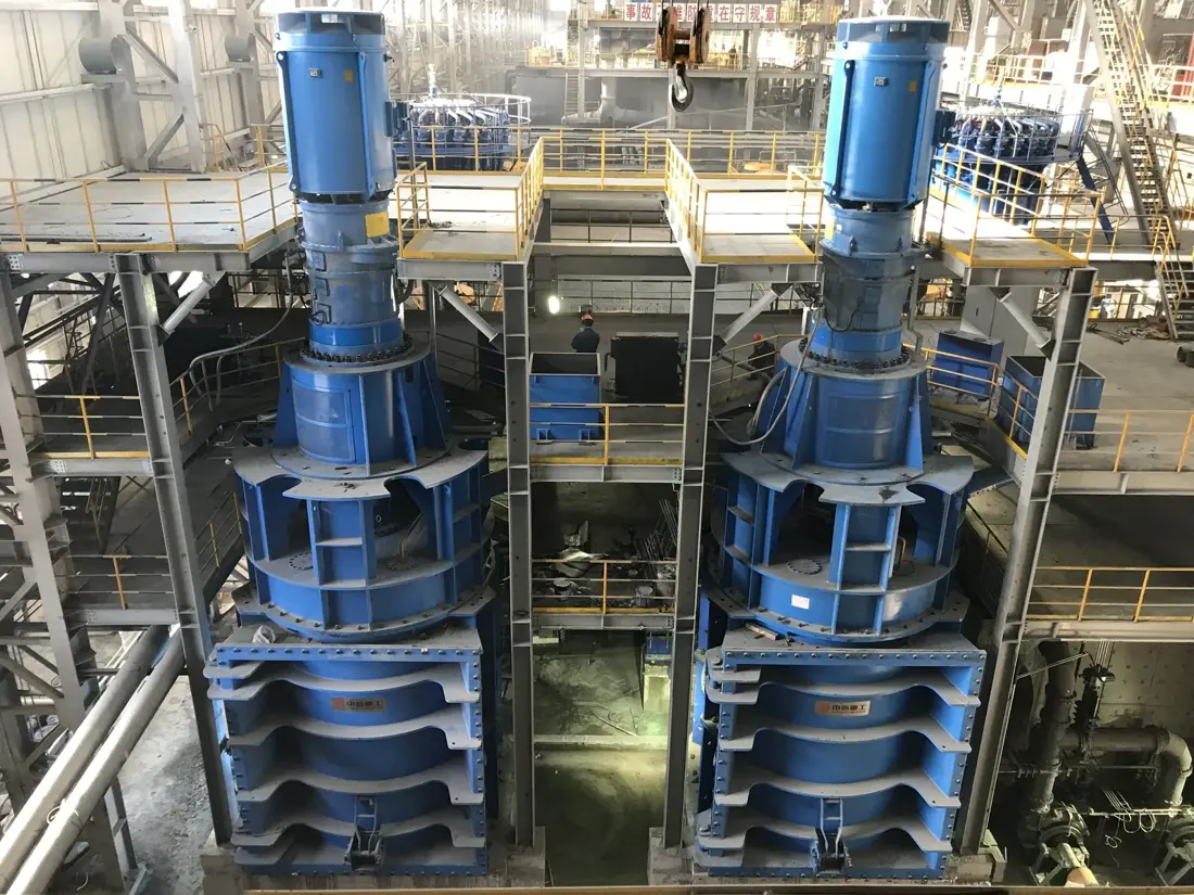
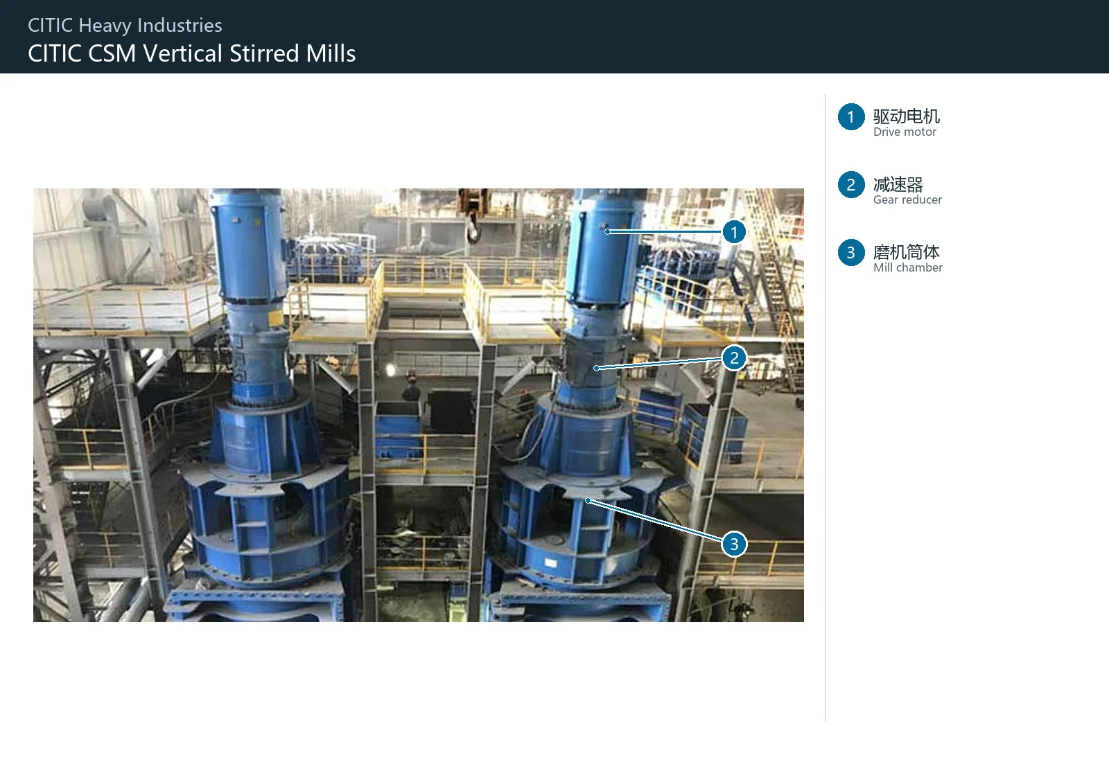
Official CITIC HIC CSM vertical stirred mill product image
Official CITIC HIC CSM vertical stirred mill product image. Confirm the installed machine from the complete model, project nameplate, grinding chamber, agitator, drive and equipment documentation.
OEM Equipment Details

Models, Wear Systems and Core Spares on One Page

This page uses the CSM-1120 listed in CITIC HIC's published project information to organize model identification and spare-part paths. Confirm other installed models and power ratings from project documentation.

CSM-1120 Published Model
8 Wear and Screening Parts
2 Bearings and Seals
1 Technical Enquiry
Standard Models and Key Dimensions

CSM Model and Core Identification Fields

CSM-1120 supports installed-equipment searches. Before manufacture, confirm the grinding chamber, agitator, shell, drive, shafting and drawing revision.

ModelModel StatusKey dimensionsRequired Checks Before Manufacturing
CSM-1120Listed in CITIC HIC published project informationGrinding chamber, agitator and shell dimensions confirmed by project drawingsProject, nameplate, general arrangement, drive, shafting, liners and drawing revision

CSM-1120 is the current model entry. Confirm other installed CSM mills separately from the nameplate, project documents and drawings.

Wear Parts

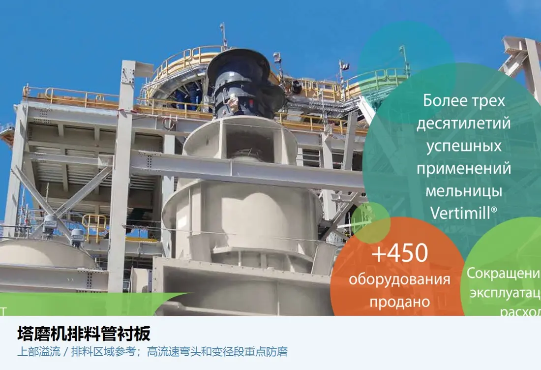
Agitator, Shell, Bottom, Feed, Discharge and Screening Wear Systems

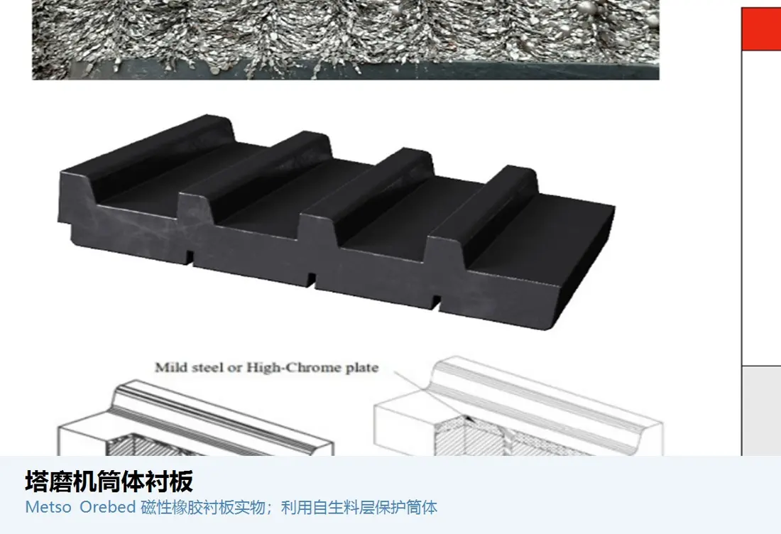
Each position is exposed to different high-velocity wear, slurry erosion, localized impact, corrosion or plugging risk, so materials and manufacturing processes are confirmed separately.

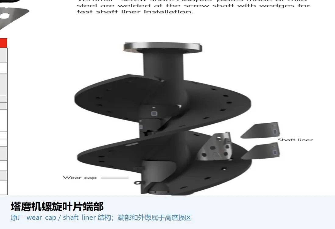
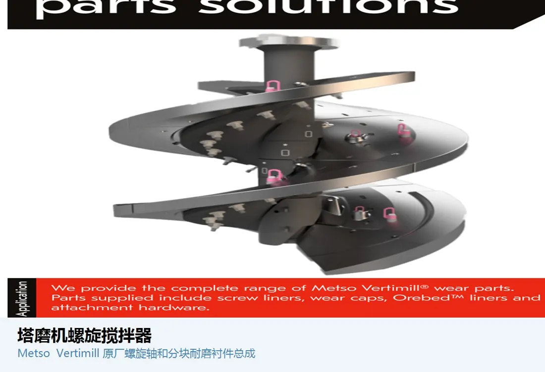
Screw-agitator identification image
01

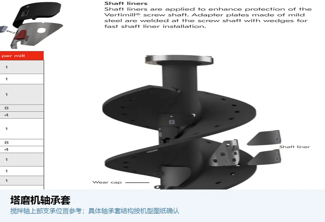
Screw Agitator

Screw / Impeller Agitator

Transfers energy within the grinding chamber and circulates grinding media and slurry. Confirm overall length, diameter, pitch, hand of rotation, shaft interface, segmented construction and installation direction.

Material Selection: Confirm wear-resistant alloy steel, high-chromium cast iron, ceramic or composite wear construction according to abrasive wear, impact, slurry corrosion and maintenance method.

View Part Details →
Screw-flight tip wear-part identification image
02

Screw-Flight Tip Wear Parts

Screw Tip / Flight Tip

Protects the outer edge and high-velocity tip area of the screw flight. Confirm position, left/right orientation or hand of rotation, curvature, thickness, hole pattern, segmentation and agitator interface.

Material Selection: Confirm high-chromium cast iron, wear-resistant alloy steel, cemented carbide or ceramic-composite construction according to localized wear, impact and replacement method.

View Part Details →
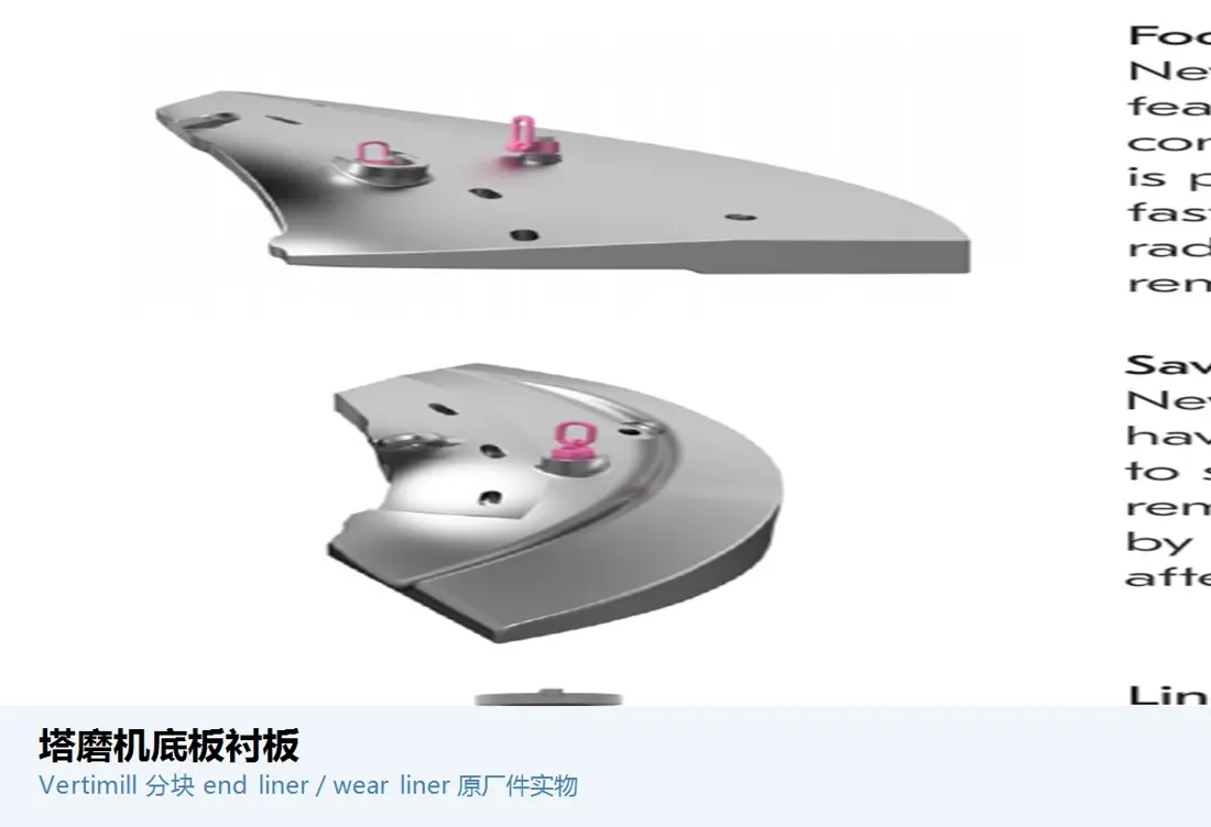
Bottom / base liner identification image
04

Bottom / Base Liner

Bottom Plate / Base Liner

Protects the bottom of the grinding chamber and the flow-turning zone. Confirm inside and outside diameters, segmentation, thickness, center opening, hole pattern, support surface and discharge interface.

Material Selection: Confirm high-chromium cast iron, wear-resistant alloy steel, ceramic or composite construction according to sedimentation, wear, impact and assembly method.

View Part Details →
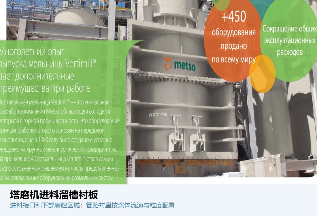
Discharge-pipe liner identification image
06

Discharge Pipe Liner

Discharge Pipe Liner

Protects discharge piping against slurry erosion and abrasive wear. Confirm inside and outside diameters, length, bend angle, flange, interfaces, flow direction and replaceable construction.

Material Selection: Confirm high-chromium cast iron, rubber, polyurethane, ceramic or composite pipe liners according to flow velocity, particle size, corrosion and pressure.

View Part Details →
Internal classification-screen identification image
07

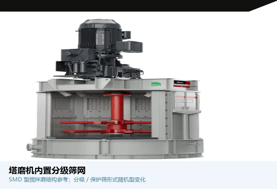
Internal Classification Screen

Internal Classifying Screen

Located at the internal classification or media-control position. Confirm location, apertures, slot width, outside diameter, thickness, support, orientation and adjacent channels.

Material Selection: Confirm wear-resistant stainless steel, alloy steel, polyurethane or composite screens according to particle size, wear, corrosion and plugging risk.

View Part Details →
Media-retention screen identification image
08

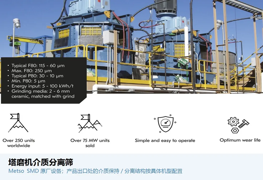
Media Separation Screen

Media Separation Screen

Prevents grinding media from entering the discharge system. Confirm slot width, open area, outside diameter, support, installation direction, media size and wear records.

Material Selection: Confirm wear-resistant stainless steel, alloy steel, polyurethane or composite screening construction according to media, wear, corrosion and plugging.

View Part Details →
Spare Parts

Bearing Bushes and Shaft-Seal Spares

Check bearings and seals separately against the complete model, shaft and housing diameters, fits, tolerances, loads, speed, lubrication, flushing, process medium and temperature.

Bearing-bush identification image
01

Bearing Bush

Bearing Sleeve

Supports the rotating shafting and maintains the specified clearance. Confirm shaft and housing diameters, inside and outside diameters, length, flange, oil grooves, fits, tolerances and lubrication.

Material Selection: Confirm bearing bronze or the original sliding-bearing material according to bearing pressure, speed, temperature rise, slurry isolation and lubrication.

View Part Details →
Shaft-seal identification image
02

Shaft Seal

Shaft Seal

Isolates slurry, dust and lubricant. Confirm shaft diameter, groove, face or lip construction, pressure, temperature, speed, process medium and flushing method.

Material Selection: Confirm NBR, HNBR, FKM, PTFE, polyurethane or mechanical-seal materials according to medium, pressure, temperature and speed.

View Part Details →
Drawing and Spare Part Numbers

CSM Drawing Number and Third-Party Part Number Check

CSM part numbers must be confirmed against the complete model, installation position and drawing revision. Numbers are not inferred on this page.

Selection Guidelines: Part numbers must match the model, project, installation position and installed-equipment drawings. OEM drawing numbers and third-party part numbers are checked separately.

Why does this page list only CSM-1120?

CITIC HIC's published project information lists CSM-1120. Confirm other installed models and power ratings from the complete nameplate, project and equipment documentation.

Can the agitator and screw-flight tip wear parts be replaced by shape alone?

No. Also confirm the complete model, overall length, diameter, pitch, hand of rotation, shaft interface, segmentation, operating clearance, material, process and drawing revision.

How can CSM parts be identified without a drawing number?

Submit the nameplate and project, photographs of the grinding chamber and agitator, general arrangement, installation position, used parts, wear records and key dimensions to assess identification, reverse engineering and manufacturing requirements.

Submit the CITIC HIC CSM model, project, drawing number, agitator or liner requirement

Provide the complete model, project, serial number, grinding-chamber and agitator dimensions, drawings, used-part photographs, materials, media and operating conditions. We will use them for identification, material assessment, manufacturing matching, quality control and finished-part delivery.

Manufacturing Services in China

From Technical Assessment to Finished-Part Delivery

ANRANST provides customers worldwide with coordinated consulting, supplier sourcing, quality control and finished-part delivery for custom parts, wear parts and industrial spares from China, with scope to support other custom industrial parts.

01

Technical Advice

Equipment and part identification, drawing review, material selection and manufacturing feasibility assessment.

02

Supplier Introductions

Match requirements with suitable manufacturers in China and coordinate the exchange of technical information.

03

Quality Control

Drawing confirmation, material and process control, production tracking, inspection and acceptance coordination.

04

Finished-Part Delivery

Coordinate manufacturing, quality confirmation, packaging and delivery of complete finished parts.

Provide the existing model, drawings, drawing or part numbers, materials or operating conditions so we can identify the appropriate technical review and supply route.

Submit an Enquiry