
01
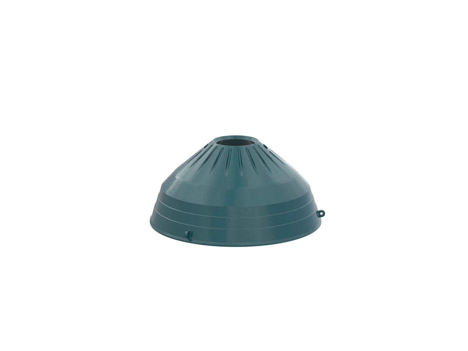
Mantle / Head Liner
Mantle / Head Liner
Mounted on the crushing head, the mantle withstands compression, impact and abrasion.Confirm chamber, contour, thickness and mating surfaces against installation drawings.
View the common part page →Model identification, wear parts, drive and structural spares, material checks and supply to drawing for legacy installations.
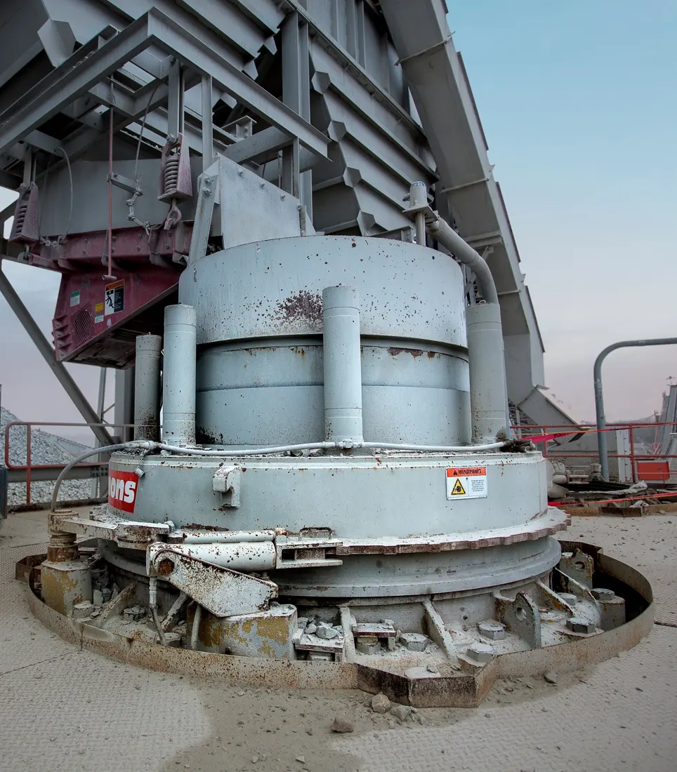
Metso states that it has held the original Symons cone crusher drawings and product specifications since 1928 and continues to support 2, 3, 4, 4¼, 5½ and 7 ft installations. Omnicone 937, 1144, 1352 and 1560 are also retained here for spare-part identification on older equipment.
Models provide a starting point for spare-part searches. Within one size, verify standard / short-head type, chamber, age, assembly configuration, serial number and drawing revision.
| Series | Standard model / size | Key quotation checks |
|---|---|---|
| Nordberg Symons | 2 ft | Complete size, standard / short-head type, chamber and serial number |
| Nordberg Symons | 3 ft | Complete size, standard / short-head type, chamber and serial number |
| Nordberg Symons | 4 ft | Complete size, standard / short-head type, chamber and serial number |
| Nordberg Symons | 4¼ ft | Complete size, standard / short-head type, chamber and serial number |
| Nordberg Symons | 5½ ft | Complete size, HD / SHD configuration, chamber and serial number |
| Nordberg Symons | 7 ft | Complete size, HD / XHD / SHD configuration, chamber and serial number |
| Nordberg Omnicone | 937 | Nameplate, serial number, general arrangement, drawing and installed-part dimensions |
| Nordberg Omnicone | 1144 | Nameplate, serial number, general arrangement, drawing and installed-part dimensions |
| Nordberg Omnicone | 1352 | Nameplate, serial number, general arrangement, drawing and installed-part dimensions |
| Nordberg Omnicone | 1560 | Nameplate, serial number, general arrangement, drawing and installed-part dimensions |
The numbers on the diagram correspond one to one with the rows below.
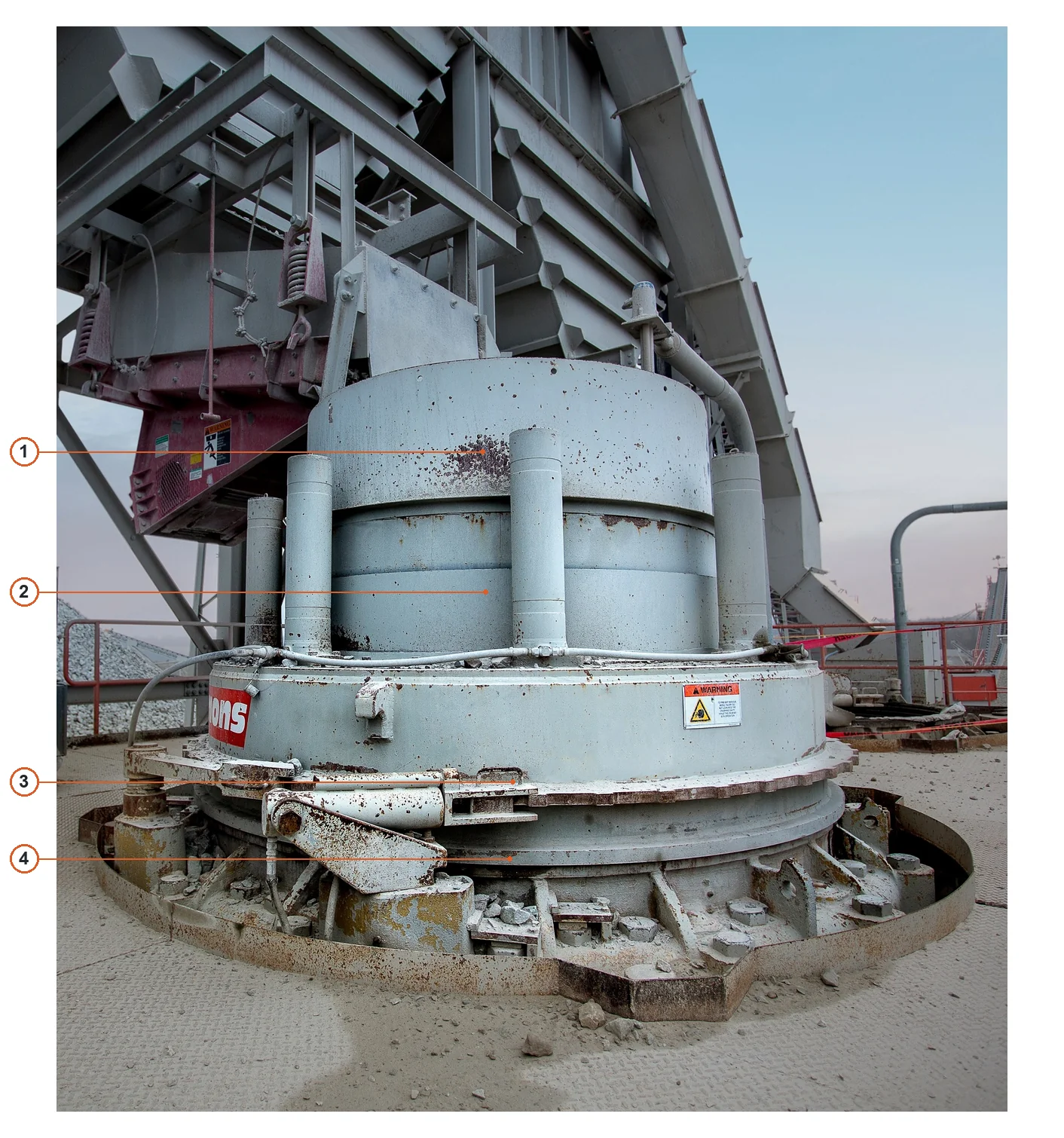
| No. | Component | Location | Applies to |
|---|---|---|---|
| 1 | Feed hopper | Upper cylindrical feed hopper | Symons photo configuration; exact specification not specified |
| 2 | Bowl | Bowl body below feed hopper | Symons photo configuration; exact specification not specified |
| 3 | Adjustment ring | Circumferential adjustment ring below bowl | Symons photo configuration; exact specification not specified |
| 4 | Main frame | Load-bearing frame below adjustment ring | Symons photo configuration; exact specification not specified |
The three core wear-part categories link to common part pages. Complete the technical check using the Symons or Omnicone model, chamber, profile, drawing and material.
Mantle / Head Liner
Mounted on the crushing head, the mantle withstands compression, impact and abrasion.Confirm chamber, contour, thickness and mating surfaces against installation drawings.
View the common part page →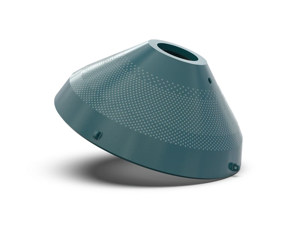
Bowl Liner / Concave
Mounted inside the bowl, it forms the chamber with the mantle.Material selection must consider feed size, ore abrasiveness, target product and chamber.
View the common part page →
Feed Plate / Feed Cone
Located at the feed entrance, it distributes material and withstands impact and local sliding wear. Confirm contour, holes and material against the original part drawing, feeding arrangement and wear condition. The image is generic.
View the common part page →Metso's manufacturer information lists Symons frames, bushings, shafts, gears and pinions, adjustment rings / bowls and heads. The entries below divide these further by function.
Main Frame & Structural Parts
Carry machine loads and establish system datums. Check casting revision, mounting interfaces, reference dimensions, cracked areas and inspection requirements.
Submit Drawings or a Nameplate →Adjustment Ring & Bowl
Control discharge adjustment, locking and concave mounting. Check threads, locking method, standard / short-head configuration and hydraulic upgrades.
Submit the Model and Drawing →Head & Main Shaft Assembly
Transmit crushing forces and produce eccentric oscillation. Check head revision, shaft dimensions, bushing fits, sealing and liner interfaces.
Submit the General Arrangement and Dimensions →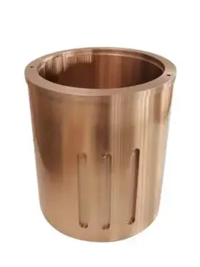
Bushings & Plain Bearings
Includes eccentric, head and countershaft bushings.Check inside and outside diameters, length, oil grooves, interference and copper-alloy system for each part.
View the common part page →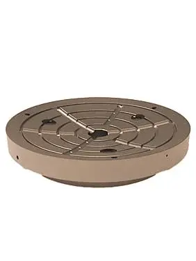
Socket Liner
Supports the head under oscillating contact loads. Check spherical radius, thickness, lubrication, contact condition and material. The image is generic.
View the common part page →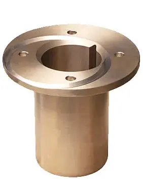
Pinion Shaft, Countershaft & Bushings
Transmit torque from the motor side to the eccentric. Check shaft diameter, bearing seats, splines or keyways, gear connection and bushing fits. The image is generic.
View the common part page →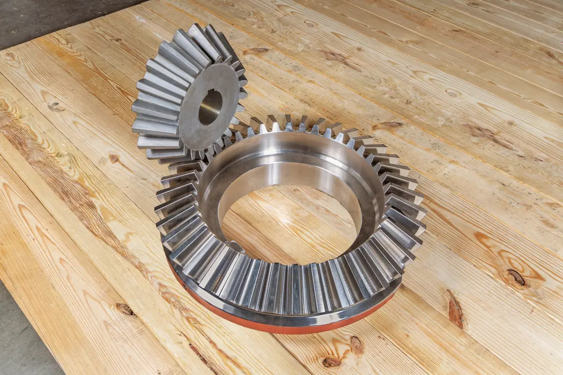
Gear & Pinion
Transmit drive power and change its direction. Check straight or spiral bevel teeth, tooth count, module, pressure angle, rotation direction, matched-pair markings and heat treatment. The image shows actual Symons spare parts.
View Gear Components →Eccentric Assembly & Thrust Parts
Generate eccentric head motion and carry axial loads. Check eccentricity, bushings, thrust plates, oil passages and gear interfaces. The image is generic.
View Thrust Components →Sealing, Lubrication & Hydraulic Parts
Protect sliding surfaces and maintain adjustment, locking and tramp release. Check water or grease sealing, hydraulic modification status, interfaces and medium. The image is generic.
View Seal Components →Upgrades change spare-part interfaces and quotation scope. The table helps identify modifications already installed; it is not an unchecked interchangeability commitment.
| Upgrade system | Metso's published application range | Additional quotation information |
|---|---|---|
| Advanced bowl adjustment | Symons 7 ft | Upgrade nameplate, hydraulic interfaces and control-system revision |
| Hydraulic motor adjustment system | 5½ ft HD; 7 ft HD / XHD / SHD | Adjustment ring, drive and locking configuration |
| Hydraulic tramp release and cavity clearing | 5½ ft HD; 7 ft HD / XHD / SHD | Hydraulic unit, cylinders, piping and control revision |
| Hydraulic lockposts | 5½ ft; 7 ft HD / XHD / SHD | Lockposts, hydraulic interfaces and bowl configuration |
| Hydraulic power unit | 5½ ft HD; 7 ft HD / XHD / SHD | HPU model, pressure, flow and interfaces |
| Packaged lubrication unit | 5½ ft HD; 7 ft HD / XHD / SHD | PLU model, pumps, cooling and filtration configuration |
| Symons HydroLoop | All Symons sizes | Water-seal circuit, mounting space and site interfaces |
Provide the brand, complete model, standard or short-head type, chamber, serial number, drawing, installation position, used-part photographs and key dimensions.
Foot size alone is insufficient. Standard or short-head type, chamber, age, assembly configuration and drawing revision can change interfaces and dimensions.
Submit the nameplate, general arrangement, installation position, used-part photographs and key dimensions first. These establish whether dimensional inspection, material assessment and manufacture to drawing are feasible.
Provide the complete model, standard or short-head type, chamber, serial number, nameplate, drawing, used-part photographs and key dimensions. We use these for identification, material assessment, manufacturing coordination, quality control and finished-part delivery.
Or contact us directly: +86 156 3797 3199
zzx@anranst.com
ANRANST provides customers worldwide with engineering assessment, production at certified foundries to the customer technical requirements, quality control and finished-part delivery for custom wear parts and industrial spares, with scope to support other custom industrial parts.
We review mating surfaces and interface dimensions and assess material, heat treatment and manufacturing feasibility.
Material grades and heat-treatment processes are specified order by order, stated in the technical agreement and tracked through production.
Drawing confirmation, material and process control, production tracking, inspection and acceptance coordination.
We coordinate manufacturing, quality confirmation, packaging and delivery of complete finished parts in a workable, closed-loop supply process.
Provide the equipment brand, complete model and serial number, part name, part number or drawing number, drawing revision, quantity, material requirements and duty. If identifiers are unavailable, send photographs and key dimensions.
Submit an Enquiry