Metso Nordberg HP Series Cone Crushers

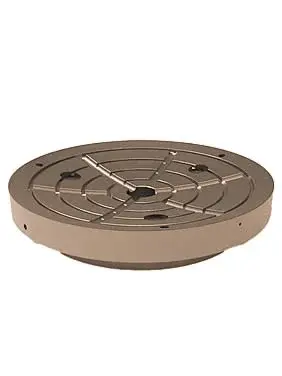
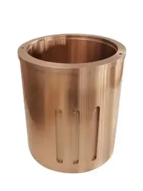
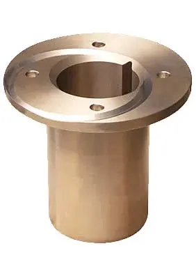
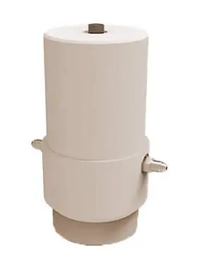
Identification and supply support for mantles, concaves, feed cones, bushings, hydraulic components, drive parts and dedicated tooling for HP100–HP900 and HP3–HP6 installations.

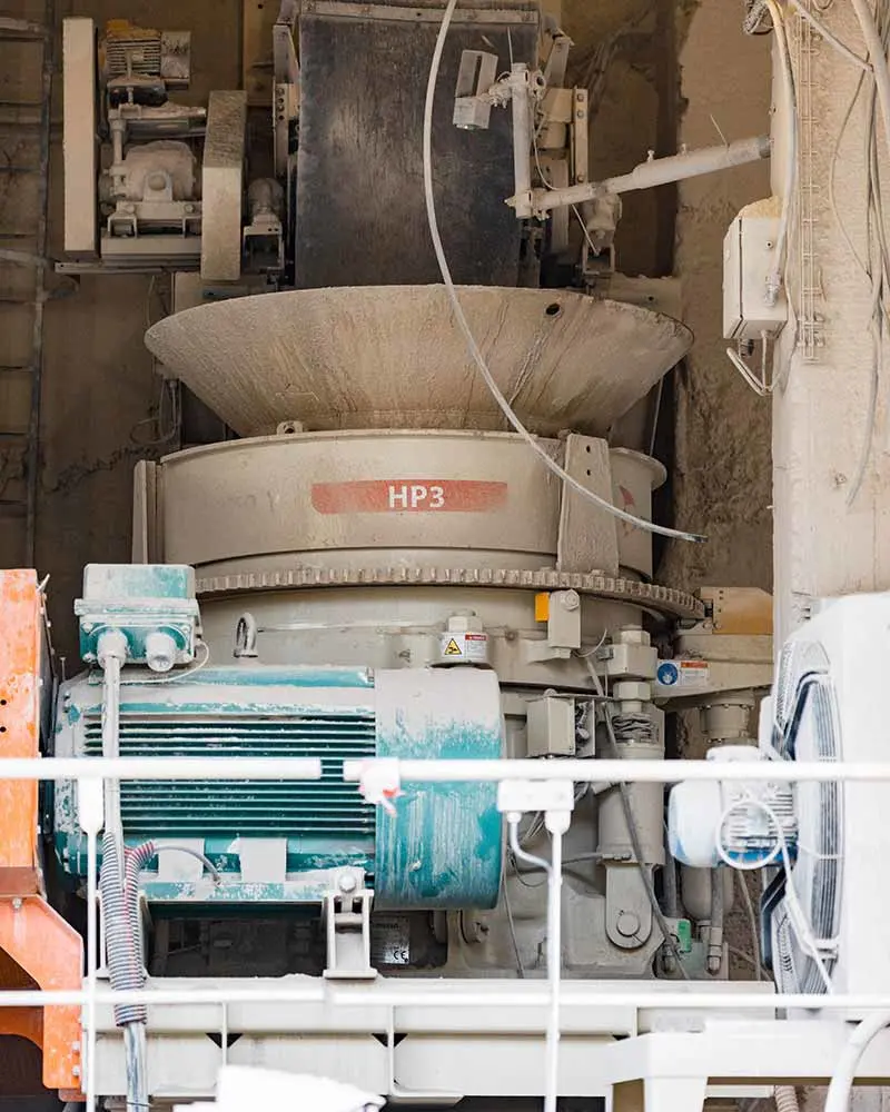
Metso Nordberg HP3 cone crusher at site
Nordberg HP3 equipment at site, used to confirm the feed, drive and adjustment-system configuration.
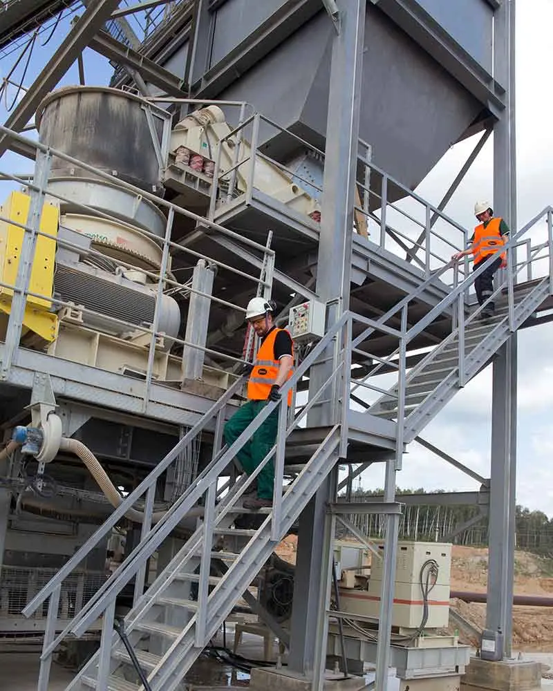
Installed Metso Nordberg HP Series cone crusher
HP Series installation used to check the frame, hydraulic system and peripheral interfaces.
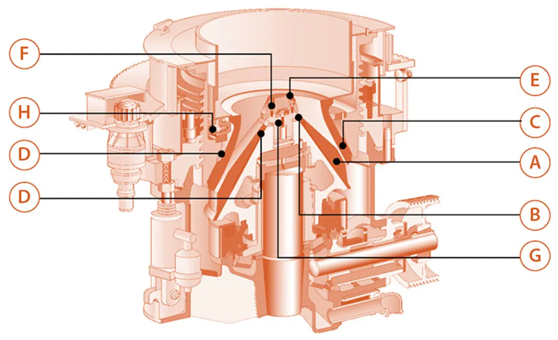
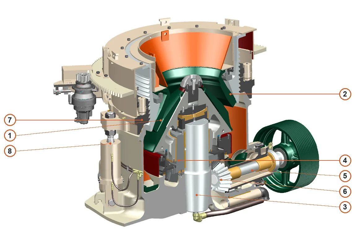
Cutaway view and wear-part locations in a Nordberg HP Series cone crusher
HP Series cutaway structure showing the mantle, concave, feed cone, bushings, shafting and hydraulic areas.
OEM Equipment Series

Start spare-part confirmation with the complete model, crushing cavity and liner combination

The same HP Series model may use standard, short-head and several cavity configurations. Mantles and concaves must be checked as a matched set. Bushings, hydraulic components and drive parts also require confirmation against the serial number, interfaces and drawing revision.

10OEM-Published Models
735–1780 mmHead Diameter
150–356 mmMaximum Feed Opening
90–700 kWInstalled Power
OEM-Published Specifications (2023)

Nordberg HP Series Model Range

The table retains the head diameter, maximum feed opening, installed power and maximum capacity published in the OEM manual for preliminary identification of installed equipment and spare parts.

Standard ModelsHead DiameterMaximum Feed OpeningInstalled PowerMaximum capacity
HP100735 mm150 mm90 kW155 t/h
HP200940 mm185 mm132 kW250 t/h
HP3001120 mm241 mm220 kW440 t/h
HP4001320 mm304 mm315 kW630 t/h
HP5001520 mm351 mm355 kW790 t/h
HP9001780 mm356 mm700 kW2000 t/h
HP31000 mm220 mm250 kW388 t/h
HP41120 mm252 mm315 kW555 t/h
HP51250 mm317 mm370 kW600 t/h
HP61400 mm331 mm500 kW790 t/h
Feed opening and capacity vary with the cavity, setting, material and operating conditions. Manufacturing liners or spare parts still requires confirmation of the standard or short-head configuration, cavity, drawing and installed version.
Metso

Component Location Diagram

The numbers on the diagram correspond one to one with the rows below.

Metso Nordberg HP Series Cone Crushers – Component Location Diagram
No.ComponentLocationApplies to
1MantleGreen mantle on moving headNordberg HP Series
2Bowl linerStationary bowl liner facing mantleNordberg HP Series
3Main shaftLower central main shaftNordberg HP Series
4EccentricEccentric around main shaftNordberg HP Series
5CountershaftHorizontal countershaft on rightNordberg HP Series
6PinionPinion at inner end of countershaftNordberg HP Series
7Adjustment ringAdjustment ring around upper frameNordberg HP Series
8Hold-down cylinderVertical hold-down cylinder on leftNordberg HP Series
Wear Parts

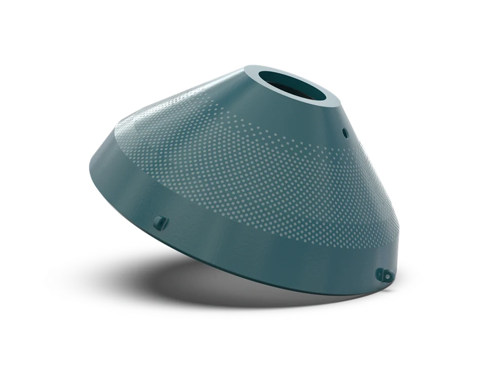
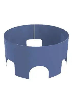
Crushing-Chamber Liners and Frame Guards

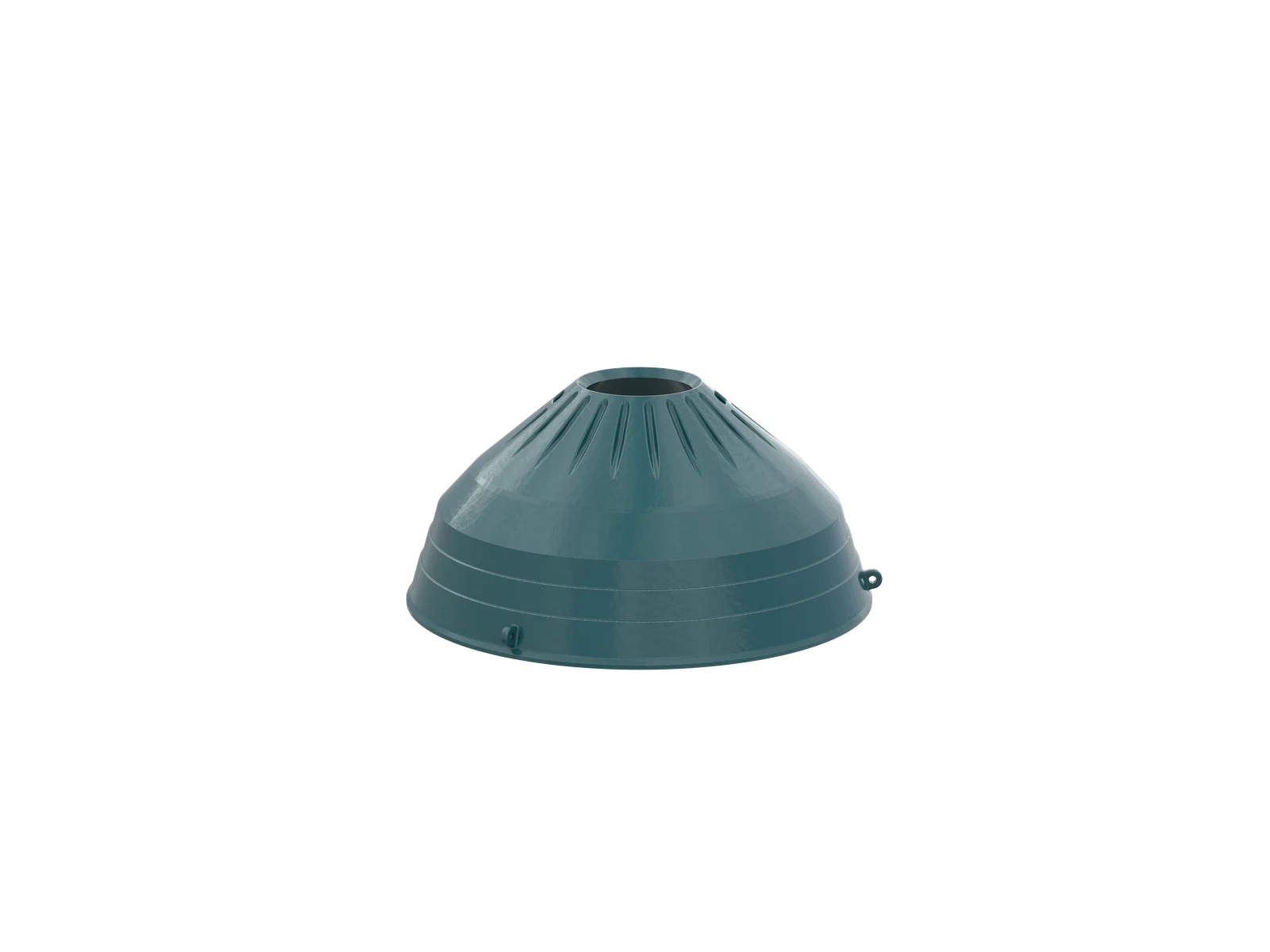
Each part is described by wear location, operating conditions and candidate material. The mantle and concave must be checked as a matched set for the selected cavity.

Spare Parts

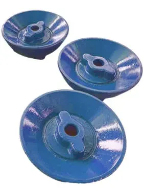
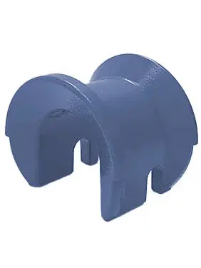
Bushings, Drive, Hydraulic and Locking Systems

General spare parts must be checked by fit, accuracy, material, lubrication, hydraulic interfaces and serial number; the HP model name alone is insufficient.

FAQ

Frequently asked questions

What information is needed to request a quote for HP Series mantle and concave liners?

Please provide the complete HP model, standard or short-head configuration, cavity profile, drawing or current model details, serial number, closed-side setting, photos of used parts, material and operating conditions.

Are liners for the same HP model directly interchangeable?

No. The same model may use standard, short-head and several cavity configurations. The mantle and concave must be checked as a matched set, together with the drawing revision and fastening arrangement.

What materials are used for HP Series liners?

High-manganese steel is the conventional route. Composite or embedded wear solutions can also be evaluated for specific conditions. Selection depends on rock type, abrasiveness, feed, closed-side setting and wear pattern.

Submit the Nordberg HP Series model, drawing or spare-parts drawing

Provide the complete model, serial number, nameplate, installation position, photographs of the current part, drawings, material and operating conditions. We use these to identify the part, assess materials, organize production at certified foundries, coordinate quality control and arrange finished-part delivery.

Equipment Brand and ModelDrawingDrawing or DimensionsCurrent MaterialPhotographs of Failed PartsTarget Service LifeOperating Conditions
Request a Quote

Or contact us directly: +86 156 3797 3199
zzx@anranst.com

Manufacturing Services in China

From Technical Assessment to Finished-Part Delivery

ANRANST provides customers worldwide with engineering assessment, production at certified foundries to the customer technical requirements, quality control and finished-part delivery for custom wear parts and industrial spares, with scope to support other custom industrial parts.

01

Drawing and Engineering Review

We review mating surfaces and interface dimensions and assess material, heat treatment and manufacturing feasibility.

02

Material and Heat-Treatment Specification

Material grades and heat-treatment processes are specified order by order, stated in the technical agreement and tracked through production.

03

Quality Control

Drawing confirmation, material and process control, production tracking, inspection and acceptance coordination.

04

Finished-Part Delivery

We coordinate manufacturing, quality confirmation, packaging and delivery of complete finished parts in a workable, closed-loop supply process.

Provide the equipment brand, complete model and serial number, part name, part number or drawing number, drawing revision, quantity, material requirements and duty. If identifiers are unavailable, send photographs and key dimensions.

Submit an Enquiry