McLanahan Apron Feeders

Review project configuration, throughput, chain sizes, pan widths, wear liners, head/tail shafts and drive spares together.

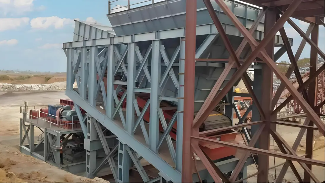
Official McLanahan Apron Feeder mining installation photograph
Official McLanahan Apron Feeder installation photograph showing feed beneath the hopper, pan-and-chain body, supporting undercarriage and discharge end.
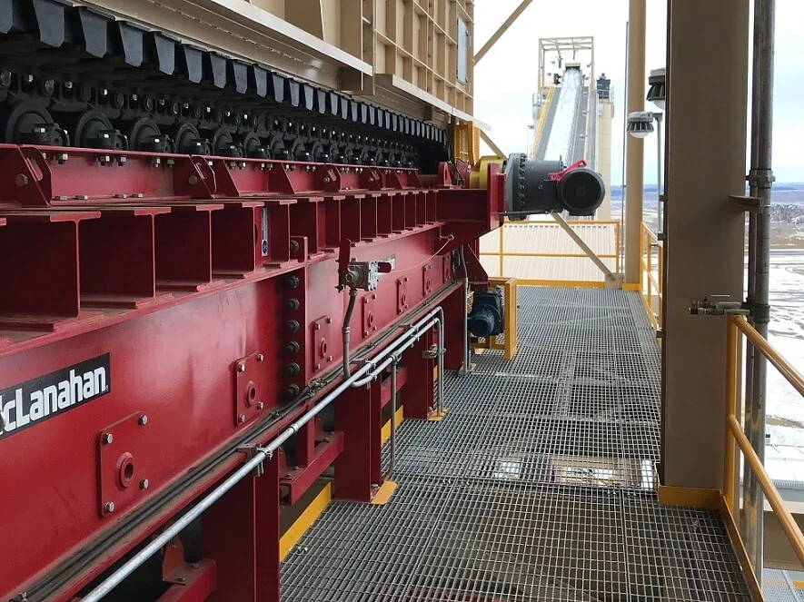
Official McLanahan Apron Feeder site side view
Official McLanahan site side view. Verify pans, chains, support rollers, frame and tail area against the specific project.
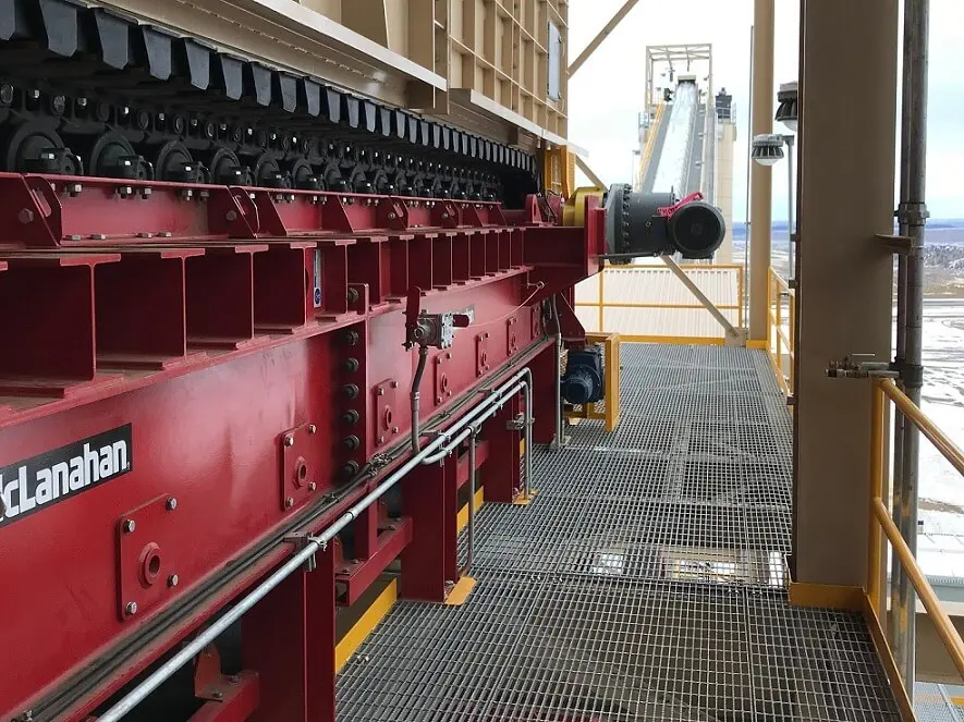
Official McLanahan Apron Feeder pan, chain and drive close-up
Official McLanahan close-up. Pan overlaps, chain undercarriage, drive end and supports are key spare-identification areas.
OEM equipment guide

Engineered Configurations, Pan Chains and Undercarriage Spares on One Page

Current McLanahan Apron Feeders are engineered for duty and project requirements; no fixed model table covers every installation. This page presents published capacities, pan configurations, undercarriage maintenance identifiers and part-identification criteria. Before manufacture, verify project number, nameplate, general arrangement, drawing reference and used parts.

10–6,000 tph Published Capacity Range
6 Published Chain Size Count
16 Standard Pan Width Count
Project-Specific Centres, Inclination and Drive
Models and key specifications

Current McLanahan Apron Feeder Configurations and Key Dimensions

Current products combine capacity, chain size, pan width and project length. FL / FD labels identify undercarriage maintenance groups and must not be treated as complete machine models.

Configuration / Maintenance IdentifierPublished Design ScopePublished Capacity or DimensionsKey Spare-Part Checks
Engineered Apron Feeder6 chain sizes and 16 standard pan widths; length is project-specific10–6,000 tphFirst verify project number, pan width, centres, chain size, inclination, speed and drive.
Cast Manganese-Steel Pan ConfigurationHeavy-duty one-piece cast flight / pan for high-impact feed areasWidth and length selected for the projectCheck individual weight, overlaps, bolt holes, chain interfaces, left/right orientation and wear allowance.
Formed Steel Pan ConfigurationFabricated formed-steel flight / pan; welded or formed designWidth and length selected for the projectCheck thickness, forming radii, reinforcement, welds, hole patterns and overlap clearances.
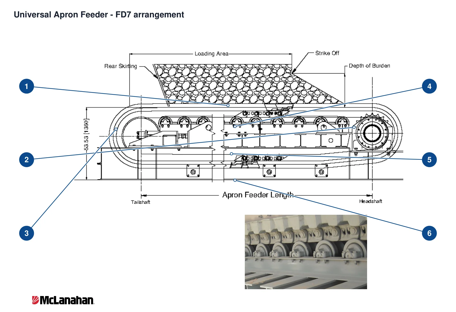
FL4 / FD4 / FD7 undercarriage identifiersSupport and return-roller maintenance group, not a fixed machine modelReturn-roller diameter 130 mm indicates approximately 50% wear; 120 mm approximately 100% wearCheck original roller diameter, shaft ends, bearings, seals, mounts and exact position.
FD9 / FD10 undercarriage identifiersLarge support and return-roller maintenance group, not a fixed machine modelReturn-roller diameter 219 mm indicates approximately 50% wear; 209 mm approximately 100% wearVerify project drawings, shaft-end dimensions, bearings and seals; series labels alone do not establish interchangeability.

Within the same capacity range, pans, chains, sprockets, rollers, centres, inclination, speed, drive and hopper interfaces can differ completely. The name “Apron Feeder” alone is insufficient for manufacture.

Wear parts

Pans, Hoppers, Skirts and Head/Tail Wear Parts

Distinguish drop impact, sliding erosion, trapped material and return spillage by installation position. Material pages support preliminary selection; project drawings and acceptance requirements determine final materials, processes and dimensions.

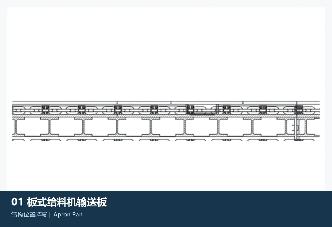
Generic apron feeder conveying and carrying pans
01

Conveying Pans / Carrying Plates

Flight / Pan

Take direct drop impact and are pulled by chains on both sides. The image shows a generic category, not a McLanahan OEM part. Verify cast manganese or formed-steel design, width, overlaps, holes, chain pitch and orientation.

Material review: McLanahan offers cast manganese-steel and formed-steel flights / pans. Project drawings determine the steel grade, heat treatment, thickness, welding and acceptance requirements.

View the Component Page →
Generic apron feeder hopper, side and skirt liners
02

Hopper, Side and Skirt Liners

Hopper, Side & Skirt Liner

Protect lump-impact areas, hopper sides and sealing skirts. The image identifies a generic category, not McLanahan OEM parts. Verify segmentation, thickness, holes, overlaps and left/right positions against assembly drawings.

Material review: Prioritise toughness and support in high-impact drop zones, and wear resistance in long sliding zones. Hardness alone is insufficient for material selection.

View the Component Page →
Generic apron feeder impact plates and wear-resistant supports
03

Impact Plates and Support Wear Strips

Impact Plate & Wear Rail

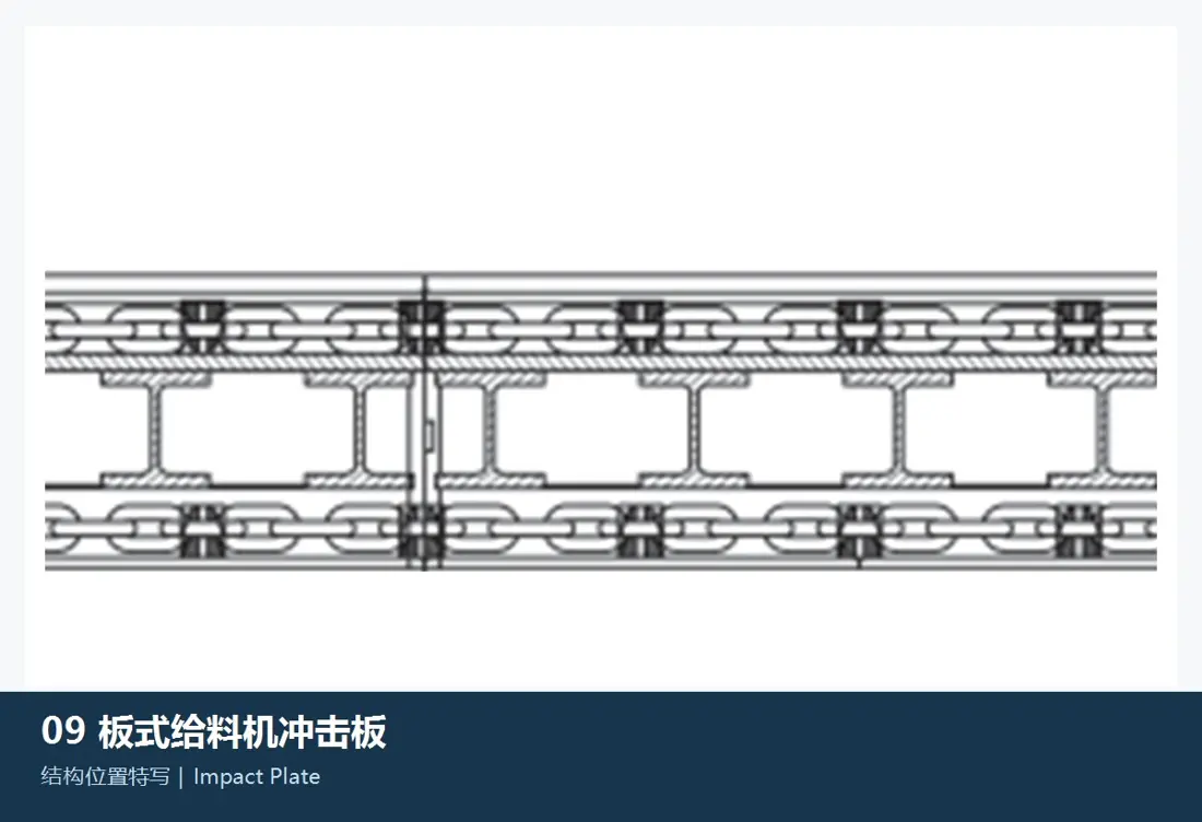
Located at high-drop feed points or beneath pans in local impact zones, protecting the frame and controlling pan-chain deflection. The image shows a generic category, not McLanahan OEM parts; position, thickness and fastening vary by project.

Material review: Select tough steel plate, quenched and tempered wear plate or composites by lump size, drop height, contact pressure and support stiffness. Confirm the grade after drawing review.

View the Component Page →
Generic apron feeder head discharge chute liner
04

Head Discharge Chute Liners

Head / Discharge Chute Liner

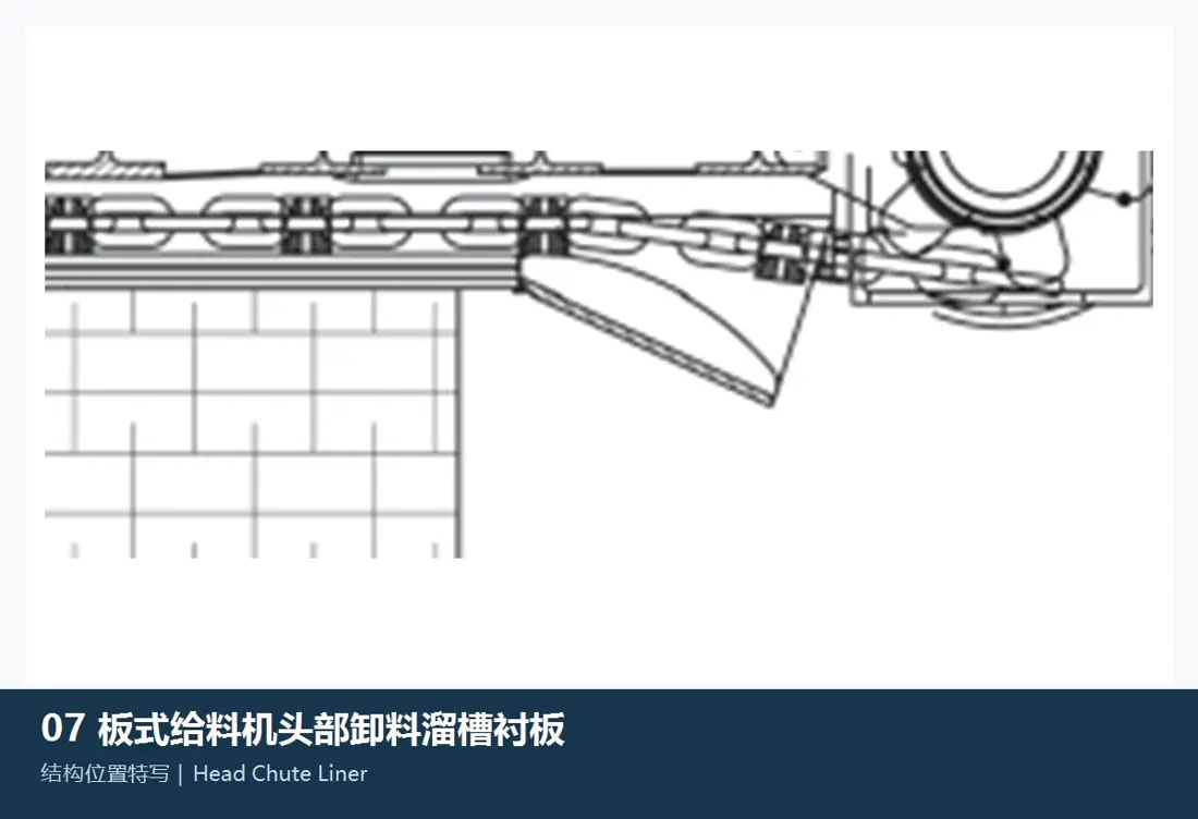
At the head wheel and discharge transfer, these face accelerating-flow erosion, turning impact and uneven wear. The image is generic, not McLanahan OEM. Check position, flow direction, curvature, holes and adjacent clearances.

Material review: Select materials by the impact-to-sliding-wear balance. Design high-impact and high-hardness areas separately rather than applying one liner solution everywhere.

View the Component Page →
Generic apron feeder tail feed-area liner
05

Tail Feed-Area Liners

Tail / Inlet Liner

Near tail feeding and chain return areas, these protect the frame and limit build-up effects on chains, tail wheels and tensioning. The image identifies a generic category, not McLanahan OEM parts.

Material review: Determine segmentation and materials by drop impact, trapping risk, pan-chain clearances and maintainability. Project drawings must supply dimensions and bolt layouts.

View the Component Page →
Generic apron feeder return-tray and dribble-pan liners
06

Return Tray / Dribble Pan Liners

Dribble / Drip Pan Liner

Used only where a return tray or dribble pan is installed, collecting spillage below the return chain and protecting the base. The image is generic, not McLanahan OEM; no part is specified where this structure is absent.

Material review: Prioritise thin-plate wear resistance, resistance to deformation, easy cleaning and replacement. Confirm material and thickness against actual build-up and erosion.

View the Component Page →
Spare parts

Pan Chains, Pins and Bushings, Sprockets, Head Shafts, Rollers and Drives

Chain pitch, pan width, centres, head/tail shaft interfaces, rollers and drive type form one system. Every replacement must match the installed machine and project number.

Generic apron feeder heavy-duty chain links
01

Heavy-Duty Chains, Pins and Bushings

Heavy-Duty Chain, Pin & Bushing

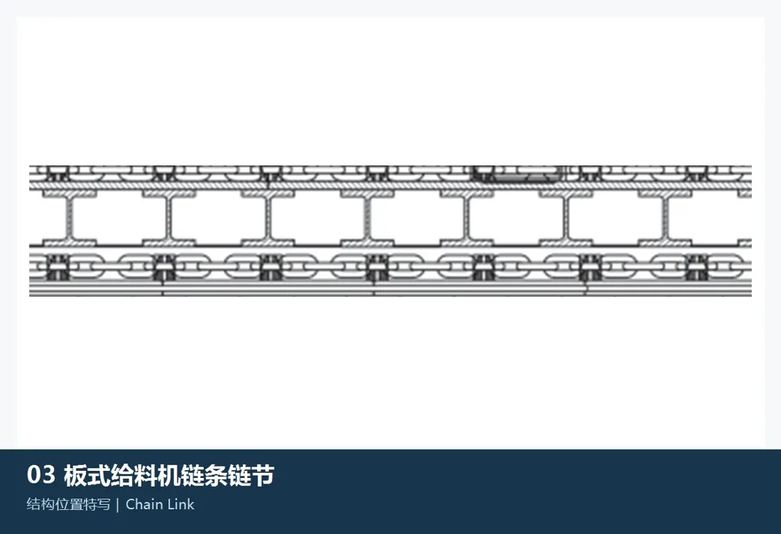
Side chains carry traction and maintain pan spacing. The image is generic, not McLanahan OEM. Check chain size, pitch, plates, pins, bushings, connecting links, left/right pairing and total links as a set.

Material review: Check chain plates, pins and bushings individually for strength, fatigue, core toughness, case depth, wear pairing and dimensional accuracy.

View the Component Page →
Generic apron feeder chain pins and bushings
02

Chain Pin and Bushing Pairs

Chain Pin & Bushing Pair

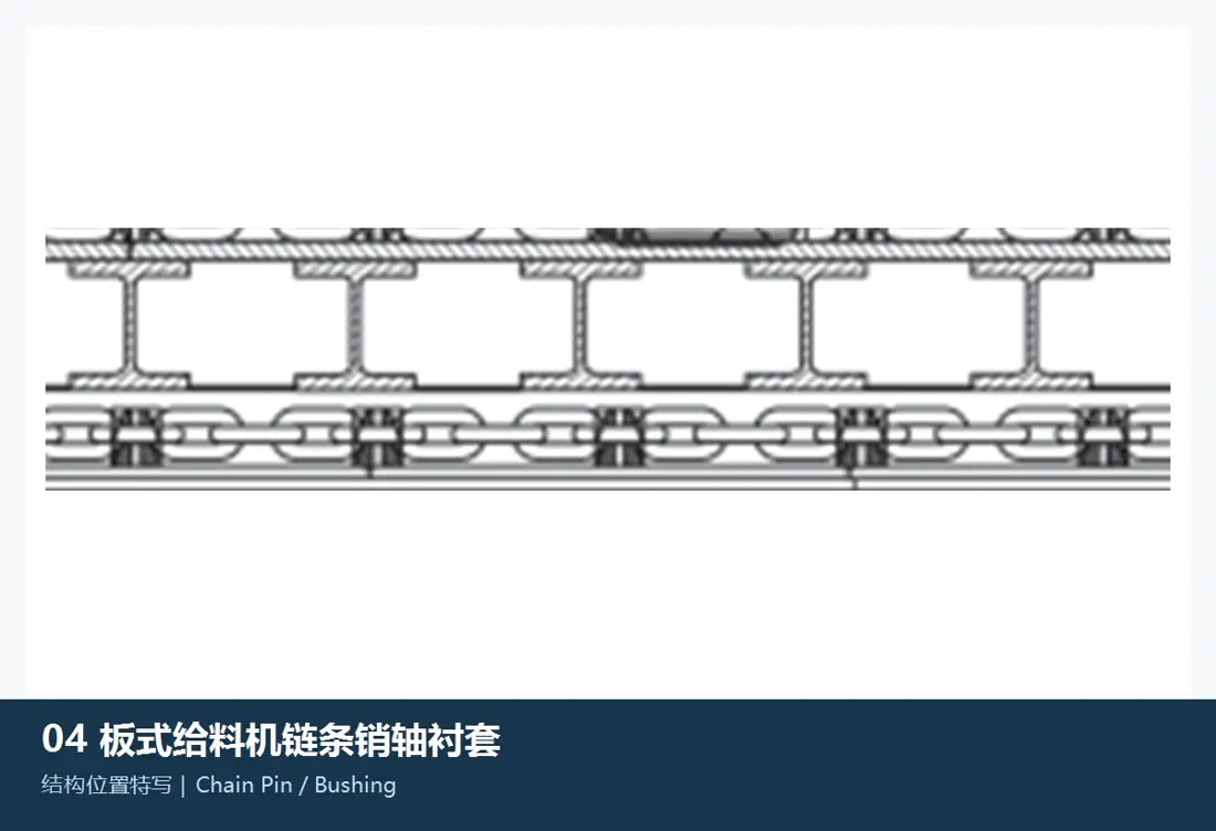
Pins and bushings determine articulation, elongation and chain life. The image is generic, not McLanahan OEM. Check outside/inside diameters, working length, lubrication, interference, hardened layer and chain-plate interfaces.

Material review: Material, carburising or induction hardening and core toughness must be matched. Surface hardness alone is insufficient to replace the original design.

View the Component Page →
Generic apron feeder split drive sprockets and hubs
03

Split Drive Sprockets, Hubs and Head Shafts

Segmental Sprocket, Hub & Head Shaft

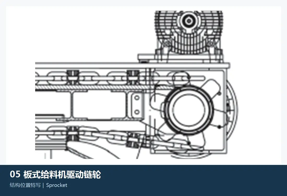
Published McLanahan designs can use split cast manganese-steel sprockets bolted to keyed hubs on heavy-duty head shafts. The image is generic, not OEM. Check teeth, chain pitch, pitch circle, segments, holes, keyways and shaft ends.

Material review: Verify sprocket teeth, hubs and head shafts individually for impact wear, torque, fatigue, fits and non-destructive testing.

View the Component Page →
Generic apron feeder carrying and return rollers
04

Carrying Rollers, Return Rollers and Tail Wheels

Carry Roller, Return Roller & Tail Idler

Support the pan chain and guide its path, forming key undercarriage maintenance items. The image is generic, not McLanahan OEM. Distinguish carrying rollers, return rollers and tail wheels; check diameters, shaft ends, bearings, seals and mounts.

Material review: Select roller and shaft alloy steels and surface treatment by contact stress, impact, fatigue and wear. Check bearings and seals against dust, temperature and lubrication.

View the Component Page →
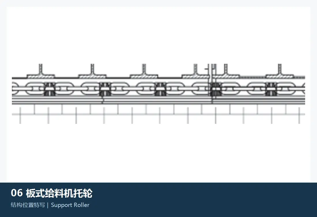
Generic apron feeder tail tensioning assembly
05

Tail Tensioning and Adjustment Parts

Tail Tensioning Assembly

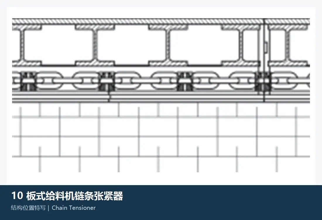
Maintain initial tension, side-to-side synchronisation and chain alignment. The image is generic, not McLanahan OEM. Check mechanical/hydraulic design, travel, screw or cylinder dimensions, mounting holes, handed parts and tail-shaft interfaces.

Material review: Check screws, rods, pins, slides and hydraulic parts individually for loads, thread accuracy, fatigue, corrosion protection, sealing and travel.

View the Component Page →
Drive and head assembly in the official McLanahan Apron Feeder side view
06

Geared Motor or Hydraulic Drive

Electromechanical or Hydraulic Drive

Current published McLanahan configurations support geared motor or hydraulic drives. Verify power, speed, torque, ratio, rotation, orientation, couplings, brakes and head-shaft interfaces for the project.

Material review: Check gears, shafts, couplings, housings, hydraulic motors and seals individually against nameplates, drawings, loads, lubrication and environmental conditions.

View the Component Page →

Can McLanahan Apron Feeder spares be identified by capacity alone?

No. Equal capacities can use different pan widths, centres, chains, pans, inclinations, speeds, rollers and drives. At minimum, provide the project number, nameplate, general arrangement, drawing reference or used-part dimensions.

Are FL4, FD4, FD7, FD9 and FD10 complete machine models?

This page uses them only as undercarriage and return-roller maintenance identifiers from McLanahan support literature, not as unsupported complete machine models.

Can pans and liners all use one material?

No. Pans, impact zones, sliding-flow areas and return-spillage areas have different loads and failure modes. Verify each against original drawings, material, lump size, drop height, speed and support conditions.

Send the Apron Feeder Project Number, Pan Width, Chain and Used-Part Details

Provide the complete nameplate, serial or project number, capacity, material and lump size, pan width, centres, inclination, speed, chain size, pan and roller photographs, drive nameplate, drawing reference and used-part dimensions. These support identification, material assessment, manufacturing coordination, quality control and finished-part delivery.

Manufacturing Services in China

From Technical Assessment to Finished-Part Delivery

ANRANST helps customers worldwide source custom parts, wear parts and industrial spares from China, coordinating technical advice, suppliers, quality control and finished-part delivery. The service can also extend to other custom industrial components.

01

Drawing and Engineering Review

Equipment and part identification, drawing checks, material selection and manufacturing feasibility assessment.

02

Material and Heat-Treatment Specification

Material grades and heat-treatment processes are specified order by order, confirmed in the technical agreement and tracked through production.

03

Quality Control

Drawing confirmation, material and process control, production monitoring, inspection and acceptance coordination.

04

Finished-Part Delivery

Coordinate manufacturing, quality confirmation, packaging and delivery of finished parts through a practical supply process.

Send the model, drawings, drawing or part numbers, material and operating conditions so we can define the technical checks and supply route.

Send Your Requirements